1. FUNCTIONS AND CONFIGURATION
1 - 4
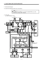
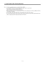
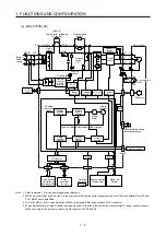
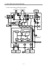
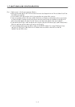
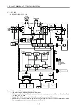
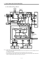
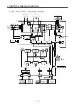
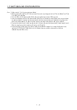
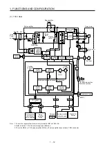
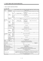
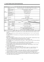
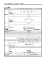
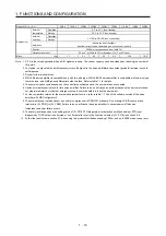
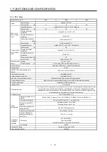
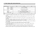
Note 1. The built-in regenerative resistor is not provided for MR-J4-10B(-RJ).
2. For 1-phase 200 V AC to 240 V AC, connect the power supply to L1 and L3. Leave L2 open.
Refer to section 1.3 for the power supply specifications.
3. Servo amplifiers MR-J4-70B(-RJ) or more have a cooling fan.
4. MR-J4 servo amplifier has P3 and P4 in the upstream of the inrush current suppression circuit. They are different from P1 and
P2 of MR-J3 servo amplifiers.
5. This is for MR-J4-_B-RJ servo amplifier. MR-J4-_B servo amplifier does not have CN2L connector.
6. The power factor improving AC reactor can also be used. In this case, the power factor improving DC reactor cannot be used.
When not using the power factor improving DC reactor, short P3 and P4.
Summary of Contents for MR-J4-100B(-RJ)
Page 17: ...8 MEMO ...
Page 143: ...4 STARTUP 4 20 MEMO ...
Page 199: ...5 PARAMETERS 5 56 MEMO ...
Page 227: ...6 NORMAL GAIN ADJUSTMENT 6 28 MEMO ...
Page 281: ...8 TROUBLESHOOTING 8 16 MEMO ...
Page 303: ...9 DIMENSIONS 9 22 MEMO ...
Page 319: ...10 CHARACTERISTICS 10 16 MEMO ...
Page 429: ...11 OPTIONS AND PERIPHERAL EQUIPMENT 11 110 MEMO ...
Page 435: ...12 ABSOLUTE POSITION DETECTION SYSTEM 12 6 MEMO ...
Page 483: ...14 USING A LINEAR SERVO MOTOR 14 34 MEMO ...
Page 531: ...16 FULLY CLOSED LOOP SYSTEM 16 26 MEMO ...
Page 613: ...17 APPLICATION OF FUNCTIONS 17 82 MEMO ...
Page 654: ...APPENDIX App 41 ...


