10. CHARACTERISTICS
10 - 9
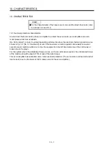
10.3.1 Dynamic brake operation
(1) Calculation of coasting distance
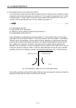
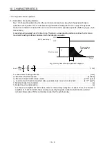
Fig. 10.3 shows the pattern in which the servo motor comes to a stop when the dynamic brake is
operated. Use equation 10.2 to calculate an approximate coasting distance to a stop. The dynamic
brake time constant
τ
varies with the servo motor and machine operation speeds. (Refer to (2) (a), (b) in
this section.)
A working part generally has a friction force. Therefore, actual coasting distance will be shorter than a
maximum coasting distance calculated with the following equation.
V
0
OFF
ON
Machine speed
t
e
Time
EM1 (Forced stop 1)
Dynamic brake
time constant
τ
Fig. 10.3 Dynamic brake operation diagram
L
max
=
60
V
0
•
t
e
+
J
M
1 + J
L
··························································································· (10.2)
L
max
: Maximum coasting distance ······················································································ [mm]
V
0
: Machine's fast feed speed ····················································································· [mm/min]
J
M
: Moment of inertia of the servo motor ··································································· [× 10
-4
kg•m
2
]
J
L
: Load moment of inertia converted into equivalent value on servo motor shaft ·············· [× 10
-4
kg•m
2
]
τ
: Dynamic brake time constant ···························································································· [s]
t
e
: Delay time of control section ···························································································· [s]
For the servo amplifier of 7 kW or less, there is internal relay delay time of about 10 ms. For the servo
amplifier of 11 kW to 22 kW, there is delay caused by magnetic contactor built into the external
dynamic brake (about 50 ms) and delay caused by the external relay.
Summary of Contents for MR-J4-100B(-RJ)
Page 17: ...8 MEMO ...
Page 143: ...4 STARTUP 4 20 MEMO ...
Page 199: ...5 PARAMETERS 5 56 MEMO ...
Page 227: ...6 NORMAL GAIN ADJUSTMENT 6 28 MEMO ...
Page 281: ...8 TROUBLESHOOTING 8 16 MEMO ...
Page 303: ...9 DIMENSIONS 9 22 MEMO ...
Page 319: ...10 CHARACTERISTICS 10 16 MEMO ...
Page 429: ...11 OPTIONS AND PERIPHERAL EQUIPMENT 11 110 MEMO ...
Page 435: ...12 ABSOLUTE POSITION DETECTION SYSTEM 12 6 MEMO ...
Page 483: ...14 USING A LINEAR SERVO MOTOR 14 34 MEMO ...
Page 531: ...16 FULLY CLOSED LOOP SYSTEM 16 26 MEMO ...
Page 613: ...17 APPLICATION OF FUNCTIONS 17 82 MEMO ...
Page 654: ...APPENDIX App 41 ...

