APPENDIX
App. - 8
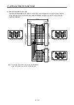
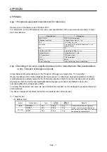
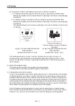
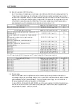
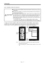
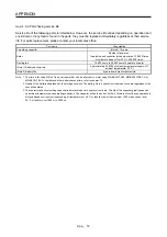
(d) Grounding
To prevent an electric shock, always connect the protective earth (PE) terminal (marked ) of the
servo amplifier to the protective earth (PE) of the cabinet. Do not connect two grounding cables to
the same protective earth (PE) terminal. Always connect cables to the terminals one-to-one.
This product can cause a DC current in the protective earthing conductor. To protect direct/indirect
contact using an earth-leakage current breaker (RCD), only an RCD of type B can be used for the
power supply side of the product.
The MR-J4-700_4 is high protective earthing conductor current equipment, the minimum size of the
protective earthing conductor must comply with the local safety regulations.
PE
terminals
PE
terminals
(2) EU compliance
The MR-J4 servo amplifiers are designed to comply with the following directions to meet requirements
for mounting, using, and periodic technical inspections: Machinery directive (2006/42/EC), EMC directive
(2014/30/EU), Low-voltage directive (2014/35/EU), and RoHS directive (2011/65/EU).
(a) EMC requirement
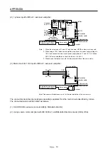
MR-J4 servo amplifiers comply with category C3 in accordance with EN 61800-3. As for I/O wires
(max. length 10 m. However, 3 m for STO cable for CN8.) and encoder cables (max. length 50 m),
use shielded wires and ground the shields. Install an EMC filter and surge protector on the primary
side for input and output of 200 V class and for output of 400 V class servo amplifiers. In addition,
use a line noise filter for outputs of the 11 kW and 15 kW of 400 V class servo amplifiers. The
following shows recommended products.
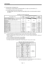
EMC filter: Soshin Electric HF3000A-UN series, TF3000C-TX series, COSEL FTB series
Surge protector: Okaya Electric Industries RSPD series
Line noise filter: Mitsubishi Electric FR-BLF
MR-J4 Series are not intended to be used on a low-voltage public network which supplies domestic
premises; radio frequency interference is expected if used on such a network. The installer shall
provide a guide for Installation and use, including recommended mitigation devices. To avoid the risk
of crosstalk to signal cables, the installation instructions shall either recommend that the power
interface cable be segregated from signal cables.
Use the DC power supply installed with the amplifiers in the same cabinet. Do not connect the other
electric devices to the DC power supply.
(b) For Declaration of Conformity (DoC)
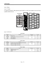
Hereby, MITSUBISHI ELECTRIC EUROPE B.V. declares that the servo amplifiers are in compliance
with the necessary requirements and standards (2006/42/EC, 2014/30/EU, 2014/35/EU and 2011/
65/EU). For the copy of Declaration of Conformity, contact your local sales office.
Summary of Contents for MR-J4-100B(-RJ)
Page 17: ...8 MEMO ...
Page 143: ...4 STARTUP 4 20 MEMO ...
Page 199: ...5 PARAMETERS 5 56 MEMO ...
Page 227: ...6 NORMAL GAIN ADJUSTMENT 6 28 MEMO ...
Page 281: ...8 TROUBLESHOOTING 8 16 MEMO ...
Page 303: ...9 DIMENSIONS 9 22 MEMO ...
Page 319: ...10 CHARACTERISTICS 10 16 MEMO ...
Page 429: ...11 OPTIONS AND PERIPHERAL EQUIPMENT 11 110 MEMO ...
Page 435: ...12 ABSOLUTE POSITION DETECTION SYSTEM 12 6 MEMO ...
Page 483: ...14 USING A LINEAR SERVO MOTOR 14 34 MEMO ...
Page 531: ...16 FULLY CLOSED LOOP SYSTEM 16 26 MEMO ...
Page 613: ...17 APPLICATION OF FUNCTIONS 17 82 MEMO ...
Page 654: ...APPENDIX App 41 ...

