3. SIGNALS AND WIRING
3 - 22
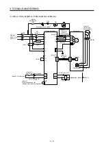
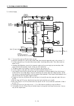
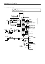
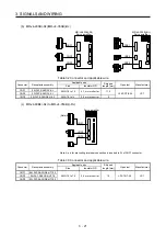
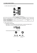
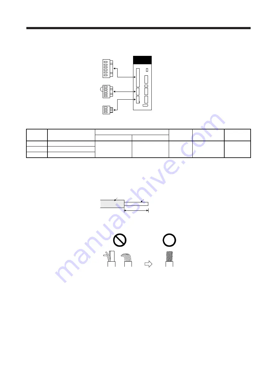
(d) MR-J4-10B1(-RJ) to MR-J4-40B1(-RJ)
CNP2
CNP1
CNP3
Servo amplifier
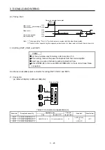
Table 3.4 Connector and applicable wire
Connector Receptacle
assembly
Applicable wire
Stripped
length [mm]
Open tool
Manufacturer
Size Insulator
OD
CNP1 06JFAT-SAXGDK-H7.5
AWG 18 to 14
3.9 mm or shorter
9
J-FAT-OT (N)
or
J-FAT-OT
JST
CNP2 05JFAT-SAXGDK-H5.0
CNP3 03JFAT-SAXGDK-H7.5
(2) Cable connection procedure
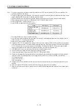
(a) Fabrication on cable insulator
Refer to table 3.1 to 3.4 for stripped length of cable insulator. The appropriate stripped length of
cables depends on their type, etc. Set the length considering their status.
Insulator
Core
Stripped length
Twist strands lightly and straighten them as follows.
Loose and bent strands
Twist and straighten
the strands.
Summary of Contents for MR-J4-100B(-RJ)
Page 17: ...8 MEMO ...
Page 143: ...4 STARTUP 4 20 MEMO ...
Page 199: ...5 PARAMETERS 5 56 MEMO ...
Page 227: ...6 NORMAL GAIN ADJUSTMENT 6 28 MEMO ...
Page 281: ...8 TROUBLESHOOTING 8 16 MEMO ...
Page 303: ...9 DIMENSIONS 9 22 MEMO ...
Page 319: ...10 CHARACTERISTICS 10 16 MEMO ...
Page 429: ...11 OPTIONS AND PERIPHERAL EQUIPMENT 11 110 MEMO ...
Page 435: ...12 ABSOLUTE POSITION DETECTION SYSTEM 12 6 MEMO ...
Page 483: ...14 USING A LINEAR SERVO MOTOR 14 34 MEMO ...
Page 531: ...16 FULLY CLOSED LOOP SYSTEM 16 26 MEMO ...
Page 613: ...17 APPLICATION OF FUNCTIONS 17 82 MEMO ...
Page 654: ...APPENDIX App 41 ...

