


17. APPLICATION OF FUNCTIONS
17 - 32
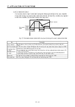
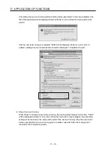
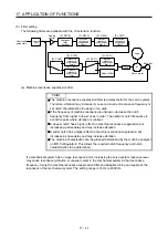
b) Amplifier command method
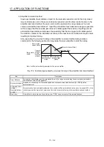
Input a permissible travel distance. Input it in the load-side resolution unit for the fully closed
loop control mode, and in the servo motor-side resolution unit for other control modes. In the
amplifier command method, the servo motor will be operated in a range between "current
value ± permissible travel distance". Input the permissible travel distance as large as possible
within a range that the movable part does not collide against the machine. Inputting a small
permissible travel distance decreases the possibility that the moving part will collide against
the machine. However, the estimation accuracy of the load to motor inertia ratio may be lower,
resulting in improper tuning.
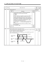
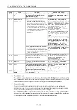
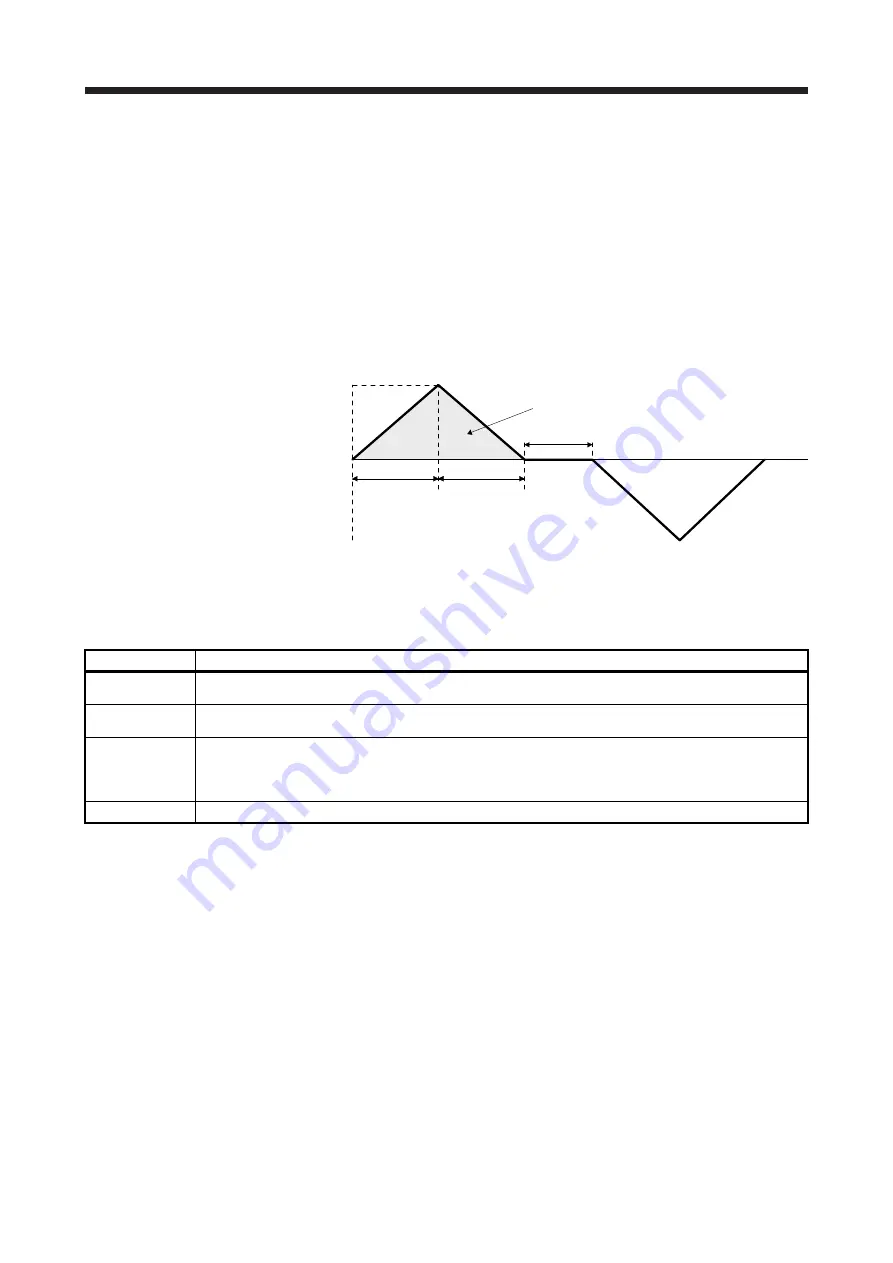
Also, executing the one-touch tuning in the amplifier command method will generate a
command for the following optimum tuning inside the servo amplifier to start the tuning.
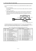
Servo motor
speed
Servo motor
speed (Note)
Forward
rotation
0 r/min
Reverse
rotation
Dwell time (Note)
Deceleration
time constant
(Note)
Travel distance (Note)
Acceleration
time constant
(Note)
Note. It will be automatically generated in the servo amplifier.
Fig. 17.2 Command generated by one-touch tuning in the amplifier command method
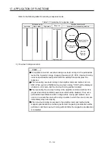
Item Description
Travel distance
An optimum travel distance will be automatically set in the range not exceeding the user-inputted permissible
travel distance with MR Configurator2.
Servo motor speed
A speed not exceeding 1/2 of the rated speed and overspeed alarm detection level ([Pr. PC08]) will be
automatically set.
Acceleration time
constant
Deceleration time
constant
An acceleration time constant/deceleration time constant will be automatically set so as not to exceed 60% of the
rated torque and the torque limit value set at the start of one-touch tuning in the amplifier command method.
Dwell time
A dwell time in which the one-touch tuning error "C004" does not occur will be automatically set.
Summary of Contents for MR-J4-100B(-RJ)
Page 17: ...8 MEMO ...
Page 143: ...4 STARTUP 4 20 MEMO ...
Page 199: ...5 PARAMETERS 5 56 MEMO ...
Page 227: ...6 NORMAL GAIN ADJUSTMENT 6 28 MEMO ...
Page 281: ...8 TROUBLESHOOTING 8 16 MEMO ...
Page 303: ...9 DIMENSIONS 9 22 MEMO ...
Page 319: ...10 CHARACTERISTICS 10 16 MEMO ...
Page 429: ...11 OPTIONS AND PERIPHERAL EQUIPMENT 11 110 MEMO ...
Page 435: ...12 ABSOLUTE POSITION DETECTION SYSTEM 12 6 MEMO ...
Page 483: ...14 USING A LINEAR SERVO MOTOR 14 34 MEMO ...
Page 531: ...16 FULLY CLOSED LOOP SYSTEM 16 26 MEMO ...
Page 613: ...17 APPLICATION OF FUNCTIONS 17 82 MEMO ...
Page 654: ...APPENDIX App 41 ...