13. USING STO FUNCTION
13 - 5
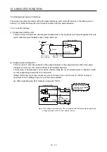
13.2.2 Signal (device) explanations
(1) I/O device
Signal name
Connector
pin No.
Description
I/O
division
STOCOM
CN8-3
Common terminal for input signal of STO1 and STO2
DI-1
STO1
CN8-4
Inputs STO state 1.
STO state (base shut-off): Open between STO1 and STOCOM.
STO release state (in driving): Close between STO1 and STOCOM.
Be sure to turn off STO1 after the servo motor stops by the servo-off state or with forced
stop deceleration by turning off EM2 (Forced stop 2).
DI-1
STO2
CN8-5
Inputs STO state 2.
STO state (base shut-off): Open between STO2 and STOCOM.
STO release state (in driving): Close between STO2 and STOCOM.
Be sure to turn off STO2 after the servo motor stops by the servo-off state or with forced
stop deceleration by turning off EM2 (Forced stop 2).
DI-1
TOFCOM
CN8-8
Common terminal for monitor output signal in STO state
DO-1
TOFB1
CN8-6
Monitor output signal in STO1 state
STO state (base shut-off): Between TOFB1 and TOFCOM is closed.
STO release state (in driving): Between TOFB1 and TOFCOM is opened.
DO-1
TOFB2
CN8-7
Monitor output signal in STO2 state
STO state (base shut-off): Between TOFB2 and TOFCOM is closed.
STO release state (in driving): Between TOFB2 and TOFCOM is opened.
DO-1
(2) Signals and STO state
The following table shows the TOFB and STO states when the power is on in normal state and STO1
and STO2 are on (closed) or off (opened).
Input signal
State
STO1 STO2
Between TOFB1 and TOFCOM
(Monitoring STO1 state)
Between TOFB2 and TOFCOM
(Monitoring STO2 state)
Between TOFB1 and TOFB2
(Monitoring STO state of servo
amplifier)
Off
Off
On: STO state (base circuit shut-off) On: STO state (base circuit shut-off) On: STO state (base circuit shut-off)
Off
On
On: STO state (base circuit shut-off) Off: STO release state
Off: STO state (base circuit shut-off)
On
Off
Off: STO release state
On: STO state (base circuit shut-off) Off: STO state (base circuit shut-off)
On
On
Off: STO release state
Off: STO release state
Off: STO release state
(3) Test pulse of STO input signal
Set the test pulse off time inputted from outside to 1 ms or less.
13.2.3 How to pull out the STO cable
The following shows how to pull out the STO cable from the CN8 connector of the servo amplifier.
1)
2)
While pressing knob 1) of the STO cable plug in the
direction of the arrow, pull out the plug 2).
Summary of Contents for MR-J4-100B(-RJ)
Page 17: ...8 MEMO ...
Page 143: ...4 STARTUP 4 20 MEMO ...
Page 199: ...5 PARAMETERS 5 56 MEMO ...
Page 227: ...6 NORMAL GAIN ADJUSTMENT 6 28 MEMO ...
Page 281: ...8 TROUBLESHOOTING 8 16 MEMO ...
Page 303: ...9 DIMENSIONS 9 22 MEMO ...
Page 319: ...10 CHARACTERISTICS 10 16 MEMO ...
Page 429: ...11 OPTIONS AND PERIPHERAL EQUIPMENT 11 110 MEMO ...
Page 435: ...12 ABSOLUTE POSITION DETECTION SYSTEM 12 6 MEMO ...
Page 483: ...14 USING A LINEAR SERVO MOTOR 14 34 MEMO ...
Page 531: ...16 FULLY CLOSED LOOP SYSTEM 16 26 MEMO ...
Page 613: ...17 APPLICATION OF FUNCTIONS 17 82 MEMO ...
Page 654: ...APPENDIX App 41 ...


