16. FULLY CLOSED LOOP SYSTEM
16 - 11
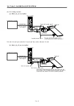
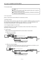
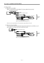
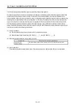
(3) Selection of load-side encoder communication method
The communication method changes depending on the load-side encoder type. Refer to table 1.1 and
"Linear Encoder Instruction Manual" for the communication method for each load-side encoder.
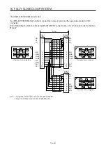
Select the cable to be connected to CN2L connector in [Pr. PC26].
0 0 0
[Pr. PC26]
Load-side encoder cable communication method selection
0: Two-wire type
1: Four-wire type
When using a load-side encoder of A/B/Z-phase differential output method, set "0".
Incorrect setting will trigger [AL. 70] and [AL. 71]. Setting "1" while
using a servo amplifier other than MR-J4-_B_-RJ will trigger [AL. 37].
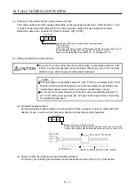
(4) Setting of load-side encoder polarity
CAUTION
Do not set an incorrect direction to "Encoder pulse count polarity selection" in [Pr.
PC27]. An abnormal operation and a machine collision may occur if an incorrect
direction is set, which cause a fault and parts damaged.
POINT
"Encoder pulse count polarity selection" in [Pr. PC27] is not related to [Pr. PA14
Rotation direction selection]. Make sure to set the parameter according to the
relationships between servo motor and linear encoder/rotary encoder.
Do not set an incorrect direction to "Encoder pulse count polarity selection" in
[Pr. PC27]. Doing so may cause [AL. 42 Fully closed loop control error] during
the positioning operation.
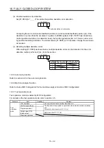
(a) Parameter setting method
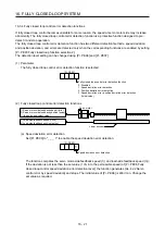
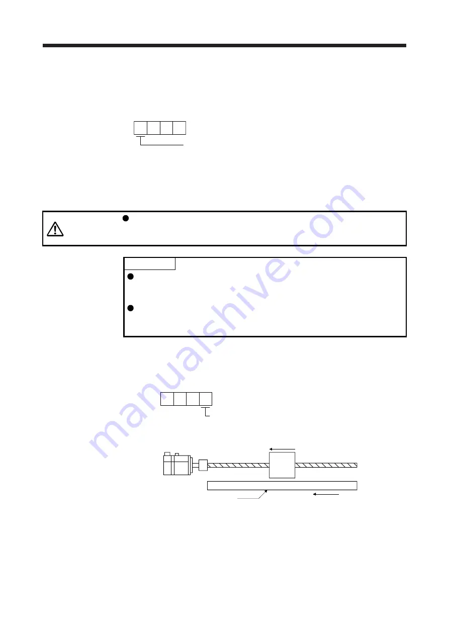
Set the load-side encoder polarity to be connected to CN2L connector in order to match the CCW
direction of servo motor and the increasing direction of load-side encoder feedback.
0 0 0
[Pr. PC27]
Encoder pulse count polarity selection
0: Load-side encoder pulse increasing direction in the servo motor CCW
1: Load-side encoder pulse decreasing direction in the servo motor CCW
Servo motor
Linear encoder
Servo motor CCW direction
Address increasing direction of linear encoder
(b) How to confirm the load-side encoder feedback direction
For the way of confirming the load-side encoder feedback direction, refer to (6) in this section.
Summary of Contents for MR-J4-100B(-RJ)
Page 17: ...8 MEMO ...
Page 143: ...4 STARTUP 4 20 MEMO ...
Page 199: ...5 PARAMETERS 5 56 MEMO ...
Page 227: ...6 NORMAL GAIN ADJUSTMENT 6 28 MEMO ...
Page 281: ...8 TROUBLESHOOTING 8 16 MEMO ...
Page 303: ...9 DIMENSIONS 9 22 MEMO ...
Page 319: ...10 CHARACTERISTICS 10 16 MEMO ...
Page 429: ...11 OPTIONS AND PERIPHERAL EQUIPMENT 11 110 MEMO ...
Page 435: ...12 ABSOLUTE POSITION DETECTION SYSTEM 12 6 MEMO ...
Page 483: ...14 USING A LINEAR SERVO MOTOR 14 34 MEMO ...
Page 531: ...16 FULLY CLOSED LOOP SYSTEM 16 26 MEMO ...
Page 613: ...17 APPLICATION OF FUNCTIONS 17 82 MEMO ...
Page 654: ...APPENDIX App 41 ...

