background image


User

s Manual 

For 

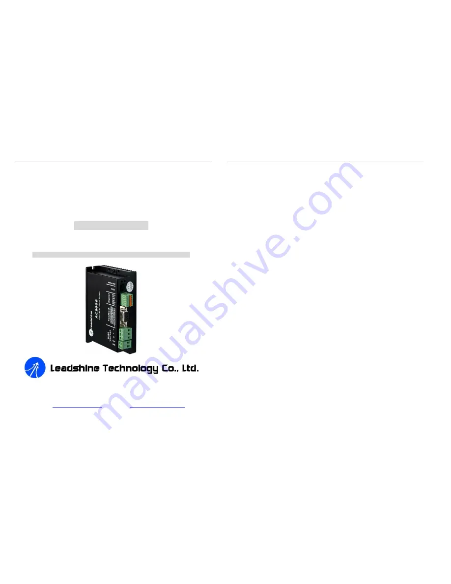
ACS606 

Digital AC Servo Drive 

Revision 1.0 

©

2009 All Rights Reserved 

Attention: Please read this manual carefully before using the drive! 


3/F, Block 2, Nanyou Tianan Industrial Park, Nanshan Dist, Shenzhen, China 

Tel: (86)755-26434369      Fax: (86)755-26402718 

URL: 

www.leadshine.com

      E-Mail: 

[email protected]


The content in this manual has been carefully prepared and is believed to be accurate, 

but no responsibility is assumed for inaccuracies. 

Leadshine reserves the right to make changes without further notice to any products 

herein  to  improve  reliability,  function  or  design.  Leadshine  does  not  assume  any 

liability  arising  out  of  the  application  or  use  of  any  product  or  circuit  described 

herein; neither does it convey any license under its patent rights of others.   

Leadshine

s  general  policy  does  not  recommend  the  use  of  its  products  in  life 

support or aircraft applications wherein a failure or malfunction of the product may 

directly  threaten  life  or  injury.  According  to  Leadshine

s  terms  and  conditions  of 

sales,  the  user  of  Leadshine

s  products  in  life  support  or  aircraft  applications 

assumes all risks of such use and indemnifies Leadshine against all damages. 


©

2009 by Leadshine Technology Company Limited. 

All Rights Reserved

Summary of Contents for ACS606

Page 1: ...o any products herein to improve reliability function or design Leadshine does not assume any liability arising out of the application or use of any product or circuit described herein neither does it convey any license under its patent rights of others Leadshine s general policy does not recommend the use of its products in life support or aircraft applications wherein a failure or malfunction of...

Page 2: ...tions and Noise Prevention 11 Wire Gauge 11 Cable Routing 12 Contents Tel 86 755 26434369 II Website www leadshine com Twisted Wires 12 Cable Shielding 12 System Grounding 12 Power Supply Connection 13 5 Tuning the Servo 13 Testing the Servo 13 Tuning the Servo 14 6 PC window based Tuning Using ProTuner 16 Introduction to ProTuner 16 Before Tuning 16 ProTuner Installation 16 Hardware Configuration...

Page 3: ...ith 32 bit DSP based on advanced control algorithm Since its input commands are PUL DIR signals the users can upgrade stepping drives to the ACS606 without changing control systems The ACS606 can offer high precision high speed and high reliability performance and widely used in inkjet printers engraving machines and etc A built in controller can be used for testing and tuning PC based and handhel...

Page 4: ...rformance Specifications with BLM Series Motors l Position following error 1 count l Velocity accuracy 2rpm l Maximum acceleration speed No Load 80 rpm ms2 l Maximum speed 3000 rpm l Allowable low speed reaches1 rpm l Positioning accuracy 1 count l Suitable for 18 60 VDC AC DC servo motors A AC CS S6 60 06 6 D Di ig gi it ta al l A AC C S Se er rv vo o d dr ri iv ve e M Ma an nu ua al l R Re ev v1...

Page 5: ...y for STU O 3 TxD RS232 transmit O 4 GND Ground GND 5 RxD RS232 receive I 6 NC Not connected High Voltage Connector Pin Signal Description I O 1 U Motor phase U O 2 V Motor phase V O 3 W Motor phase W O 4 Vdc DC power Input 18 60VDC I 5 GND Power Ground GND More about I O Signals Signal Description PUL PUL Pulse input signal In single pulse pulse direction mode this input represents pulse signal e...

Page 6: ...mon anode outputs Figure 2 Connections to controller with differential outputs Figure 3 connections to controller with Common Anode outputs A AC CS S6 60 06 6 D Di ig gi it ta al l A AC C S Se er rv vo o d dr ri iv ve e M Ma an nu ua al l R Re ev v1 1 0 0 Tel 86 755 26434369 7 Website www leadshine com Encoder and Hall Sensor Connections The ACS606 can accept both incremental encoder and hall effe...

Page 7: ...ction of the ACS606 is shown as Figure 10 Please consult Control Signal Connections and Encoder and Hall Sensor Connections for more information about controller and encoder connections A AC CS S6 60 06 6 D Di ig gi it ta al l A AC C S Se er rv vo o d dr ri iv ve e M Ma an nu ua al l R Re ev v1 1 0 0 Tel 86 755 26434369 9 Website www leadshine com Figure 10 Typical connection of the ACS606 4 Servo...

Page 8: ...the PWM cycle but not during the OFF duration Therefore the average current withdrawn from power supply is considerably less than motor current For example two 3A motors can be well supplied by one power supply of 4A rating A AC CS S6 60 06 6 D Di ig gi it ta al l A AC C S Se er rv vo o d dr ri iv ve e M Ma an nu ua al l R Re ev v1 1 0 0 Tel 86 755 26434369 11 Website www leadshine com Selecting S...

Page 9: ...g repetitive links to PE creating ground loops which is a frequent source of noise Central point grounding should also A AC CS S6 60 06 6 D Di ig gi it ta al l A AC C S Se er rv vo o d dr ri iv ve e M Ma an nu ua al l R Re ev v1 1 0 0 Tel 86 755 26434369 13 Website www leadshine com be applied to cable shielding shields should be open on one end and grounded on the other Close attention should als...

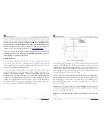
Page 10: ...side of its target It s called UNDER DAMPED status See Figure 11 This oscillation must be damped but too much damping will cause the response to be sluggish namely cause the system to get into an OVER DAMPED state When we tune a servo we are trying to achieve the fastest response with little or no overshoot namely get a CRITICALLY DAMPED response A AC CS S6 60 06 6 D Di ig gi it ta al l A AC C S S...

Page 11: ...and etc The most important feature is ProTuner offers the numeric method for tuning position loop parameters Kp Kd Ki and give a visualization result synchronously for users to evaluate the performance of the system Before Tuning ProTuner Installation The ProTuner is windows based setup software for tuning Leadshine s digital drives It can run in windows systems including Win95 Win98 WindowsNT Win...

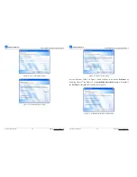
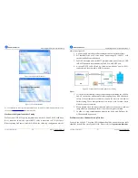
Page 12: ...S6 60 06 6 D Di ig gi it ta al l A AC C S Se er rv vo o d dr ri iv ve e M Ma an nu ua al l R Re ev v1 1 0 0 Tel 86 755 26434369 19 Website www leadshine com Figure 16 Shortcut folder setting Set the Shortcut Folder in Figure 16 and continue to install the ProTuner by following Figure 17 and Figure 18 An Installation Successful window will appear if the ProTuner is installed successfully See Figure...

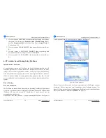
Page 13: ...ervo motor power range 10 200W with encoder and hall sensor feedback 3 Table PC Notebook with one RS232 communication port at least or a USB to RS232 adapter Recommend using Table PC with RS232 port 4 A special RS232 cable offered by Leadsine in which one end is a RJ 11 connector and the other end is a DB9 connector Figure 20 Configuration and connections before Tuning Note 1 If it is the first in...

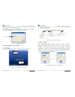
Page 14: ...lect Status Bar Main Menu A AC CS S6 60 06 6 D Di ig gi it ta al l A AC C S Se er rv vo o d dr ri iv ve e M Ma an nu ua al l R Re ev v1 1 0 0 Tel 86 755 26434369 23 Website www leadshine com 2 Menu Bar and Submenu Figure 23 Menu of ProTuner for the ACS606 Communication Setup Select Option ComConfig a dialogue window for setting the RS232 communication parameters would appear as figure 24 Select a ...

Page 15: ...g gi it ta al l A AC C S Se er rv vo o d dr ri iv ve e M Ma an nu ua al l R Re ev v1 1 0 0 Tel 86 755 26434369 25 Website www leadshine com function and when open the current tuning window by selecting Tuning CurrentLoop a password input window will appear Leadshine just offers password to some customers for tuning current loop while most of customers just need to tune the position loop parameters...

Page 16: ...h Kp of current loop Kp 24000 Begin to Overshoot Large Overshoot A AC CS S6 60 06 6 D Di ig gi it ta al l A AC C S Se er rv vo o d dr ri iv ve e M Ma an nu ua al l R Re ev v1 1 0 0 Tel 86 755 26434369 27 Website www leadshine com Figure 29 Step response with better Kp and Ki of current loop Kp 17000 Ki 400 5 At that moment Kp and Ki of the current loop is nearly optimum To reduce the raise time pl...

Page 17: ... Current Torque mode Position around Torque This mode is most common in point to point applications where actual motion between start and end point is not very critical In this case velocity loop tuning can be avoided This can be advantageous if the velocity feedback is poor e g low resolution encoder poor encoder quadrature In this case the tuning process requires that the position loop proportio...

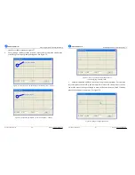
Page 18: ...self test result is shown in Figure 33 A AC CS S6 60 06 6 D Di ig gi it ta al l A AC C S Se er rv vo o d dr ri iv ve e M Ma an nu ua al l R Re ev v1 1 0 0 Tel 86 755 26434369 31 Website www leadshine com Figure 33 Position following error curve and velocity curve Kp 2000 Ki 0 and Kd 1000 It s very easy to see from the velocity curve Green line that the system is under damped This will cause system...

Page 19: ...l l R Re ev v1 1 0 0 Tel 86 755 26434369 33 Website www leadshine com Although a smooth velocity curve have been gotten in Figure 35 we can see that the position following error is still too large to accept And this can be improved by increasing Ki value See Figure 36 However we can see the system response in Figure 35 is already Over Damped namely too much damping has caused the response to be sl...

Page 20: ...e er rv vo o d dr ri iv ve e M Ma an nu ua al l R Re ev v1 1 0 0 Tel 86 755 26434369 35 Website www leadshine com Increase Kd can reduce velocity overshoot and get a better velocity curve in as shown in Figure 39 Figure 39 Position following error curve and velocity curve Kp 6000 Ki 500 and Kd 8500 Since position following error is still large during constant speed period in Figure 39 we try to in...

Page 21: ...v vo o d dr ri iv ve e M Ma an nu ua al l R Re ev v1 1 0 0 Tel 86 755 26434369 37 Website www leadshine com Figure 42 Position following error curve and velocity curve Kp 6000 Ki 1600 and Kd 8500 Increasing Kp a little and reducing Ki to 1400 can achieve a faster response with little overshoot namely get a response close to Critically Damped response See Figure 43 Remember to download the paramete...

Page 22: ...vo system is OVER DAMPED then decrease Kd or increase Kp or Ki A AC CS S6 60 06 6 D Di ig gi it ta al l A AC C S Se er rv vo o d dr ri iv ve e M Ma an nu ua al l R Re ev v1 1 0 0 Tel 86 755 26434369 39 Website www leadshine com Upload and Download Data Download Data to EEPROM A built in EEPROM in the ACS606 is used to save the configuration data Every time when you finish configuration or get sati...

Page 23: ...n See figure 46 for more detail Figure 45 Upload and download window Download Data to Device When communication between ProTuner and the ACS606 is established you can open a configuration file and download the data from the file to the drive See figure 47 for more details Select folder Files list in folder File name and path Save on harddisk Download to EEPROM A AC CS S6 60 06 6 D Di ig gi it ta a...

Page 24: ...and negative movement A AC CS S6 60 06 6 D Di ig gi it ta al l A AC C S Se er rv vo o d dr ri iv ve e M Ma an nu ua al l R Re ev v1 1 0 0 Tel 86 755 26434369 43 Website www leadshine com CurveSetting tab In Tuning PositionLoop CurveSetting tab the user can choose curves displayed in digital scope of Position Loop Tuning window and DigitalMonitor window and set their Trace Time These curves include...

Page 25: ...g Erase Current Err button and all error events can be reset by clicking Erase All button A AC CS S6 60 06 6 D Di ig gi it ta al l A AC C S Se er rv vo o d dr ri iv ve e M Ma an nu ua al l R Re ev v1 1 0 0 Tel 86 755 26434369 45 Website www leadshine com Figure 49 Error check window OverCurrent Over current Protection Protection will be activated when continuous current exceeds 24A OverVoltage Ove...

Page 26: ...ctronic Denominator of Electronic Position following error limit A AC CS S6 60 06 6 D Di ig gi it ta al l A AC C S Se er rv vo o d dr ri iv ve e M Ma an nu ua al l R Re ev v1 1 0 0 Tel 86 755 26434369 47 Website www leadshine com Position following Error Limit The ACS606 will activate a position following error if position error between command and encoder feedback exceeds the setting limit value ...

Page 27: ...tection No encoder feedback signals or wrong encoder hall sensor feedback signals will activate this protection RED LED will turn on five times within each periodic time 5 s Position Following Error Protection When position following error reaches Position Following Error Limit parameter A AC CS S6 60 06 6 D Di ig gi it ta al l A AC C S Se er rv vo o d dr ri iv ve e M Ma an nu ua al l R Re ev v1 1...

Page 28: ...s overview and typical connections A AC CS S6 60 06 6 D Di ig gi it ta al l A AC C S Se er rv vo o d dr ri iv ve e M Ma an nu ua al l R Re ev v1 1 0 0 Tel 86 755 26434369 51 Website www leadshine com Figure 53 ACS606 accessories overview and connections with lengthening cable More Information about ACS606 Accessories ProTuner Description PC based configuration tuning software Order Standard Access...

Page 29: ...drive and Handheld configuration tuning unit STU ACS Order One STU ACS needs at least one A AC CS S6 60 06 6 D Di ig gi it ta al l A AC C S Se er rv vo o d dr ri iv ve e M Ma an nu ua al l R Re ev v1 1 0 0 Tel 86 755 26434369 53 Website www leadshine com 6 pin Control signal Connector Description Self locked connector for control signals include PUL PUL DIR and DIR ENA ENA Order Standard Accessory...

Page 30: ... warranty shall not apply to defects resulting from improper or inadequate handling by customer improper or inadequate customer wiring unauthorized modification or misuse or operation beyond the electrical specifications of the product and or operation beyond environmental specifications for the product OBTAINING WARRANTY SERVICE To obtain warranty service a returned material authorization number ...

Page 31: ...ng the warranty period e mail customer service at tech leadshine com to obtain a returned material authorization number RMA before returning product for service Please include a written description of the problem along with contact name and address Send failed product to distributor in your area or Leadshine Technology Co Ltd Floor 3 Block 2 Tianan Industrial Park Nanshan Dist Shenzhen China Also ...

Reviews: