


A
A
C
C
S
S
6
6
0
0
6
6
D
D
i
i
g
g
i
i
t
t
a
a
l
l
A
A
C
C
S
S
e
e
r
r
v
v
o
o
d
d
r
r
i
i
v
v
e
e
M
M
a
a
n
n
u
u
a
a
l
l
R
R
e
e
v
v
1
1
.
.
0
0
Tel: (86)755-26434369
28
Website: www.leadshine.com
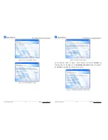
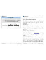
Position Loop Tuning
Position Loop Introduction
Position loop tuning is dependant on the mechanical load, and therefore will change
with any mechanical system changes. Position loop tuning should be performed with
the motor installed in the system. The position loop can be closed around velocity or
torque mode (depending on whether the velocity loop is enabled or disabled). If it is
closed around velocity mode, the position loop algorithm output becomes the new
velocity set point. If it is closed around torque mode, the position loop algorithm
output becomes the new torque set point. There are some important differences in the
tuning process and application of these two approaches.
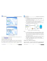
Position around Velocity:
This mode is most common in "contouring" application,
where a position trajectory must be tracked very closely. The velocity loop provides
additional "stiffness", and keeps the dynamic position errors minimal, since the
system now reacts to not just position errors, but also velocity errors (which can be
interpreted as position error changes). It is important to start with a stable yet
responsive velocity loop. Typically, it is sufficient to just use the position loop
proportional gain. Feedforward gain can be added to improve tracking performance
(i.e. minimize the difference between commanded and actual position). The velocity
loop is disabled in current version ACS606, and it adopts
Position around Current
(Torque) mode.
Position around Torque:
This mode is most common in point-to-point applications,
where actual motion between start and end point is not very critical. In this case,
velocity loop tuning can be avoided. This can be advantageous if the velocity
feedback is poor (e.g. low resolution encoder, poor encoder quadrature.).
In this case,
the tuning process requires that the position loop proportional and derivative
gain are increased simultaneously, unless the system has sufficient friction, in
which case no derivative gain is necessary. Once a stable response is achieved,
integral gain can be added to improve stiffness.
It is best to use a step command
A
A
C
C
S
S
6
6
0
0
6
6
D
D
i
i
g
g
i
i
t
t
a
a
l
l
A
A
C
C
S
S
e
e
r
r
v
v
o
o
d
d
r
r
i
i
v
v
e
e
M
M
a
a
n
n
u
u
a
a
l
l
R
R
e
e
v
v
1
1
.
.
0
0
Tel: (86)755-26434369
29
Website: www.leadshine.com
with the profiler enabled as a reference signal during tuning.
Drive tuning is a multi-step process that involves proper tuning of up to three different
servo loops, namely current loop, velocity loop and position loop. You can either tune
the position loop around the velocity loop, or around the current loop. Generally, it is
much easier to tune a position loop around a velocity loop because only the
proportional gain is needed. When tuning position around the current loop, a high
derivative gain may be necessary on top of both proportional and integral gains.
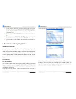
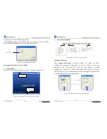
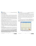
Start to Tune
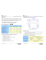
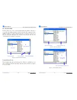
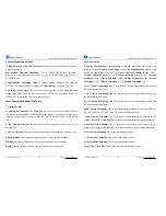
Set the parameters and select the curves displayed in
Digital Monitor
before
starting self-test and tuning. See Figure 31 and Figure 32 for the parameters for the
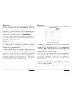
tuning in this paper. When we tune a servo, we are trying to achieve the fastest
response with little or no overshoot, namely get a Critically Damped response.
Figure 31: Self-test motion settings for the tuning


