

17. APPLICATION OF FUNCTIONS
17 - 15
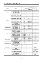
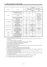
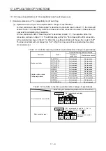
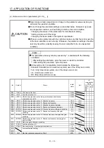
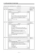
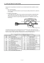
(2) Extension control 2 parameters ([Pr. PX_ _ ])
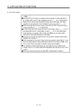
CAUTION
Never make a drastic adjustment or change to the parameter values as doing so
will make the operation unstable.
Do not change the parameter settings as described below. Doing so may cause
an unexpected condition, such as failing to start up the servo amplifier.
Changing the values of the parameters for manufacturer setting
Setting a value out of the range
Changing the fixed values in the digits of a parameter
When you write parameters with the controller, make sure that the control axis No.
of the servo amplifier is set correctly. Otherwise, the parameter settings of another
axis may be written, possibly causing the servo amplifier to be an unexpected
condition.
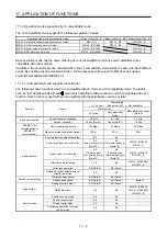
POINT
The parameter whose symbol is preceded by * is enabled with the following
conditions:
*: After setting the parameter, cycle the power or reset the controller.
**: After setting the parameter, cycle the power.
Abbreviations of J3 compatibility mode indicate the followings.
Standard: Standard (semi closed loop system) use of the rotary servo motor
Full.: Fully closed loop system use of the rotary servo motor
Lin.: Linear servo motor use
DD: Direct drive (DD) motor use
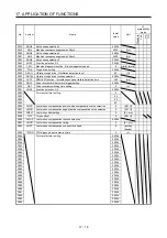
No. Symbol
Name
Initial
value
Unit
J3
compatibility
mode
Standard
F
ull.
Lin.
DD
PX01
**J3EX J3 extension function
0000h
PX02
XOP1
Function selection X-1
0000h
PX03 VRFTX Vibration suppression control tuning mode (advanced vibration
suppression control II)
0000h
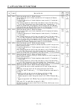
PX04
VRF21 Vibration suppression control 2 - Vibration frequency
100.0
[Hz]
PX05
VRF22 Vibration suppression control 2 - Resonance frequency
100.0
[Hz]
PX06
VRF23 Vibration suppression control 2 - Vibration frequency damping
0.00
PX07
VRF24 Vibration suppression control 2 - Resonance frequency damping
0.00
PX08 VRF21B Vibration suppression control 2 - Vibration frequency after gain switching
0.0
[Hz]
PX09 VRF22B Vibration suppression control 2 - Resonance frequency after gain
switching
0.0 [Hz]
PX10 VRF23B Vibration suppression control 2 - Vibration frequency damping after gain
switching
0.00
PX11 VRF24B Vibration suppression control 2 - Resonance frequency damping after
gain switching
0.00
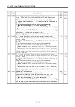
PX12
PG1B
Model loop gain after gain switching
0.0
[rad/s]
PX13
*XOP2 Function selection X-2
0001h
PX14 OTHOV One-touch tuning - Overshoot permissible level
0
[%]
PX15
For manufacturer setting
0000h
PX16
0000h
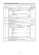
PX17
NH3
Machine resonance suppression filter 3
4500
[Hz]
Summary of Contents for MR-J4-100B(-RJ)
Page 17: ...8 MEMO ...
Page 143: ...4 STARTUP 4 20 MEMO ...
Page 199: ...5 PARAMETERS 5 56 MEMO ...
Page 227: ...6 NORMAL GAIN ADJUSTMENT 6 28 MEMO ...
Page 281: ...8 TROUBLESHOOTING 8 16 MEMO ...
Page 303: ...9 DIMENSIONS 9 22 MEMO ...
Page 319: ...10 CHARACTERISTICS 10 16 MEMO ...
Page 429: ...11 OPTIONS AND PERIPHERAL EQUIPMENT 11 110 MEMO ...
Page 435: ...12 ABSOLUTE POSITION DETECTION SYSTEM 12 6 MEMO ...
Page 483: ...14 USING A LINEAR SERVO MOTOR 14 34 MEMO ...
Page 531: ...16 FULLY CLOSED LOOP SYSTEM 16 26 MEMO ...
Page 613: ...17 APPLICATION OF FUNCTIONS 17 82 MEMO ...
Page 654: ...APPENDIX App 41 ...