5. PARAMETERS
5 - 38
No.
Symbol
Name and function
Initial
value
[unit]
Setting
range
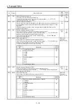
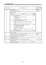
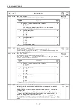
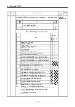
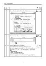
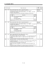
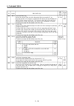
PC10
MOD2
Analog monitor 2 output
Select a signal to output to MO2 (Analog monitor 2). Refer to app. 11.3 for detection point of
output selection.
Refer to the
"Name and
function" column.
Setting
digit
Explanation
Initial
value
_ _ x x
Analog monitor 2 output selection
Refer to [Pr. PC09] for settings.
01h
_ x _ _
For manufacturer setting
0h
x _ _ _
0h
PC11
MO1
Analog monitor 1 offset
This is used to set the offset voltage of MO1 (Analog monitor 1).
0
[mV]
-999 to
999
PC12
MO2
Analog monitor 2 offset
This is used to set the offset voltage of MO2 (Analog monitor 2).
0
[mV]
-999 to
999
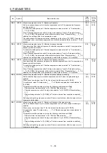
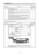
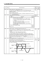
PC13 MOSDL Analog monitor - Feedback position output standard data - Low
Set a monitor output standard position (lower 4 digits) for the feedback position for when
selecting "Feedback position" for MO1 (Analog monitor 1) and MO2 (Analog monitor 2).
Monitor output standard position = [Pr. PC14] setting × 10000 + [Pr. PC13] setting
0
[pulse]
-9999 to
9999
PC14 MOSDH Analog monitor - Feedback position output standard data - High
Set a monitor output standard position (higher 4 digits) for the feedback position for when
selecting "Feedback position" for MO1 (Analog monitor 1) and MO2 (Analog monitor 2).
Monitor output standard position = [Pr. PC14] setting × 10000 + [Pr. PC13] setting
0
[10000
pulses]
-9999 to
9999
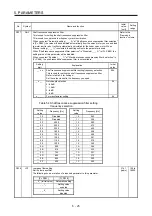
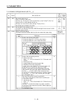
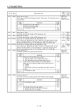
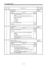
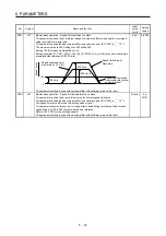
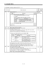
PC17 **COP4 Function selection C-4
This is used to select a home position setting condition.
Refer to the
"Name and
function" column.
Setting
digit
Explanation
Initial
value
_ _ _ x
Selection of home position setting condition
0: Need to pass servo motor Z-phase after power on
1: Not need to pass servo motor Z-phase after power on
0h
_ _ x _
Linear encoder multipoint Z-phase input function selection
When two or more reference marks exist in the fully stroke, set "1".
0: Disabled
1: Enabled
This parameter is used by servo amplifier with software version A5
or later.
0h
_ x _ _
For manufacturer setting
0h
x _ _ _
0h
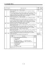
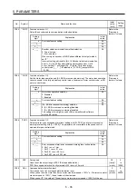
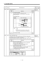
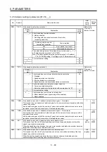
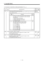
PC18
*COP5 Function selection C-5
This is used to select an occurring condition of [AL. E9 Main circuit off warning].
Refer to the
"Name and
function" column.
Setting
digit
Explanation
Initial
value
_ _ _ x
For manufacturer setting
0h
_ _ x _
0h
_ x _ _
0h
x _ _ _
[AL. E9 Main circuit off warning] selection
0: Detection with ready-on and servo-on command
1: Detection with servo-on command
0h
Summary of Contents for MR-J4-100B(-RJ)
Page 17: ...8 MEMO ...
Page 143: ...4 STARTUP 4 20 MEMO ...
Page 199: ...5 PARAMETERS 5 56 MEMO ...
Page 227: ...6 NORMAL GAIN ADJUSTMENT 6 28 MEMO ...
Page 281: ...8 TROUBLESHOOTING 8 16 MEMO ...
Page 303: ...9 DIMENSIONS 9 22 MEMO ...
Page 319: ...10 CHARACTERISTICS 10 16 MEMO ...
Page 429: ...11 OPTIONS AND PERIPHERAL EQUIPMENT 11 110 MEMO ...
Page 435: ...12 ABSOLUTE POSITION DETECTION SYSTEM 12 6 MEMO ...
Page 483: ...14 USING A LINEAR SERVO MOTOR 14 34 MEMO ...
Page 531: ...16 FULLY CLOSED LOOP SYSTEM 16 26 MEMO ...
Page 613: ...17 APPLICATION OF FUNCTIONS 17 82 MEMO ...
Page 654: ...APPENDIX App 41 ...

