


4. STARTUP
4 - 10
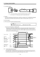
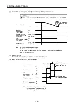
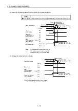
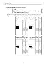
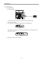
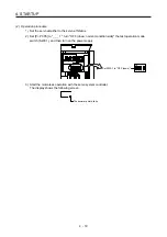
(c) Switch combination list for the control axis No. setting
POINT
Set control axis Nos. for one system. For details of the control axis No., refer to
the servo system controller user's manual.
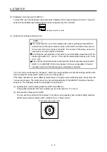
The following lists show the setting combinations of the auxiliary axis number setting switches and
the axis selection rotary switch.
Auxiliary axis number
setting switch
Axis
selection
rotary
switch
Control
axis No.
Auxiliary axis number
setting switch
Axis
selection
rotary
switch
Control
axis No.
1
ON
2 3 4
0 1
1
ON
2 3 4
0 17
1 2
1 18
2 3
2 19
3 4
3 20
4 5
4 21
5 6
5 22
6 7
6 23
7 8
7 24
8 9
8 25
9 10
9 26
A 11
A 27
B 12
B 28
C 13
C 29
D 14
D 30
E 15
E 31
F 16
F 32
Auxiliary axis number
setting switch
Axis
selection
rotary
switch
Control
axis No.
Auxiliary axis number
setting switch
Axis
selection
rotary
switch
Control
axis No.
1
ON
2 3 4
0 33
1
ON
2 3 4
0 49
1 34
1 50
2 35
2 51
3 36
3 52
4 37
4 53
5 38
5 54
6 39
6 55
7 40
7 56
8 41
8 57
9 42
9 58
A 43
A 59
B 44
B 60
C 45
C 61
D 46
D 62
E 47
E 63
F 48
F 64
Summary of Contents for MR-J4-100B(-RJ)
Page 17: ...8 MEMO ...
Page 143: ...4 STARTUP 4 20 MEMO ...
Page 199: ...5 PARAMETERS 5 56 MEMO ...
Page 227: ...6 NORMAL GAIN ADJUSTMENT 6 28 MEMO ...
Page 281: ...8 TROUBLESHOOTING 8 16 MEMO ...
Page 303: ...9 DIMENSIONS 9 22 MEMO ...
Page 319: ...10 CHARACTERISTICS 10 16 MEMO ...
Page 429: ...11 OPTIONS AND PERIPHERAL EQUIPMENT 11 110 MEMO ...
Page 435: ...12 ABSOLUTE POSITION DETECTION SYSTEM 12 6 MEMO ...
Page 483: ...14 USING A LINEAR SERVO MOTOR 14 34 MEMO ...
Page 531: ...16 FULLY CLOSED LOOP SYSTEM 16 26 MEMO ...
Page 613: ...17 APPLICATION OF FUNCTIONS 17 82 MEMO ...
Page 654: ...APPENDIX App 41 ...