
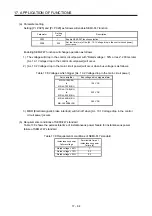
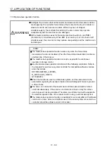

17. APPLICATION OF FUNCTIONS
17 - 74
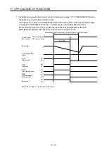
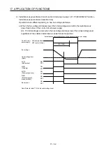
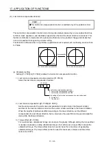
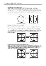
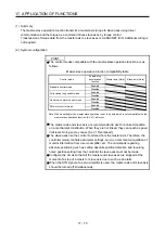
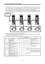
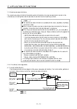
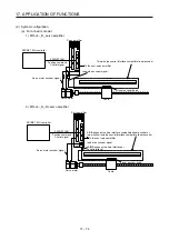
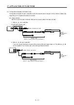
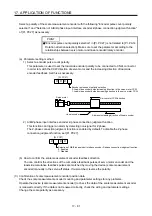
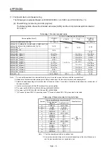
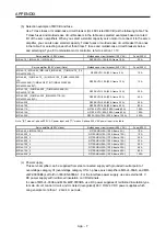
(2) System configuration
(a) For a linear encoder
1) MR-J4-_B_ servo amplifier
Servo amplifier
CN2
SSCNET III/H controller
SSCNET III/H
Position command
Control signal
Table
To the next servo amplifier
Two-wire type serial interface compatible linear encoder
Load-side encoder signal
Servo motor encoder signal
Linear encoder head
Servo motor
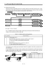
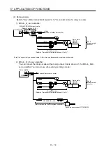
2) MR-J4-_B_-RJ servo amplifier
Servo amplifier
CN2
SSCNET III/H controller
SSCNET III/H
Position command
Control signal
Table
To the next servo amplifier
A/B/Z-phase pulse train interface compatible linear encoder or
two-wire/four-wire type serial interface compatible linear encoder
Load-side encoder signal
Servo motor encoder signal
Linear encoder head
Servo motor
CN2L
(A/B/Z-phase pulse train interface or
serial interface)
Summary of Contents for MR-J4-100B(-RJ)
Page 17: ...8 MEMO ...
Page 143: ...4 STARTUP 4 20 MEMO ...
Page 199: ...5 PARAMETERS 5 56 MEMO ...
Page 227: ...6 NORMAL GAIN ADJUSTMENT 6 28 MEMO ...
Page 281: ...8 TROUBLESHOOTING 8 16 MEMO ...
Page 303: ...9 DIMENSIONS 9 22 MEMO ...
Page 319: ...10 CHARACTERISTICS 10 16 MEMO ...
Page 429: ...11 OPTIONS AND PERIPHERAL EQUIPMENT 11 110 MEMO ...
Page 435: ...12 ABSOLUTE POSITION DETECTION SYSTEM 12 6 MEMO ...
Page 483: ...14 USING A LINEAR SERVO MOTOR 14 34 MEMO ...
Page 531: ...16 FULLY CLOSED LOOP SYSTEM 16 26 MEMO ...
Page 613: ...17 APPLICATION OF FUNCTIONS 17 82 MEMO ...
Page 654: ...APPENDIX App 41 ...