
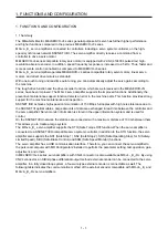
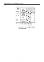
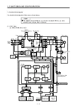
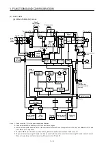
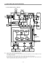
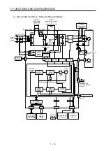
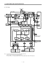
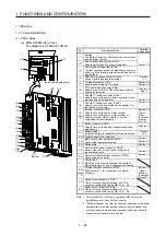
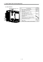
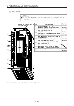
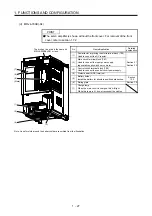

1. FUNCTIONS AND CONFIGURATION
1 - 13
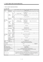
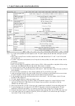
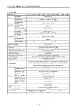
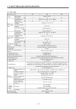
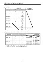
1.3 Servo amplifier standard specifications
(1) 200 V class
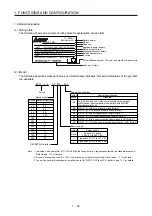
Model:
MR-J4-_(-RJ)
10B 20B 40B 60B 70B 100B 200B 350B 500B 700B 11KB 15KB 22KB
Output
Rated voltage
3-phase 170 V AC
Rated current
[A]
1.1
1.5 2.8 3.2 5.8 6.0 11.0 17.0 28.0 37.0 68.0 87.0 126.0
Main circuit
power supply
input
Voltage/
Frequency
At AC
input
3-phase or 1-phase
200 V AC to 240 V AC, 50 Hz/60 Hz
3-phase or 1-
phase 200 V
AC to 240 V
AC, 50 Hz/60
Hz (Note 13)
3-phase 200 V AC to 240 V AC, 50 Hz/60 Hz
At DC
input
(Note 16)
283 V DC to 340 V DC
Rated current
(Note 11)
[A]
0.9 1.5 2.6
3.2
(Note 6)
3.8 5.0 10.5 16.0
21.7 28.9 46.0 64.0 95.0
Permissible
voltage
fluctuation
At AC
input
3-phase or 1-phase
170 V AC to 264 V AC
3-phase or 1-
phase 170 V
AC to 264 V
AC (Note 13)
3-phase 170 V AC to 264 V AC
At DC
input
(Note 16)
241 V DC to 374 V DC
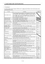
Permissible frequency
fluctuation
Within ±5%
Power supply capacity
[kVA]
Refer to section 10.2.
Inrush current
[A]
Refer to section 10.5.
Control circuit
power supply
input
Voltage/
Frequency
At AC
input
1-phase 200 V AC to 240 V AC, 50 Hz/60 Hz
At DC
input
(Note 16)
283 V DC to 340 V DC
Rated current
[A]
0.2
0.3
Permissible
voltage
fluctuation
At AC
input
1-phase 170 V AC to 264 V AC
At DC
input
(Note 16)
241 V DC to 374 V DC
Permissible frequency
fluctuation
Within ±5%
Power consumption [W]
30
45
Inrush current
[A]
Refer to section 10.5.
Interface power
supply
Voltage
24 V DC ± 10%
Current capacity
[A]
0.3 (including CN8 connector signals) (Note 1)
Control method
Sine-wave PWM control, current control method
Dynamic brake
Built-in
External option
(Note 9, 12)
SSCNET III/H communication cycle
(Note 8)
0.222 ms, 0.444 ms, 0.888 ms
Fully closed loop control
Compatible (Note 7)
Scale measurement function
Compatible (Note 10)
Load-side encoder interface (Note 5)
Mitsubishi Electric high-speed serial communication
Communication function
USB: connection to a personal computer or others (MR Configurator2-compatible)
Encoder output pulses
Compatible (A/B/Z-phase pulse)
Analog monitor
Two channels
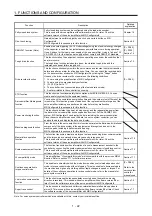
Protective functions
Overcurrent shut-off, regenerative overvoltage shut-off, overload shut-off (electronic thermal), servo motor
overheat protection, encoder error protection, regenerative error protection, undervoltage protection,
instantaneous power failure protection, overspeed protection, error excessive protection, magnetic pole
detection protection, and linear servo control fault protection
Functional safety
STO (IEC/EN 61800-5-2)
Summary of Contents for MR-J4-100B(-RJ)
Page 17: ...8 MEMO ...
Page 143: ...4 STARTUP 4 20 MEMO ...
Page 199: ...5 PARAMETERS 5 56 MEMO ...
Page 227: ...6 NORMAL GAIN ADJUSTMENT 6 28 MEMO ...
Page 281: ...8 TROUBLESHOOTING 8 16 MEMO ...
Page 303: ...9 DIMENSIONS 9 22 MEMO ...
Page 319: ...10 CHARACTERISTICS 10 16 MEMO ...
Page 429: ...11 OPTIONS AND PERIPHERAL EQUIPMENT 11 110 MEMO ...
Page 435: ...12 ABSOLUTE POSITION DETECTION SYSTEM 12 6 MEMO ...
Page 483: ...14 USING A LINEAR SERVO MOTOR 14 34 MEMO ...
Page 531: ...16 FULLY CLOSED LOOP SYSTEM 16 26 MEMO ...
Page 613: ...17 APPLICATION OF FUNCTIONS 17 82 MEMO ...
Page 654: ...APPENDIX App 41 ...