

5. PARAMETERS
5 - 20
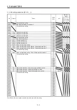
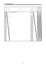
No.
Symbol
Name and function
Initial
value
[unit]
Setting
range
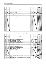
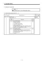
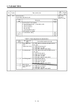
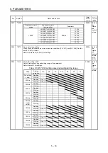
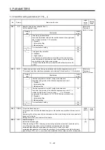
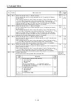
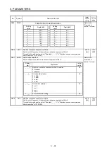
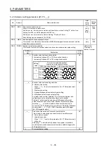
PA22
**PCS
Position control composition selection
Refer to the
"Name and
function" column.
Setting
digit
Explanation
Initial
value
_ _ _ x
For manufacturer setting
0h
_ _ x _
Super trace control selection
0: Disabled
2: Enabled
This parameter setting is used with servo amplifier with software
version B4 or later.
0h
_ x _ _
For manufacturer setting
0h
x _ _ _
Scale measurement function selection
0: Disabled
1: Used in absolute position detection system
2: Used in incremental system
The absolute position detection system cannot be used while an
incremental type encoder is used. Enabling absolute position
detection system will trigger [AL. 37 Parameter error].
Additionally, the setting is enabled only in the standard control
mode. Setting other than "0" in other operation modes triggers [AL.
37 Parameter error].
0h
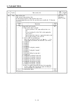
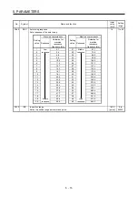
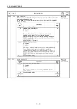
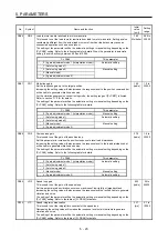
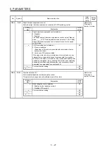
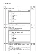
PA23
DRAT
Drive recorder arbitrary alarm trigger setting
Refer to the
"Name and
function" column.
Setting
digit
Explanation
Initial
value
_ _ x x
Alarm detail No. setting
Set the digits when you execute the trigger with arbitrary alarm
detail No. for the drive recorder function.
When these digits are "0 0", only the arbitrary alarm No. setting will
be enabled.
00h
x x _ _
Alarm No. setting
Set the digits when you execute the trigger with arbitrary alarm No.
for the drive recorder function.
When "0 0" are set, arbitrary alarm trigger of the drive recorder will
be disabled.
00h
Setting
example:
To activate the drive recorder when [AL. 50 Overload 1] occurs, set "5 0 0 0".
To activate the drive recorder when [AL. 50.3 Thermal overload error 4 during operation]
occurs, set "5 0 0 3".
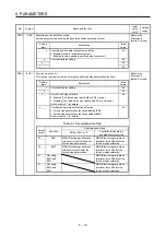
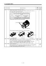
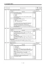
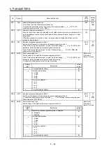
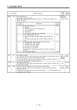
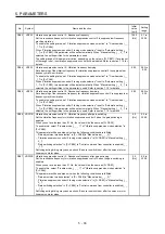
PA24
AOP4
Function selection A-4
Refer to the
"Name and
function" column.
Setting
digit
Explanation
Initial
value
_ _ _ x
Vibration suppression function selection
0: Standard mode
1: 3 inertia mode
2: Low response mode
When two low resonance frequencies are generated, select "3
inertia mode (_ _ _ 1)". When the load to motor inertia ratio exceeds
the recommended load to motor inertia ratio, select "Low response
mode (_ _ _ 2)".
When you select the standard mode or low response mode,
"Vibration suppression control 2" is not available.
When you select the 3 inertia mode, the feed forward gain is not
available.
Before changing the control mode with the controller during the 3
inertia mode or low response mode, stop the motor.
0h
_ _ x _
For manufacturer setting
0h
_ x _ _
0h
x _ _ _
0h
Summary of Contents for MR-J4-100B(-RJ)
Page 17: ...8 MEMO ...
Page 143: ...4 STARTUP 4 20 MEMO ...
Page 199: ...5 PARAMETERS 5 56 MEMO ...
Page 227: ...6 NORMAL GAIN ADJUSTMENT 6 28 MEMO ...
Page 281: ...8 TROUBLESHOOTING 8 16 MEMO ...
Page 303: ...9 DIMENSIONS 9 22 MEMO ...
Page 319: ...10 CHARACTERISTICS 10 16 MEMO ...
Page 429: ...11 OPTIONS AND PERIPHERAL EQUIPMENT 11 110 MEMO ...
Page 435: ...12 ABSOLUTE POSITION DETECTION SYSTEM 12 6 MEMO ...
Page 483: ...14 USING A LINEAR SERVO MOTOR 14 34 MEMO ...
Page 531: ...16 FULLY CLOSED LOOP SYSTEM 16 26 MEMO ...
Page 613: ...17 APPLICATION OF FUNCTIONS 17 82 MEMO ...
Page 654: ...APPENDIX App 41 ...