


8. TROUBLESHOOTING
8 - 14
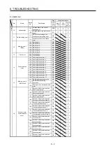
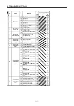
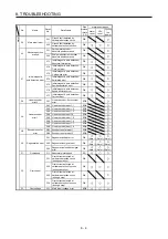
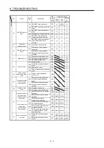
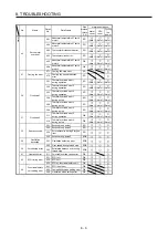
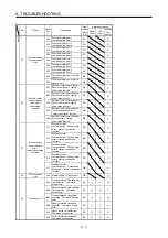
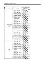
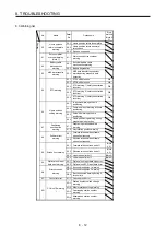
No.
Name
Detail
No.
Detail name
Stop
method
(Note 2,
3)
Warning
ED
Output watt excess
warning
ED.1 Output watt excess warning
F0
Tough drive warning
F0.1
Instantaneous power failure tough
drive warning
F0.3 Vibration tough drive warning
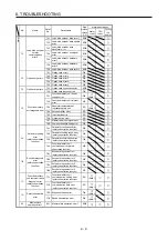
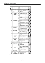
F2
Drive recorder -
Miswriting warning
F2.1
Drive recorder - Area writing time-
out warning
F2.2
Drive recorder - Data miswriting
warning
F3
Oscillation detection
warning
F3.1 Oscillation detection warning
F4 Positioning
warning
F4.4
Target position setting range error
warning
F4.6
Acceleration time constant setting
range error warning
F4.7
Deceleration time constant setting
range error warning
F4.9
Home position return type error
warning
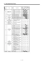
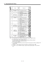
F5
Simple cam
function - Cam data
miswriting warning
F5.1
Cam data - Area writing time-out
warning
F5.2 Cam data - Area miswriting warning
F5.3 Cam data checksum error
F6
Simple cam
function - Cam
control warning
F6.1
Cam axis one cycle current value
restoration failed
F6.2
Cam axis feed current value
restoration failed
F6.3 Cam unregistered error
F6.4
Cam control data setting range
error
F6.5 Cam No. external error
F6.6 Cam control inactive
F7
Machine diagnosis
warning
F7.1 Vibration failure prediction warning
F7.2 Friction failure prediction warning
F7.3
Total travel distance failure
prediction warning
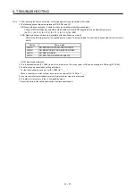
Note 1. After resolving the source of trouble, cool the equipment for approximately 30 minutes.
2. The following shows two stop methods of DB and SD.
DB: Stops with dynamic brake. (Coasts for the servo amplifier without dynamic brake.)
Coasts for MR-J4-03A6(-RJ) and MR-J4W2-0303B6.
SD: Forced stop deceleration
3. This is applicable when [Pr. PA04] is set to the initial value. The stop system of SD can be changed to DB
using [Pr. PA04].
4. For MR-J4-_A_ servo amplifier, quick stop or slow stop can be selected using [Pr. PD30].
5. For MR-J4-_GF_ servo amplifier, quick stop or slow stop can be selected using [Pr. PD12]. (I/O mode
only)
Summary of Contents for MR-J4-100B(-RJ)
Page 17: ...8 MEMO ...
Page 143: ...4 STARTUP 4 20 MEMO ...
Page 199: ...5 PARAMETERS 5 56 MEMO ...
Page 227: ...6 NORMAL GAIN ADJUSTMENT 6 28 MEMO ...
Page 281: ...8 TROUBLESHOOTING 8 16 MEMO ...
Page 303: ...9 DIMENSIONS 9 22 MEMO ...
Page 319: ...10 CHARACTERISTICS 10 16 MEMO ...
Page 429: ...11 OPTIONS AND PERIPHERAL EQUIPMENT 11 110 MEMO ...
Page 435: ...12 ABSOLUTE POSITION DETECTION SYSTEM 12 6 MEMO ...
Page 483: ...14 USING A LINEAR SERVO MOTOR 14 34 MEMO ...
Page 531: ...16 FULLY CLOSED LOOP SYSTEM 16 26 MEMO ...
Page 613: ...17 APPLICATION OF FUNCTIONS 17 82 MEMO ...
Page 654: ...APPENDIX App 41 ...