15. MR-J3W-0303BN6 SERVO AMPLIFIER
15 - 13
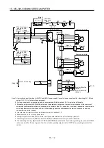
15.3.2 I/O signal connection example
23
10
CN3
19
(Note 12)
A-axis malfunction
(Note 11)
(Note 2)
Plate
LBR-B
2
MO1
1
LG
MO2
11
ALM-A
12
24
ALM-B
25
MBR-B
3
LA-A
16
LAR-A
4
LB-A
17
LBR-A
5
LA-B
18
LAR-B
Servo amplifier
(1 axis 2 axis)
26
B-axis malfunction
(Note11)
A-axis electromagnetic
brake interlock
CN3
(Note 12)
6
LB-B
A-axis encoder A-phase
pulse (Differential line driver)
A-axis encoder B-phase
pulse (Differential line driver)
B-axis encoder A-phase
pulse (Differential line driver)
B-axis encoder B-phase
pulse (Differential line driver)
Analog monitor 1
Analog monitor 2
(Note 13, 14)
24VDC
(Note 3, 4) Forced
A-axis upper stroke limit (FLS)
A-axis lower stroke limit (RLS)
A-axis proximity dog (DOG)
B-axis upper stroke limit (FLS)
B-axis lower stroke limit (RLS)
B-axis proximity dog (DOG)
(Note 15)
DICOM
EM1
DOCOM
7
DI1-A
8
DI2-A
9
DI3-A
CN1A
(Note 6)
SSCNET cable
(option)
Servo system
controller
CNP1
SW
2
1
SW (Note 8)
MR-J3W-B
(3 axis 4 axis)
(Note 6)
SSCNET cable
(option)
CN1A
CN1B
(Note 7)
(Note 1)
SW
2
1
SW (Note 8)
MR-J3W-B
(n-1 axis n axis)
(Note 9)
Cap
CN1A
CN1B
(Note 7)
SW
2
1
SW (Note 8)
LG
SD
15
14
(Note 5)
MR Configurator
Personal
computer
CN5
USB cable
MR-J3USBCBL3M
(option)
20
DI1-B
21
DI2-B
22
DI3-B
B-axis electromagnetic
brake interlock
MBR-A
RA1
RA2
RA3
RA4
(Note 10)
(Note 14)
10m or less
Output voltage: 10V 5V
Maximum current: 1mA
2m or less
10m or less
Summary of Contents for MELSERVO-J3W Series
Page 17: ...8 MEMO ...
Page 27: ...1 FUNCTIONS AND CONFIGURATION 1 10 MEMO ...
Page 87: ...4 STARTUP 4 14 MEMO ...
Page 117: ...5 PARAMETERS 5 30 MEMO ...
Page 129: ...6 GENERAL GAIN ADJUSTMENT 6 12 MEMO ...
Page 185: ...10 CHARACTERISTICS 10 8 MEMO ...
Page 241: ...11 OPTIONS AND AUXILIARY EQUIPMENT 11 56 MEMO ...
Page 274: ...13 USING A LINEAR SERVO MOTOR 13 25 1 2 3 4 ...


