15. MR-J3W-0303BN6 SERVO AMPLIFIER
15 - 23
15.3.6 Connection of servo amplifier and HG-AK series servo motor
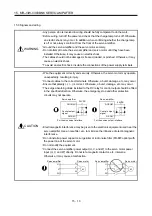
WARNING
Any person who is involved in wiring should be fully competent to do the work.
Ground the servo motor securely.
Do not attempt to wire the servo motor until it has been mounted. Otherwise, it may
cause an electric shock.
The cables should not be damaged, stressed, loaded, or pinched. Otherwise, it may
cause an electric shock.
To avoid an electric shock, insulate the connections of the power supply terminals.
CAUTION
Wire the equipment correctly and securely. Otherwise, the servo motor may operate
unexpectedly, resulting in injury.
Connect cables to the correct terminals. Otherwise, a burst, damage, etc. may occur.
Ensure that polarity ( / ) is correct. Otherwise, a burst, damage, etc. may occur.
Do not install a power capacitor, surge killer or radio noise filter (FR-BIF option) with
the power line of the servo motor.
Do not modify the equipment.
Connect the servo amplifier power output (U, V, and W) to the servo motor power
input (U, V, and W) directly. Do not let a magnetic contactor, etc. intervene.
Otherwise, it may cause a malfunction.
U
Servo motor
M
V
W
U
V
W
Servo motor
Servo amplifier
Servo amplifier
U
M
V
W
U
V
W
(1) Connection instructions
CAUTION
To avoid a malfunction, connect the wires to the correct phase terminals (U, V, and
W) of the servo amplifier and servo motor.
Do not connect AC power supply directly to the servo motor. Otherwise, it may cause
a malfunction.
Do not use a power supply for the electromagnetic brake with other 24VDC power
supplies. Always use the power supply designed exclusively for the electromagnetic
brake. Otherwise, it may cause a malfunction.
POINT
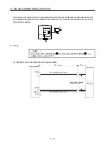
Refer to section 15.7.1 for selection of the encoder cable.
Refer to "Servo Motor Instruction Manual (Vol. 2)" for the selection of a surge
absorber for the electromagnetic brake.
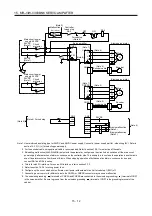
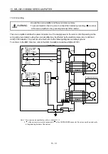
Connect the servo amplifier and servo motor by connecting an encoder cable and
servo motor power cable.
Summary of Contents for MELSERVO-J3W Series
Page 17: ...8 MEMO ...
Page 27: ...1 FUNCTIONS AND CONFIGURATION 1 10 MEMO ...
Page 87: ...4 STARTUP 4 14 MEMO ...
Page 117: ...5 PARAMETERS 5 30 MEMO ...
Page 129: ...6 GENERAL GAIN ADJUSTMENT 6 12 MEMO ...
Page 185: ...10 CHARACTERISTICS 10 8 MEMO ...
Page 241: ...11 OPTIONS AND AUXILIARY EQUIPMENT 11 56 MEMO ...
Page 274: ...13 USING A LINEAR SERVO MOTOR 13 25 1 2 3 4 ...


