14. USING A DIRECT DRIVE MOTOR
14 - 3
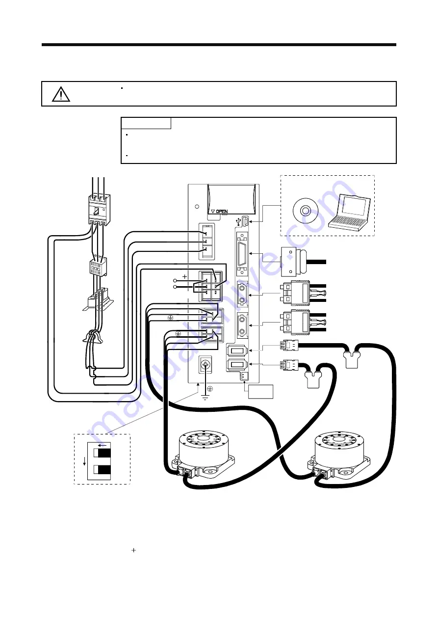
14.1.3 Configuration including peripheral equipment
CAUTION
Connecting a direct drive motor for different axis to the CNP3A or CNP3B connector
may cause a malfunction.
POINT
Equipment other than the servo amplifier and direct drive motor are optional or
recommended products.
When using the direct drive motor, turn on SW3.
(Note 3)
Absolute
position
storage unit
MR-BTAS01
Power factor
improving AC
reactor
Line noise
filter
(FR-BSF01)
(Note 2)
Power supply
Magnetic
contactor
(MC)
Molded-case
circuit breaker
(MCCB) or
fuse
CN5
P
L
21
L
11
U
V
Servo amplifier
(Note 1)
L
1
L
2
L
3
MR Configurator
Personal
computer
CN3
CN1A
CN1B
CN2A
CN2B
(Note 2)
R S T
CN4
W
W
V
U
CNP1
CNP2
CNP3A
CNP3B
I/O signal
2
1
NO
F
ront
side
SW3
A-axis
B-axis
(Note 3)
Absolute
position
storage unit
MR-BTAS01
A-axis direct
drive motor
(Note 4)
C
D
B-axis direct drive motor
Battery
unit
Regenerative
option
Servo system
controller or Front axis
servo amplifier CN1B
Rear servo amplifier
CN1A or Cap
Note 1. The battery unit consists of a battery case (MR-BTCASE) and 8 batteries (MR-BAT). The unit is used for the absolute position
detection system in the position control mode. (Refer to section 12.3.)
2. For 1-phase 200VAC to 230VAC, connect the power supply to L1 and L2. Leave L3 open. Refer to section 1.3 for the power supply
specification.
3. The absolute position storage unit is used for the absolute position detection system.
4. Always connect between P and D terminals. When using the regenerative option, refer to section 11.2.
Summary of Contents for MELSERVO-J3W Series
Page 17: ...8 MEMO ...
Page 27: ...1 FUNCTIONS AND CONFIGURATION 1 10 MEMO ...
Page 87: ...4 STARTUP 4 14 MEMO ...
Page 117: ...5 PARAMETERS 5 30 MEMO ...
Page 129: ...6 GENERAL GAIN ADJUSTMENT 6 12 MEMO ...
Page 185: ...10 CHARACTERISTICS 10 8 MEMO ...
Page 241: ...11 OPTIONS AND AUXILIARY EQUIPMENT 11 56 MEMO ...
Page 274: ...13 USING A LINEAR SERVO MOTOR 13 25 1 2 3 4 ...


