4. STARTUP
4 - 7
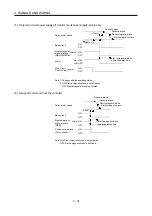
4.3.2 Status display of an axis
(1) Display sequence
Note.
Servo amplifier power ON
Servo system controller power ON
(SSCNET communication beginning)
Ready ON
Servo ON
Ordinary operation
Servo system controller power OFF
Servo system controller power ON
When alarm occurs,
alarm code appears.
Waiting for servo system controller
power to switch ON
(SSCNET communication)
(Note)
(Note)
(Note)
Example: At occurrence of overload
Example: At occurrence of overload
Flicker display
Flicker display
Flicker display
Flicker display
When alarm warning No. is displayed
Axis 1 Axis 2
Axis 16
Initial data communication with servo
system controller
(Initialization communication)
Ready OFF/servo OFF
After 2s
After 2s
Only alarm and warning No. are
displayed, but no axis No. is
displayed.
During a non servo-off causing
warning, the decimal point on the
third digit LED shows the servo-on
status.
Ready ON/servo OFF
Ready ON/servo ON
The segment of the last 2 digits shows the axis number.
(Below example indicates Axis 1)
Alarm reset or warning cleared
Summary of Contents for MELSERVO-J3W Series
Page 17: ...8 MEMO ...
Page 27: ...1 FUNCTIONS AND CONFIGURATION 1 10 MEMO ...
Page 87: ...4 STARTUP 4 14 MEMO ...
Page 117: ...5 PARAMETERS 5 30 MEMO ...
Page 129: ...6 GENERAL GAIN ADJUSTMENT 6 12 MEMO ...
Page 185: ...10 CHARACTERISTICS 10 8 MEMO ...
Page 241: ...11 OPTIONS AND AUXILIARY EQUIPMENT 11 56 MEMO ...
Page 274: ...13 USING A LINEAR SERVO MOTOR 13 25 1 2 3 4 ...


