14. USING A DIRECT DRIVE MOTOR
14 - 66
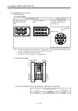
(2) Encoder connector set
(a) MR-J3DDCNS
This connector set is used to fabricate an encoder cable for the incremental system or the absolute
position detection system (between the servo amplifier and the absolute position storage unit).
Parts Description
Connector set
MR-J3DDCNS (option)
Servo amplifier-side connector
Receptacle: 36210-0100PL
Shell kit: 36310-3200-008
(3M)
or
Connector set: 54599-1019
(Molex)
Encoder side or absolute position storage
unit (connect from servo amplifier) side
connector
Plug: RM15WTPZK-12S
Cord clamp: JR13WCCA-8(72)
(Hirose Electric)
Applicable wire size: 0.25mm
2
(AWG 23) to 0.5mm
2
(AWG20)
(b) MR-J3DDSPS
This connector set is used to fabricate an encoder cable for the absolute position detection system
(between the absolute position storage unit and the direct drive motor).
Parts Description
Connector set
MR-J3DDSPS (option)
Absolute position storage unit-side
connector
Plug: RM15WTPZ-12P(72)
Cord clamp: JR13WCCA-8(72)
(Hirose Electric)
Encoder side connector
Plug: RM15WTPZK-12S
Cord clamp: JR13WCCA-8(72)
(Hirose Electric)
Applicable wire size: 0.25mm
2
(AWG 23) to 0.5mm
2
(AWG20)
(3) Fabricating encoder cables
POINT
The encoder cables should be fabricated by the customer. When fabricating the
cable, prepare the following parts (a) or (b), and fabricate it according to the wiring
diagram in (c).
Fabricate the encoder cable to be 50m or shorter between the servo amplifier and
the direct drive motor.
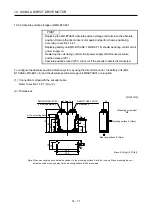
To configure the absolute position detection system by using the direct drive motor,
the battery unit (MR-BTCASE MR-BAT 8) and the absolute position storage unit
MR-BTAS01 are required.
For the absolute position detection system, refer to chapter 12.
Replacing battery unit (MR-BTCASE MR-BAT 8) should be during control circuit
power supply on.
Replacing the unit during control circuit power supply off will cause Absolute
position erased alarm (25.1).
Summary of Contents for MELSERVO-J3W Series
Page 17: ...8 MEMO ...
Page 27: ...1 FUNCTIONS AND CONFIGURATION 1 10 MEMO ...
Page 87: ...4 STARTUP 4 14 MEMO ...
Page 117: ...5 PARAMETERS 5 30 MEMO ...
Page 129: ...6 GENERAL GAIN ADJUSTMENT 6 12 MEMO ...
Page 185: ...10 CHARACTERISTICS 10 8 MEMO ...
Page 241: ...11 OPTIONS AND AUXILIARY EQUIPMENT 11 56 MEMO ...
Page 274: ...13 USING A LINEAR SERVO MOTOR 13 25 1 2 3 4 ...


