13. USING A LINEAR SERVO MOTOR
13 - 18
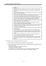
POINT
Establish the machine configuration using the stroke limits (FLS and RLS). If the
stroke limits (FLS and RLS) do not exist, it may cause the machine damage by a
collision.
At the magnetic pole detection, it is not predictable whether it moves to the positive
direction or the negative direction.
Setting the parameter No.PS09 (Magnetic pole detection voltage level) may cause
the occurrence of overload, overcurrent, magnetic pole detection alarm, etc.
When performing the positioning operation from the positioning controller, set the
sequence which confirms the normal completion of magnetic pole detection and
the servo-on status, then outputs the positioning command. If outputting the
positioning command before the Ready (RD-A/RD-B) turns ON, the command may
not be accepted or the servo alarm may occur.
After the magnetic pole detection, check the accuracy of position with the test
operation (positioning operation) of MR Configurator.
If a gap is generated to the positional relationship between the linear encoder and
the linear servo motor when using the absolute position linear encoder, carry out
the magnetic pole detection again.
The accuracy of magnetic pole detection will be improved by being operated in the
no-load condition.
The servo alarm may occur when the linear encoder is not mounted properly or
when the setting (parameter Nos. PS02 and PS03) of linear encoder resolution or
the setting value of parameter No.PS09 (magnetic detection voltage level) is not
correct.
On the machine of which friction becomes 30 or more than the rated thrust, it
may not operate properly after the magnetic pole detection.
On the machine of which imbalance thrust becomes 20 or more than the rated
thrust at the horizontal axis, it may not operate properly after the magnetic pole
detection.
For the following cases, the magnetic pole detection is required.
1) When using the incremental linear encoder (Refer to (2) (a) in this section)
2) When using the absolute position linear encoder and matching with the cases indicated below (Refer
to (2) (b) in this section)
At the system setup (at the first startup of equipment)
When the servo amplifier is replaced
When the linear servo motor (primary side (coil) or secondary side (magnet)) is replaced
When the linear encoder (scale or head) is replaced or its installation is changed
Summary of Contents for MELSERVO-J3W Series
Page 17: ...8 MEMO ...
Page 27: ...1 FUNCTIONS AND CONFIGURATION 1 10 MEMO ...
Page 87: ...4 STARTUP 4 14 MEMO ...
Page 117: ...5 PARAMETERS 5 30 MEMO ...
Page 129: ...6 GENERAL GAIN ADJUSTMENT 6 12 MEMO ...
Page 185: ...10 CHARACTERISTICS 10 8 MEMO ...
Page 241: ...11 OPTIONS AND AUXILIARY EQUIPMENT 11 56 MEMO ...
Page 274: ...13 USING A LINEAR SERVO MOTOR 13 25 1 2 3 4 ...


