8. TROUBLESHOOTING
8 - 33
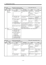
Warning No. E7
Name: Controller forced stop warning
Stop method: All axes stop
Warning description
Forced stop signal is input from the servo system controller.
Display Name
Cause
Checkpoint
Finding
Action
E7.1 Controller
forced
stop warning
(1) Forced stop signal was
input from the servo
system controller.
Check if the servo system
controller is in forced stop
status.
In forced stop status.
Ensure safety and
deactivate forced stop
signal of the controller.
Warning No. E8
Name: Cooling fan speed reduction warning
Stop method: Axes can operate (warning
detected at both axes)
Warning description
The speed of cooling fan drops to or below the warning level.
Display Name
Cause
Checkpoint
Finding
Action
E8.1 (1)
Check for foreign matter
adhesion.
Adhered.
Remove the foreign
matter.
Decreased
cooling fan speed
warning
Foreign matter is caught
in the fan causing
decreased speed.
Not adhered.
Check (2).
(2) Cooling fan life expiration. Check the cumulative
power supply time of the
servo amplifier.
Life is expired.
Replace the servo
amplifier, or repair
(replace) the cooling
fan.
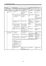
Warning No. E9
Name: Main circuit off warning
Stop method: All axes stop (warning detected
at both axes).
Warning description
Servo-on command is input when the main circuit power is off.
Bus voltage drops when servo motor is running below 50r/min.
Display Name
Cause
Checkpoint
Finding
Action
E9.1
(1) Main circuit power is off.
Check the main circuit
power input.
Not input.
Turn on the main
circuit power.
Ready-on signal
on at main circuit
off
Input.
Check
(2).
(2)
Disconnected.
Connect
properly.
Connector for the main
circuit power is
disconnected.
Check the connector of
the main circuit power.
No problem found.
Check (3).
(3) Bus voltage is below
215VDC.
Check the bus voltage
value with MR
Configurator.
Below 215VDC.
Review the wiring.
Review the power
supply capacity.
E9.2
Bus voltage drop
during low speed
operation
(1) Bus voltage drops when
motor is running below
50[r/min].
Check the bus voltage
value at the monitor.
Below 200VDC.
Review the power
supply capacity.
Set acceleration time
longer.
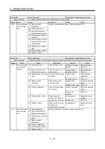
E9.3
(1) Main circuit power is off.
Examine checkpoints described in the alarm display "E9.1".
(2) Connector for the main
circuit power is
disconnected.
Servo-on signal
on at main circuit
off
(3) Bus voltage is below
215VDC.
Summary of Contents for MELSERVO-J3W Series
Page 17: ...8 MEMO ...
Page 27: ...1 FUNCTIONS AND CONFIGURATION 1 10 MEMO ...
Page 87: ...4 STARTUP 4 14 MEMO ...
Page 117: ...5 PARAMETERS 5 30 MEMO ...
Page 129: ...6 GENERAL GAIN ADJUSTMENT 6 12 MEMO ...
Page 185: ...10 CHARACTERISTICS 10 8 MEMO ...
Page 241: ...11 OPTIONS AND AUXILIARY EQUIPMENT 11 56 MEMO ...
Page 274: ...13 USING A LINEAR SERVO MOTOR 13 25 1 2 3 4 ...


