14. USING A DIRECT DRIVE MOTOR
14 - 11
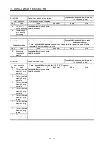
Note 1. Signal can be assigned for these pins with the controller setting. For contents of signals, refer to the instruction manual of the
controller.
2. This is for sink I/O interface. For source I/O interface, refer to section 3.7.3.
3. When you using a direct drive motor, use MBR (Electromagnetic brake interlock) for an external brake mechanism.
4. The encoder detects speed, position, and temperature of the direct drive motor.
5. The encoder cable should be fabricated by the customer. (Refer to section 14.8.1.)
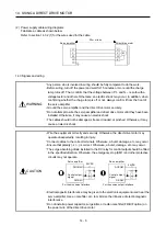
6. The connection is for incremental system. For the connection for the absolute position detection system, refer to the following
diagram.
3
2
4
MR
MRR
LG
CN2A
5 THM1
6 THM2
1
P5
9
BAT
MR
MRR
LG
THM1
7
10
8
6
11
THM2
MR
MRR
LG
THM1
THM2
7
10
8
6
11
2
P5
9
BAT
2
9
1
BAT
P5
VB
E
M
MR
MRR
LG
THM1
THM2
7
10
8
6
11
2
9
1
BAT
P5
VB
Encoder
P5
CNP3A
2A
3
2
4
MR
MRR
LG
CN2B
5 THM1
6 THM2
1
P5
9
BAT
MR
MRR
LG
THM1
7
10
8
6
11
THM2
MR
MRR
LG
THM1
THM2
7
10
8
6
11
2
P5
9
BAT
2
9
1
BAT
P5
VB
E
M
MR
MRR
LG
THM1
THM2
7
10
8
6
11
2
9
1
BAT
P5
VB
B-axis direct
drive motor
Encoder
CNP3B
2A
P5
A-axis direct
drive motor
Absolute position
storage unit
MR-BTAS01
Absolute position
storage unit
MR-BTAS01
14.4 Operation and functions
POINT
When using a linear servo motor, turn on SW3.
SW3
1
ON
2
F
ront
s
id
e
Summary of Contents for MELSERVO-J3W Series
Page 17: ...8 MEMO ...
Page 27: ...1 FUNCTIONS AND CONFIGURATION 1 10 MEMO ...
Page 87: ...4 STARTUP 4 14 MEMO ...
Page 117: ...5 PARAMETERS 5 30 MEMO ...
Page 129: ...6 GENERAL GAIN ADJUSTMENT 6 12 MEMO ...
Page 185: ...10 CHARACTERISTICS 10 8 MEMO ...
Page 241: ...11 OPTIONS AND AUXILIARY EQUIPMENT 11 56 MEMO ...
Page 274: ...13 USING A LINEAR SERVO MOTOR 13 25 1 2 3 4 ...

