3. SIGNALS AND WIRING
3 - 19
3.7 Interfaces
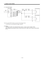
3.7.1 Internal connection diagram
MO2
LG
15
1
Encoder
B-axis servo motor
D
Analog monitor
Encoder
Differential line
driver output
(35mA or less)
A-axis servo motor
Approx
5.6k
EM1
CN3
DICOM
23
CN3
Servo amplifier
(Note 1)
GND
VBUS
D
1
2
3
5
CN5
DOCOM
24VDC
(Note 2)
DI1-A
DI2-A
DI3-A
DI1-B
DI2-B
DI3-B
26
10
7
8
9
20
21
22
11
12
24
25
ALM-A
MBR-A
ALM-B
MBR-B
(Note 2)
RA
RA
CN3
MO1
2
CN3
3
16
4
17
5
18
LA-A
3
2
4
7
8
MR
MRR
MD
MDR
LG
E
M
CN2A
6
19
LAR-A
LB-A
LBR-A
LA-B
LAR-B
LB-B
LBR-B
CNP3A
2A
3
2
4
7
8
MR
MRR
MD
MDR
LG
E
M
CN2B
CNP3B
2A
Approx
5.6k
<Isolated>
10VDC
10VDC
USB
14
LG
Note 1. Signal can be assigned for these pins with the controller setting.
For contents of signals, refer to the instruction manual of the controller.
2. For the sink I/O interface. For the source I/O interface, refer to section 3.7.3.
Summary of Contents for MELSERVO-J3W Series
Page 17: ...8 MEMO ...
Page 27: ...1 FUNCTIONS AND CONFIGURATION 1 10 MEMO ...
Page 87: ...4 STARTUP 4 14 MEMO ...
Page 117: ...5 PARAMETERS 5 30 MEMO ...
Page 129: ...6 GENERAL GAIN ADJUSTMENT 6 12 MEMO ...
Page 185: ...10 CHARACTERISTICS 10 8 MEMO ...
Page 241: ...11 OPTIONS AND AUXILIARY EQUIPMENT 11 56 MEMO ...
Page 274: ...13 USING A LINEAR SERVO MOTOR 13 25 1 2 3 4 ...


