11. OPTIONS AND AUXILIARY EQUIPMENT
11 - 19
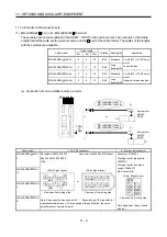
(c) When fabricating the encoder cable
When fabricating the cable, prepare the following parts and tool, and fabricate it according to the wiring
diagram in (b). Refer to section 11.5 for the specifications of the used cable.
Parts/Tool
(Connector set)
Description
MR-J3SCNS
(Note 2)
Encoder side connector
Straight plug: CMV1-SP10S-M2
Socket contact: CMV1-#22ASC-S1-100
Applicable wire size: AWG20 or less
(DDK)
MR-J3SCNS-S06
(Note 1)
Servo amplifier side connector
Receptacle: 36210-0100PL
Shell kit: 536310-3200-008
(3M)
Or
Connector set: 54599-1019
(Molex)
Encoder side connector
Straight plug: CM10-SP10S-VP-M
Socket contact: CM10-#22SC (S1) (D8)-100
Applicable wire size: AWG20 or less
(DDK)
MR-J3SCNSA
(Note 2)
Encoder side connector
Straight plug: CMV1-AP10S-M2
Socket contact: CMV1-#22ASC-S1-100
Applicable wire size: AWG20 or less
(DDK)
MR-J3SCNSA-S06
(Note 1)
Encoder side connector
Straight plug: CM10-AP10S-VP-M
Socket contact: CM10-#22SC (S1) (D8)-100
Applicable wire size: AWG20 or less
(DDK)
Note 1. Use this option when the connector is expected to receive large vibration and shock. The connector at the
servo motor side can be removed up to 5 times. Use the dedicated tool 357J-52780T (DDK) or a spanner with
jaw size of 21mm.
2. Cable clamp and bushing for 5.5 mm to 7.5 mm and 7.0 mm to 9.0 mm of cable outer diameter are included.
Summary of Contents for MELSERVO-J3W Series
Page 17: ...8 MEMO ...
Page 27: ...1 FUNCTIONS AND CONFIGURATION 1 10 MEMO ...
Page 87: ...4 STARTUP 4 14 MEMO ...
Page 117: ...5 PARAMETERS 5 30 MEMO ...
Page 129: ...6 GENERAL GAIN ADJUSTMENT 6 12 MEMO ...
Page 185: ...10 CHARACTERISTICS 10 8 MEMO ...
Page 241: ...11 OPTIONS AND AUXILIARY EQUIPMENT 11 56 MEMO ...
Page 274: ...13 USING A LINEAR SERVO MOTOR 13 25 1 2 3 4 ...


