3. SIGNALS AND WIRING
3 - 21
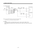
(3) Encoder output pulse DO-2 (differential line driver type)
(a) Interface
Max. output current: 35mA
LA-A/LA-B
(LB-A/LB-B)
LAR-A/LAR-B
(LBR-A/LBR-B)
LA-A/LA-B
(LB-A/LB-B)
LAR-A/LAR-B
(LBR-A/LBR-B)
Servo amplifier
SD
LG
150
Am26LS32 or equivalent
High-speed photocoupler
Servo amplifier
SD
100
(b) Output pulse
T
/2
Servo motor CCW rotation
LBR-A/LBR-B
LB-A/LB-B
LAR-A/LAR-B
LA-A/LA-B
Time cycle (T) is determined by the settings
of parameter No.PA15, PA16 and PC03.
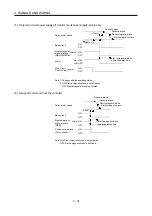
(4) Analog output
LG
MO1
(MO2)
Servo amplifier
Output voltage: 10V (Note)
Max. Output current: 1mA
Resolution: 10 bits or equivalent
Note. Output voltage range varies depending on the monitored signal. (Refer to section 5.3.3
or 13.8.4(3).) When connecting an analog output to an external device, use one whose
withstand voltage is 15VDC or more.
Summary of Contents for MELSERVO-J3W Series
Page 17: ...8 MEMO ...
Page 27: ...1 FUNCTIONS AND CONFIGURATION 1 10 MEMO ...
Page 87: ...4 STARTUP 4 14 MEMO ...
Page 117: ...5 PARAMETERS 5 30 MEMO ...
Page 129: ...6 GENERAL GAIN ADJUSTMENT 6 12 MEMO ...
Page 185: ...10 CHARACTERISTICS 10 8 MEMO ...
Page 241: ...11 OPTIONS AND AUXILIARY EQUIPMENT 11 56 MEMO ...
Page 274: ...13 USING A LINEAR SERVO MOTOR 13 25 1 2 3 4 ...


