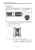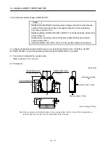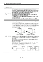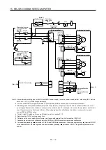
15. MR-J3W-0303BN6 SERVO AMPLIFIER
15 - 8
15.2 Installation (direction and clearances)
WARNING
To prevent electric shock, ground each equipment securely.
CAUTION
Stacking in excess of the specified number of product packages is not allowed.
Install the equipment on incombustible material. Installing it directly or close to
combustibles will lead to a fire.
Install the equipment in a load-bearing place in accordance with the Instruction
Manual.
Do not get on or put heavy load on the equipment. Otherwise, it may cause injury.
Use the equipment within the specified environment. (For the environment, refer to
section 1.3.)
Provide an adequate protection to prevent screws and other conductive matter, oil
and other combustible matter from entering the servo amplifier.
Do not block the intake and exhaust areas of the servo amplifier. Otherwise, it may
cause a malfunction.
Do not drop or strike the servo amplifier. Isolate it from all impact loads.
Do not install or operate a faulty servo amplifier.
When the product has been stored for an extended period of time, contact your local
sales office.
When handling the servo amplifier, be careful about the edged parts such as corners
of the servo amplifier.
The servo amplifier must be installed in a metal cabinet.
The equipment must be installed in the specified direction. Otherwise, it may cause a
malfunction.
Leave specified clearances between the servo amplifier and the cabinet walls or
other equipment. Otherwise, it may cause a malfunction.
POINT
This section does not include the following items. For details of the items, refer to
each section of the detailed description field.
Item
Detailed
explanation
Summary Section
1.1
Function list
Section 1.4
When using heat generating equipment, install them with full consideration of heat generation so that the servo
amplifier is not affected.
Install the servo amplifier on a perpendicular wall in the correct vertical direction.
Summary of Contents for MELSERVO-J3W Series
Page 17: ...8 MEMO ...
Page 27: ...1 FUNCTIONS AND CONFIGURATION 1 10 MEMO ...
Page 87: ...4 STARTUP 4 14 MEMO ...
Page 117: ...5 PARAMETERS 5 30 MEMO ...
Page 129: ...6 GENERAL GAIN ADJUSTMENT 6 12 MEMO ...
Page 185: ...10 CHARACTERISTICS 10 8 MEMO ...
Page 241: ...11 OPTIONS AND AUXILIARY EQUIPMENT 11 56 MEMO ...
Page 274: ...13 USING A LINEAR SERVO MOTOR 13 25 1 2 3 4 ...


