11. OPTIONS AND AUXILIARY EQUIPMENT
11 - 21
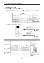
11.1.4 Motor brake cables
These cables are motor brake cables for the HF-MP HF-KP series servo motors. The numerals in the Cable
length field of the table are the symbols entered in the part of the cable model. The cables of the lengths with
the symbols are available.
Refer to section 3.11 when wiring.
Cable
length
Cable model
0.3m 2m 5m 10m
IP rating Bending life
Application
MR-PWS1CBL M-A1-L 2 5 10 IP65
Standard
For HF-MP HF-KP servo motor
Load side lead
MR-PWS1CBL M-A2-L 2 5 10 IP65
Standard
For HF-MP HF-KP servo motor
Opposite-to-load side lead
MR-PWS1CBL M-A1-H 2 5 10 IP65
Long
bending life
For HF-MP HF-KP servo motor
Load side lead
MR-PWS1CBL M-A2-H 2 5 10 IP65
Long
bending life
For HF-MP HF-KP servo motor
Opposite-to-load side lead
MR-PWS2CBL03M-A1-L 03
IP55 Standard For HF-MP HF-KP servo motor
Load side lead
MR-PWS2CBL03M-A2-L 03
IP55 Standard For HF-MP HF-KP servo motor
Opposite-to-load side lead
(1) Connection of power supply for electromagnetic brake and servo motor
1)
Servo motor
HF-MP
HF-KP
24VDC power
supply for
electromagnetic
brake
MR-BKS1CBL M-A2-L
MR-BKS1CBL M-A2-H
MR-BKS2CBL03M-A2-L
1)
Servo motor
HF-MP
HF-KP
MR-BKS1CBL M-A1-L
MR-BKS1CBL M-A1-H
MR-BKS2CBL03M-A1-L
or
Cable model
1) For motor brake connector
MR-BKS1CBL M-A1-L
MR-BKS1CBL M-A2-L
MR-BKS1CBL M-A1-H
MR-BKS1CBL M-A2-H
Connector: JN4FT02SJ1-R
Hood, socket insulator
Bushing, ground nut
Contact: ST-TMH-S-C1B-100-(A534G)
Crimping tool: CT160-3-TMH5B
(Japan Aviation Electronics Industry)
MR-BKS2CBL03M-A1-L
MR-BKS2CBL03M-A2-L
Connector: JN4FT02SJ2-R
Hood, socket insulator
Bushing, ground nut
Contact: ST-TMH-S-C1B-100-(A534G)
Crimping tool: CT160-3-TMH5B
(Japan Aviation Electronics Industry)
B1
B2
1
2
View seen from wiring side.
Signal layout
(2) Internal wiring diagram
AWG 20
AWG 20
B1
B2
MR-BKS1CBL M-A1-L MR-BKS1CBL M-A2-L
MR-BKS1CBL M-A1-H MR-BKS1CBL M-A2-H
MR-BKS2CBL03M-A1-L MR-BKS2CBL03M-A2-L
(Note)
Note. These are not shielded cables.
Summary of Contents for MELSERVO-J3W Series
Page 17: ...8 MEMO ...
Page 27: ...1 FUNCTIONS AND CONFIGURATION 1 10 MEMO ...
Page 87: ...4 STARTUP 4 14 MEMO ...
Page 117: ...5 PARAMETERS 5 30 MEMO ...
Page 129: ...6 GENERAL GAIN ADJUSTMENT 6 12 MEMO ...
Page 185: ...10 CHARACTERISTICS 10 8 MEMO ...
Page 241: ...11 OPTIONS AND AUXILIARY EQUIPMENT 11 56 MEMO ...
Page 274: ...13 USING A LINEAR SERVO MOTOR 13 25 1 2 3 4 ...


