15. MR-J3W-0303BN6 SERVO AMPLIFIER
15 - 31
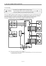
15.3.8 Grounding
WARNING
Ground the servo amplifier and the servo motor securely.
To prevent electric shock, be sure to connect the noiseless grounding (
) terminal
of the servo amplifier to the grounding terminal of the cabinet.
The servo amplifier switches the power transistor on-off to supply power to the servo motor. Depending on the
wiring and ground cable routing, the servo amplifier may be affected by the switching noise (due to di/dt and
dv/dt) of the transistor. To prevent such a fault, refer to the following diagram and always ground.
To conform to the EMC Directive, refer to the EMC Installation Guidelines (IB(NA)67310).
W
V
U
Control box
A-axis servo motor
M
U
V
W
CN2A
Servo amplifier
CNP2A
Grounding terminal
Outer
box
24
0
PM
CNP1
(Note 2)
Encoder
W
V
U
B-axis servo motor
M
U
V
W
CN2B
CNP2B
Encoder
Circuit
protector
24VDC
(Note 1)
48VDC
(Note 1)
Main circuit power
supply: 48VDC
Circuit
protector
24VDC
(Note 1)
Main circuit power
supply: 24VDC
Servo syst
em
cont
roller
RA
CNP1
(Note 2)
Note 1. For power supply specifications, refer to section 15.1.2.
2.
of the servo motor must be connected to
of the CNP2A/CNP2B connector. Do not connect the wire directly
to the grounding terminal of the cabinet.
Summary of Contents for MELSERVO-J3W Series
Page 17: ...8 MEMO ...
Page 27: ...1 FUNCTIONS AND CONFIGURATION 1 10 MEMO ...
Page 87: ...4 STARTUP 4 14 MEMO ...
Page 117: ...5 PARAMETERS 5 30 MEMO ...
Page 129: ...6 GENERAL GAIN ADJUSTMENT 6 12 MEMO ...
Page 185: ...10 CHARACTERISTICS 10 8 MEMO ...
Page 241: ...11 OPTIONS AND AUXILIARY EQUIPMENT 11 56 MEMO ...
Page 274: ...13 USING A LINEAR SERVO MOTOR 13 25 1 2 3 4 ...


