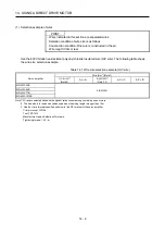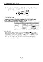
14. USING A DIRECT DRIVE MOTOR
14 - 22
(b) Sequence program example of servo parameters on the positioning module
POINT
For QD75MH , the parameter error (37. ) will occur if servo parameters are not
initialized.
The number of write time to the flash ROM is limited to 100,000. Therefore, try to
write to the flash ROM only when changing the servo parameter instead of writing
with every sequence program. When controlling multiple axes, write the servo
parameters to all axes.
1) Sequence program example when QD75MH is used.
The following shows the example of writing the axis No.1 servo parameter to the flash ROM.
After changing the servo parameter, turn on the power of QD75MH again or reset the CPU,
then send the setting value to the servo amplifier. Refer to (2) (c) of this section for the address of
the special setting parameters (No.PS ) of the servo parameters.
K30273 K0
K30274 K100
K30275 H0010
K30279 K500
K30284 H0000
K30285 H0000
K1900
K1
K30198 H0020
K30268 H0301
K30271 H0003
K30272 K0
K30100 K6
K30164 K0
K30166 H0010
TOP
H0
K1
TOP
H0
K1
TOP
H0
K1
TOP
H0
K1
TOP
H0
K1
TOP
H0
K1
TOP
H0
K1
(Note 1)
Write condition
Setting of the servo parameter No.PS06
Setting of the servo parameter No.PS07
Setting of the servo parameter No.PS08 (Note 2)
Setting of the servo parameter No.PS12
Setting of the servo parameter No.PS17
Setting of the servo parameter No.PS18
Write to flash ROM
TOP
H0
K1
TOP
H0
K1
TOP
H0
K1
TOP
H0
K1
Setting of the servo parameter No.PD03
Setting of the servo parameter No.PS01
Setting of the servo parameter No.PS04
Setting of the servo parameter No.PS05
TOP
H0
K1
TOP
H0
K1
TOP
H0
K1
Servo amplifier series
Setting of the servo parameter No.PC01
Setting of the servo parameter No.PC03
TOP
H0
K30199 H0021 K1
Setting of the servo parameter No.PD04
TOP
H0
K30276 K30
K1
TOP
H0
K30277 K5
K1
TOP
H0
K30278 K100
K1
Setting of the servo parameter No.PS09
Setting of the servo parameter No.PS10
Setting of the servo parameter No.PS11
K30101 H0060
TOP
H0
K1
Setting of the servo parameter No.PA01
Note 1. Configure a sequence program where the servo parameters are written to the flash ROM only when a servo parameter is changed.
2. Change the sequence program of the servo parameter No.PS08 to the following sequence program for the magnetic pole detection
without the stroke limit (FLS and RLS).
TOP
H0
K30275 K0110 K1
Setting of the servo parameter
No.PS08
However, do not change to this sequence program if using the stroke limit (FLS and RLS) at the QD75MH side.
Summary of Contents for MELSERVO-J3W Series
Page 17: ...8 MEMO ...
Page 27: ...1 FUNCTIONS AND CONFIGURATION 1 10 MEMO ...
Page 87: ...4 STARTUP 4 14 MEMO ...
Page 117: ...5 PARAMETERS 5 30 MEMO ...
Page 129: ...6 GENERAL GAIN ADJUSTMENT 6 12 MEMO ...
Page 185: ...10 CHARACTERISTICS 10 8 MEMO ...
Page 241: ...11 OPTIONS AND AUXILIARY EQUIPMENT 11 56 MEMO ...
Page 274: ...13 USING A LINEAR SERVO MOTOR 13 25 1 2 3 4 ...


