IAI Rcon Instruction Manual Download Page 3

ME0384-4A


RCON System Instruction Manual Configuration 
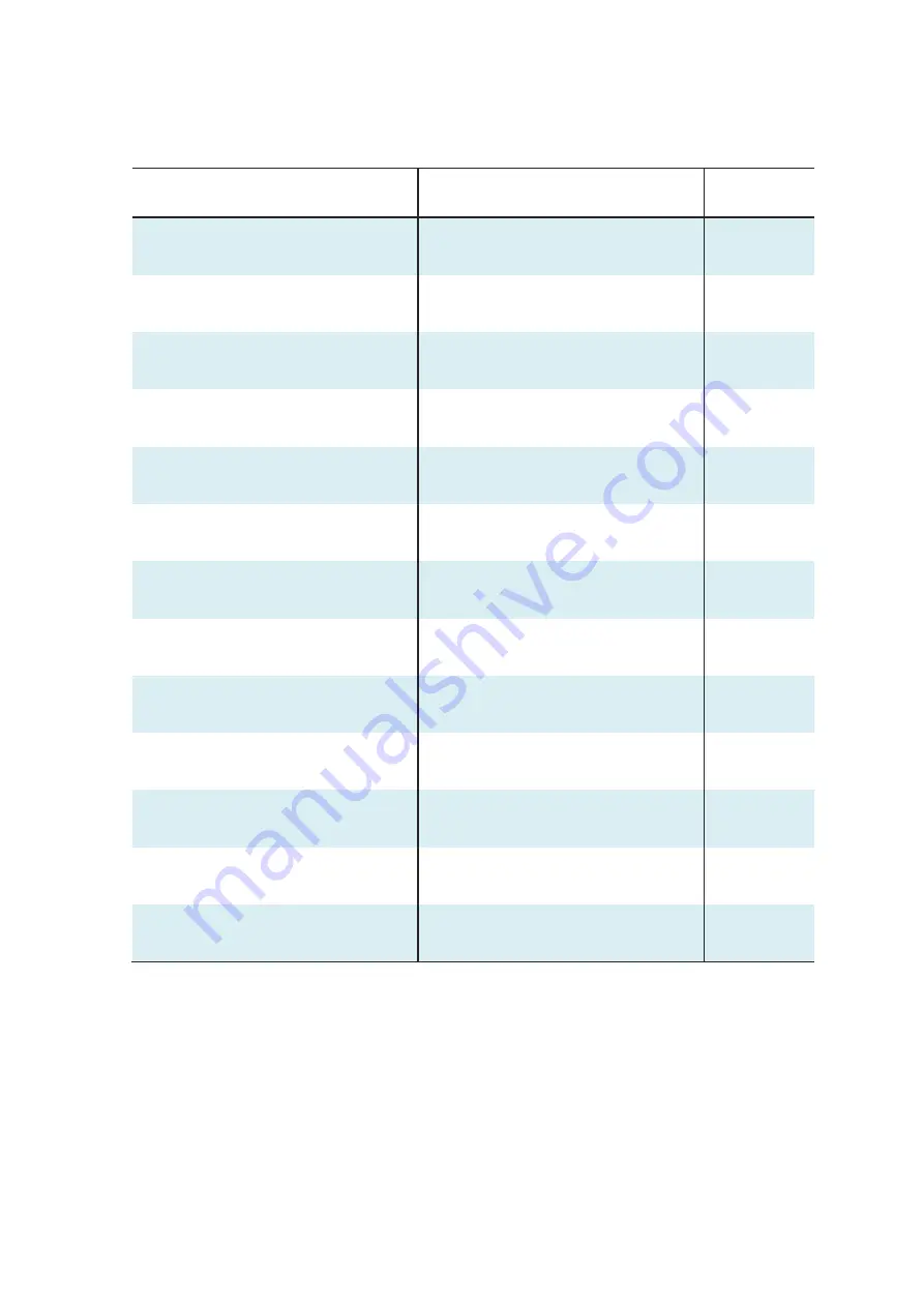
 

Product name 

Instruction manual name


Control 

number 

RCON Gateway Unit 

First Step Guide 

ME0382 

RCON 24V Driver Unit 

First Step Guide 

ME0383 

RCON 200V 

Power Supply / Driver Unit


First Step Guide


ME0397


REC

 System


First Step Guide


ME0395


RCON System


Instruction Manual (this document)


ME0384


REC

 System 

REC-GW/RCON-EC 

Instruction Manual 

ME0394


SCON-CB Controller 

SCON-CB/CGB/LC/LCG 

Instruction Manual 

ME0340 

PC Software


RCM-101-MW/RCM-101-USB 

Instruction Manual 

ME0155 

Touch Panel Teaching Pendant 

TB-02/02D Instruction Manual 

ME0355 

Touch Panel Teaching Pendant 

TB-03 Instruction Manual 

ME0376 

24V Power Supply Unit 

PSA-24 Instruction Manual 

ME0379 

Calculator


Calculator Instruction Manual


ME0381


Network Startup Guide


Quick Start Guide 

Download from IAI 

homepage


Summary of Contents for Rcon

Page 1: ...on Unit Chapter 7 Simple Absolute Unit Specifications Section Chapter 1 Maintenance and Inspection Chapter 2 Troubleshooting Maintenance Section Chapter 1 Conforming to Safety Category Chapter 2 Connectable Actuators Appendix Chapter 1 Overview Chapter 2 Mounting and Wiring Chapter 3 Absolute Reset Chapter 4 Network Configuration Chapter 5 BasicOperationConfirmationandAdjustment Chapter 6 Paramete...

Page 2: ... place so that whoever is handling the product can refer to it quickly when necessary Important This instruction manual is an original document dedicated for this product This product cannot be used in ways not shown in this instruction manual IAI shall not be liable for any result whatsoever arising from the use of the product in any other way than what is noted in the manual The information cont...

Page 3: ...uction Manual this document ME0384 REC System REC GW RCON EC Instruction Manual ME0394 SCON CB Controller SCON CB CGB LC LCG Instruction Manual ME0340 PC Software RCM 101 MW RCM 101 USB Instruction Manual ME0155 Touch Panel Teaching Pendant TB 02 02D Instruction Manual ME0355 Touch Panel Teaching Pendant TB 03 Instruction Manual ME0376 24V Power Supply Unit PSA 24 Instruction Manual ME0379 Calcula...

Page 4: ...eneral specifications A2 7 Power supply capacity A2 10 Power ON sequence A2 16 Inrush current A2 18 Operating temperature range A2 20 Installation conditions A2 21 Unit connection restrictions A2 25 2 4 External Dimensions A2 27 Controller 24V Driver Unit 8 axis without fan A2 27 Controller 24V Driver Unit 8 axis with fan A2 28 Controller 24V Driver Unit 16 axis without fan A2 29 Controller 24V Dr...

Page 5: ...3 45 Position table A3 48 Direct numerical control mode assignment A3 64 Simple direct mode assignment A3 70 Positioner 1 mode assignment A3 74 Positioner 2 mode assignment A3 77 Positioner 3 mode assignment A3 78 Positioner 5 mode assignment A3 81 ELECYLINDER Position Table A3 84 Assignment of EC Connection Unit A3 87 3 8 I O Signals A3 90 Timing of I O signals A3 90 Function of I O signals A3 91...

Page 6: ...ernal dimensions 24V Driever unit Fun unit A4 19 EC Connection Unit Part names A4 21 LED display A4 22 Brake release switch A4 24 onnectors for EC Connection A4 25 Drive source shutoff connector A4 26 Connectors A4 27 External dimensions A4 28 Chapter 5 200V Driver Unit 200V Power Supply Unit 5 1 Overview A5 1 5 2 How to Read the Model Number A5 3 How to read the model nameplate A5 4 5 3 Component...

Page 7: ... Model Number A7 3 How to read the model nameplate A7 4 7 3 Simple Absolute Unit and Components A7 5 7 4 General Specifications A7 6 7 5 Part Names Functions and External Dimensions A7 10 Part names A7 10 LED display A7 11 Actuator cable connector driver unit cable connector A7 11 External dimensions A7 12 7 6 Precautions A7 13 Startup Section Chapter 1 Overview 1 1 Checking the Product B1 1 1 2 T...

Page 8: ...nstalling PC software B4 42 Installing B4 42 4 4 Address Configuration B4 46 Overall address configuration example B4 48 Gateway control status signals B4 59 Power supply unit PSA 24 status signal B4 61 Chapter 5 Basic Operation Confirmation and Adjust ment 5 1 Operation Confirmation with PC Software B5 1 Home return B5 10 Jog travel B5 12 Position travel B5 13 Operation Check of ELECYLINDER B5 16...

Page 9: ... C2 5 Causes and countermeasures of individual alarms C2 5 2 4 Driver Unit Simple Absolute Unit Alarm Causes and Countermeasures C2 9 Alarm levels C2 9 Simple alarm codes C2 10 Causes and countermeasures of individual alarms C2 12 2 5 Causes and countermeasures for ELECYLINDER alarms C2 29 ELECYLINDER Alarm Group C2 29 Troubleshooting for ELECYLINDER alarm groups C2 30 Appendix Chapter 1 Conformin...

Page 10: ...High output effective Motor reversing type D2 117 RCP6 table type High output effective D2 119 RCP6 table type High output effective Motor reversing type D2 120 RCP6 table type High output effective D2 121 RCP6 table type High output effective Motor reversing type D2 122 RCP5 slider type High output effective D2 123 RCP5 slider type High output effective Motor reversing type D2 124 RCP5 belt type ...

Page 11: ...Slim compact rod type RA2AC RA2BC RA2AR RA2BR D2 158 RCP2 Series Slider type Rod type D2 158 RCP2 Series 2 finger gripper type D2 160 RCP2 Series 3 finger gripper type D2 161 RCL Series D2 161 RCD Series D2 161 RCS2 Series D2 162 2 4 Rotational speed and Output torque Allowable inertial moment D2 163 RCP2 Series Rotary type D2 163 2 5 List of Actuators That Support Information Management Function ...

Page 12: ...ME0384 4A ...

Page 13: ...ents essential for safety safety devices etc Do not use the product outside the range of the specifications Otherwise the product life may be drastically shortened and product damage or facilities stoppage may occur Do not use it in any of the following environments 1 Locations with flammable gases ignitable objects or explosives 2 Locations with potential exposure to radiation 3 Locations with am...

Page 14: ...is free of damage Do not climb on loads suspended from cranes Do not leave loads suspended from cranes for long periods Do not stand under loads suspended from cranes 3 Storage and Preservation For the storage and preservation environment see the installation environment However give especial consideration to the prevention of condensation Store the products so as to prevent them from falling over...

Page 15: ...ead to fire electric shock or abnormal operation of the product Never cut or reconnect the cables supplied with the product for the purpose of extending or shortening the cable length Otherwise this may lead to fire or abnormal operation of the product 3 Grounding Grounding must be performed in order to prevent electric shocks or electrostatic charge enhance noise resistant performance and control...

Page 16: ...Do not insert fingers or objects into the openings in the product Otherwise this may lead to injury electric shock product damage or fire When releasing the brake on a vertically oriented actuator be careful that it does not fall under its own weight catching the operator s hand or damaging workpieces 5 Teaching When working with two or more persons make it clear who is to be in charge and communi...

Page 17: ... the various setting switches while the equipment is live Otherwise this may lead to electric shock or abnormal operation 7 Automatic Operation Check before starting automatic operation or restarting after operation stop that there is nobody within the safety protection fence Before starting automatic operation make sure that all peripheral equipment is ready for automatic operation and that there...

Page 18: ... may lead to damage to the product When releasing the brake on a vertically oriented actuator be careful that it does not fall under its own weight catching the operator s hand or damaging workpieces The slider or rod may be misaligned from the stop position if the servo is turned OFF Avoid injury or damage due to unnecessary operation Be careful not to lose the cover or any removed screws and be ...

Page 19: ...roduct is not handled correctly will result in death or serious injury Danger Warning This indicates a potentially hazardous situation which if the product is not handled correctly could result in death or serious injury Warning Caution This indicates a potentially hazardous situation which if the product is not handled correctly may result in minor injury or property damage Caution Notice This in...

Page 20: ...power is turned off However be sure to save the latest data to enable a quick recovery process in case this controller needs to be replaced with a substitute due to breakdown etc How to save 1 Save to an external memory or a hard disk using PC software 2 Record position table and parameters in writing 4 Perform initial operation setting This controller is compatible with 7 types of field network t...

Page 21: ... take measures against wear due to rubbing or wire disconnection due to twisting Be particularly cautious if the actuator is 360 degree specification as it can infinitely rotate in the same direction 8 There are restrictions on index mode operation of the rotary actuator With use of Parameter No 79 Rotary Axis Mode Select rotary actuators with 360 degree specification allow selection of normal mod...

Page 22: ...e sure the safety factor of the timer setting is 2 to 4 times or more of the scan time As the timer is also processed within the scanning process setting below the scan time is dangerous The example shown in the diagram indicates that even if this controller performs output process once every 1 ms the PLC can only recognize once every 20 ms The PLC only performs the output process once every 20 ms...

Page 23: ... specification Parameter No 83 Absolute Unit 0 Not in use incremental specification 1 In use absolute specification 2 RCP5 series actuators will perform slight position adjustment operation due to characteristics of the stepper motor during initial servo ON only after the power is turned ON Maximum travel during position adjustment operation is 0 025 x lead length mm Additionally until servo turns...

Page 24: ...ound connector USB port USB mini B connector Ethernet port Do not connect multiple ports and perform communication simultaneously This may result in following errors Occurrence of communication error Occurrence of unpredictable operation 13 Supported standards for CC Link IE Our product supports CC Link IE Field only Ethernet port SIO port USB port ...

Page 25: ...rounded at the positive terminal of the 24 VDC power supply a PC cannot be connected to the USB connector mini B of the gateway unit If connected directly short circuiting of the power will occur as shown in the diagram below causing malfunction of the PC USB A type 5 V DATA DATA GND FG Gateway unit Communication cable for PC software USB cable A mini B GND and FG shorting within PC Short circuit ...

Page 26: ...t using an SIO isolator the power will short circuit and cause the PC to malfunction Caution RS 232 conversion unit RCB CV MW cannot be used GND FG PC Conversion unit RCB CV USB 5 V SGA SGB GND FG 5V1 SGA SGA1 SGB SGB1 GND GND1 FG Gateway unit RS 485 communication SIO isolator RCB ISL SIO 24 V 0 V Insulation Isolator communication cable CB RCB SIO will be required separately Cable included with PC...

Page 27: ...ies with the following overseas standards Refer to the Overseas Standard Compliance Manual ME0287 for more detailed information RoHS Directive CE Marking UL Certification Note Note Note Coming to acquire for 200V driver unit 200V power supply unit and EC connection unit Please contact IAI for more details ...

Page 28: ...breakdown or malfunction in question was caused by a specification defect malfunction or poor product quality Note that breakdowns due to any of the following reasons are excluded from the scope of warranty 1 Anything other than our product 2 Modification or repair performed by a party other than IAI unless approved by IAI 3 Anything that could not be easily predicted with the level of science and...

Page 29: ... high level of safety Accordingly as a rule our product cannot be used in these applications Contact IAI if you must use our product for any of these applications 1 Medical equipment used to maintain control or otherwise affect human life or physical health 2 Mechanisms and machinery designed for the purpose of moving or transporting people vehicles railway facilities aviation facilities etc 3 Mac...

Page 30: ...tion Homing direction cannot be changed with some models If it becomes necessary to reverse the homing direction after assembly to equipment check the model of the applicable actuator to ensure that the homing direction is changeable For models with which change is not possible the actuator must be replaced Contact IAI if anything is unclear The 0 in the figure below shows home The parentheses sho...

Page 31: ...sory for the actuator It is to be prepared by the customer 6 Rotary type In the home reverse specification for the multi rotation specification the directions are the reverse of the figure Multi rotation specification 330 degree rotation specification 0 330 Finger attachment Note 3 claw gripper 0 0 0 0 0 ...

Page 32: ...Actuator Coordinate System Intro 20 ME0384 4A ...

Page 33: ...rview 1 1 Overview A1 1 1 2 Features A1 2 Field network control operation mode A1 4 List of functions by operation mode A1 5 Operation of ELECYLINDER A1 7 1 3 General Specifications A1 8 Specifications Section Chapter 1 ...

Page 34: ...of up to 16 axes Note 1 There are 7 types of gateways for CC Link CC Link IE Field DeviceNet EtherCAT EtherNet IP PROFIBUS DP and PROFINET IO Also there are 5 types of driver units for RCP Series for High Thrust RCP Series for RCA Series for RCD Series and for 200V Servo motor The unit for ELECYLINDER connection is also available for combination Note 1 When direct numerical control mode is used wi...

Page 35: ...ts In addition it is available to increase the types of robots to connect by using SCON extension units Each driver unit can also connect to a simple absolute unit to support simple absolute type ROBO Cylinders Note 1 When direct numerical control mode is used with field networks other than CC Link or CC Link IE Field up to 8 axes can be connected 1 Gateway unit 1 RCON system uses 1 gateway unit a...

Page 36: ...edictive maintenance functions The present position and motor current value can be monitored as well as the travel count travel distance and motor overload status In addition there are functions for predicting the life using the internal capacitor temperature and operation time and for monitoring decreases in fan rotation speed The actuator body can register individual actuator information The ind...

Page 37: ...to 128 points of position data and can stop at the registered position This mode does not allow monitoring of the present position This mode has less in out data transfer volume than the Positioner 1 mode Positioner 3 mode Registers up to 128 points of position data and can stop at the registered position This mode does not allow monitoring of the present position This mode has less in out data tr...

Page 38: ...leration deceleration settings Note 1 Different acceleration and deceleration settings Pitch feed Incremental JOG operation Position data Reading Signal Push motion operation Speed changes while traveling Pausing Zone signal output 2 points 2 points 2 points 2 points 1 point 2 points Position zone signal output Overload warning output Vibration control Note 2 Collision Detection Feature Note 3 Pre...

Page 39: ...imited to the AC servo motor specification Note 3 It is a feature dedicated for the pulse motor type Note 4 DD motor is 0 001 degree 0 01 degree for positioner 5 mode only Note 5 The maximum output value in positioner 5 mode is 3 276 7 mm 327 67 degrees for DD motor To control the actuator in an operation range exceeding the maximum value select a different operation mode ...

Page 40: ... each unit of ELECYLINDER 3 ELECYLINDER units start moving 4 A position detection signal gets output from ELECYLINDER Forward end or backward end 5 The position detection signal gets output from RCON EC connection unit to PLC ELECYLINDER continues its operation while a movement command signal ST0 ST1 is on and a position detection signal LS0 LS1 turns on after the operation is complete If the move...

Page 41: ...ed Supported field networks CC Link CC Link IE Field DeviceNet EtherCAT EtherNet IP PROFIBUS DP PROFINET IO slave station Configuration units Gateway unit driver unit EC connection unit 200V power supply unit simple absolute unit and SCON extension unit refer to 2 2 Configuration Unit List Page A2 3 for detail Emergency stop Enable operation STOP Signal input on gateway unit applied to driver unit...

Page 42: ...1 3 General Specifications A1 9 ME0384 4A Specifications Section Chapter 1 RCON Overview ...

Page 43: ...ifications A2 7 Power supply capacity A2 10 Power ON sequence A2 16 Inrush current A2 18 Operating temperature range A2 20 Installation conditions A2 21 Unit connection restrictions A2 25 2 4 External Dimensions A2 27 Controller 24V Driver Unit 8 axis without fan A2 27 Controller 24V Driver Unit 8 axis with fan A2 28 Specifications Section Chapter 2 ...

Page 44: ...it 16 axis with fan A2 30 Controller 200V Driver Unit 1 axis with fan A2 31 2 5 Connection Diagrams A2 32 Power Supply and Stop Circuit Drive Cutoff Circuit A2 32 Driver Stop Circuit A2 37 Motor encoder circuit A2 43 AUTO MANU mode switching circuit wiring A2 49 Field network wiring A2 50 ...

Page 45: ...ME0384 4A ...

Page 46: ...R Series When connecting the actuators described in 1 to 4 above use SCON extension unit and SCON CB Also DD DDA and LSA W21S are not applicable for the single phase 200V Note 2 There is a built in regenerative resistor of 60W equipped in 200V driver unit and 200V power supply unit The regenerative resistor is basically not necessary but use an external regenerative resistor unit in case of shorta...

Page 47: ...onnected on the right end should differ depending on the cases when the system consists of only the 24V driver units and when it consists of the 200V driver units When the 200V driver units are to be used make sure to use the terminal unit for 200V RCON GW TRS enclosed in the 200V power supply unit The terminal unit for 24V has a structure that does not allow itself connected to the 200V driver un...

Page 48: ...ess motor 1 axis specification RCON DC 1 DC brush less motor 2 axis specification RCON DC 2 200V AC Servo motor Single axis Type RCON SC 1 EC Connection Unit ELECYLINDER 4 axis Type RCON EC 4 200V Power Supply Unit Power Supply for 200V AC Input RCON PS2 3 Terminal Unit Terminal Resistor for 24V enclosed in Gateway Unit RCON GW TR Terminal Unit for 200V Terminal Resistor for 200V enclosed in 200V ...

Page 49: ...nit RCON AC 2 Axes 2 to 3 24V Driver unit RCON DC 2 Axes 4 to 5 0 V 24 V CP MP RCP Series actuator RCP Series actuator MPG1 MPG2 RCA RCL Series actuator RCA RCL Series actuator MPG1 MPG2 RCD Series actuator RCD Series actuator MPG1 MPG2 24V Driver unit RCON PCF 1 Axes 15 Terminal unit High thrust RCP Series actuator MPG1 Field network Fan unit RCON FU RCON configuration example 1 When SCON CB is n...

Page 50: ... Axes 3 to 6 200V Power Supply Unit RCON PS2 3 0V 24V CP MP RCP Series actuator RCP Series actuator MPG1 MPG2 ELECYLINDER 1 to 4 units EC1 to 4 AC200V For 200V Terminal unit RCON GW TRS Field network Fan unit RCON FU RCON configuration example 2 24V System and 200V System Actuators Mixed with No SCON CB Connected Fan unit RCON FU 200V Driver unit RCON SC 1 Axes 2 MP PG AC200V Servomotor actuator R...

Page 51: ... SCON CB is connected Gateway unit RCON GW RCON GWG SCON Extension Unit RCON EXT Driver unit Driver unit Driver unit Terminal unit Teaching Tool 0 V 24 V MP CP Stop signal input circuit IN IN OUT OUT OUT Terminal Connector L1 L2 L1C L2C 100 VAC 200 VAC MP Actuator MP Actuator MP Actuator IN L1 L2 L1C L2C 100 VAC 200 VAC L1 L2 L1C L2C 100 VAC 200 VAC ...

Page 52: ...rosive gas and in particular avoid excessive dust Altitude 1 000m Vibration resistance Frequency 10 57 Hz Amplitude 0 075mm Frequency 57 150 Hz Acceleration 9 8m s2 XYZ directions Sweep time 10 minutes Number of sweeps 10 times Shock resistance Drop height 800mm 1 corner 3 edges 6 faces Overvoltage category I Electric shock protection mechanism 24V System Class III 200V System Class I Pollution de...

Page 53: ...solute RCA 16 384 Incremental 800 Incremental RCA2 N NA 1 048 RCA2 N NA 以外 800 RCL SA1 4 RA1 4 715 RCL SA2 5 RA2 5 855 RCL SA3 6 RA3 6 1 145 DC brush less motor Incremental RCD RA1D GRSN 400 RCD RA1DA GRSNA 480 AC200V servo motor Battery less Absolute RCS4 RCS3 16384 Incremental Incremental RCS2 5N 1600 Incremental SR 7BD 3072 Incremental Other Models than Above 16384 Battery less Absolute Battery...

Page 54: ...ication method RS485 Communication speed 9 6 19 2 38 4 57 6 115 2 230 4 kbps USB port Communication method USB Communication speed 12Mbps Data recording device FRAM 256kbit Gateway Unit 24V Unit SRAM 4Mbit 200V Driver unit Calendar function Retention function About 10 days Charging time About 100 hours Safety category compatibility B The safety category specification can support up to 4 external c...

Page 55: ...r must exceed the total current rating for motor power capacity and the peak current must exceed the total motor power capacity However when multiple axes are connected provided that not all of the actuators operation timing is the same the resulting value is not a simple total because the rated current maximum current do not flow simultaneously Also for the 24V system Calculator Software is avail...

Page 56: ...nt one rank higher Check with the operation characteristic curves shown in a catalog provided by the manufacturer Select a breaker that would not trip with the in rush current Check with the operation characteristic curves shown in a catalog provided by the manufacturer Select the rated cutoff current that surely cuts off the current even when short circuit current flows Rated Cutoff Current Short...

Page 57: ...all types 0 2A EC Connection Unit 0 1A 200V Driver Unit Motor Power Supply Item Actuator Driver Unit Rated Current Max current Series Motor type When energy saving is set Motor power capacity 1 axis per actuator Stepper motor RCON PC RCP2 RCP3 20P 20SP 28P Without PowerCON 0 8A 28P Note 1 35P 42P 56P 1 9A RCP4 RCP5 RCP6 28P 35P 42P 4 2SP 56P Without PowerCON 1 9A With PowerCON 2 3A 3 9A Stepper mo...

Page 58: ...lim and Small Type 2 0A 200V Driver Unit Motor Power Supply Wattage of Actuator Motor Motor power capacity VA Transient Max Motor Current Amperage VA 60 138 414 60 RCS3 CTZ5 197 591 100 234 702 100S LSA 283 851 150 328 984 200 421 1263 200S DD 503 1509 200S Other LSA S N15H 486 1458 200S LSA S N15H 773 2319 300S LSA 662 1986 400 920 2760 400 RCS3 CT8 1230 3690 600 1164 2328 600 DD 1462 4386 750 15...

Page 59: ...CT8 800W 1 slider Calculation examples are shown below Control power The gateway unit is not included in the calculations Ex 1 24V System Actuator 16 Axis All Axes Equipped with Brake 2 axes unit 24V Driver Unit Equipped with Brake 0 6A 8 4 8A OK Ex 2 24V System Actuator 16 Axis All Axes Equipped with Brake 1 axes unit 24V Driver Unit Equipped with Brake 0 4A 16 6 4A OK Ex 3 24V System Actuator 8 ...

Page 60: ...e calculate with the maximum current Supposing that the operation pattern is that all axes only perform acceleration deceleration simultaneously and operating duty is 100 the motor power must be calculated by using the maximum current value When it is necessary to calculate the motor current in detail use Calculator Software for the 24V system When the operating conditions and the operating patter...

Page 61: ...put either forward or backward signal ST0 ST1 The home return operation starts Once the home return operation ends and moved to the backward or forward end the forward backward signal LS0 LS1 should be output Note There is no LNK or SON signal for the EC connection unit Once the power is supplied the servo on ELECYLINDER automatically turns on For details on the gateway status signal refer to 3 7 ...

Page 62: ...oise Regarding the communication retry count refer to 3 9 Gateway Parameter Configuration Tool Special parameter setting function descriptions page A3 156 Note 3 There is no LNK for the EC connection unit Note 4 Confirm RUN and LNK before inputting SON The actuator turns the servo on Also for the EC connection unit there is no SON The servo on ELECYLINDER automatically turns on Note 5 When the fir...

Page 63: ...two parameters to reduce the risk of voltage drop due to inrush current Inrush current lasts for about 5 ms per axis Adjust the timing as warranted within a range such that the offset does not affect operation Driver shutdown release delay time The gateway parameter configuration tool is equipped with a function that offsets the release timing of the drive source cutoff circuit of each driver unit...

Page 64: ...Name Unit Input range Default initial value setting 190 Servo ON delay time adjustment ms 0 to 9 999 0 This parameter adjusts the time from when servo ON command signal SON is input until servo ON By shifting the timing of each actuator instantaneous power can be suppressed when the servo ON command is applied at the same time Stepper motor specification only ...

Page 65: ...hout a fan unit at 0 to 40 C however at 40 to 55 C actuator operating duty must be reduced by 20 every 5 C With fan unit operation is possible up to 55 C without derating Caution Under conditions where the temperature is higher than 55 C the unit cannot be used regardless of the operating duty When used under unsuitable conditions the alarm code 0CA Heating error may be generated causing the actua...

Page 66: ...e the unit is exposed to significant amounts of dust salt or iron powder Where the unit is subject to direct vibration or impact Where the unit receives direct sunlight Where the unit may come in contact with water oil or chemical spray Where vents are blocked see the section for installation and noise countermeasures If the unit is used in any of the following locations provide sufficient shieldi...

Page 67: ...rmance may deteriorate when the temperature around the simple absolute unit battery is too low or too high Make sure that the temperature is as close to room temperature as possible The recommended temperature is about 20 C Item Specifications Item Specifications Installation direction Vertical mounting exhaust side on top Ambient operating temperature With fan unit 0 to 55 C Installation method D...

Page 68: ...eparate the wiring of signal wires and encoders from power supply lines and power lines Annealed copper wire 1 6 mm diameter Connect with a ground wire of 2 mm 2 AWG14 Ground terminal Grounding resistance 100 Ω or less Class D grounding construction Connect the ground wire to the FG terminal block of the main body Push in the square hole with a screwdriver or the like to connect Controller Control...

Page 69: ... supply device in the same device take measures against noise Countermeasure examples for noise sources are shown below 1 AC solenoid valve magnetic switch relay Measure Install an anti noise device in parallel with the coil 2 DC solenoid valve magnetic switch relay Measure Install a diode in parallel with the coil or use the diode built in type Anti noise device Relay coil Relay coil ...

Page 70: ...em Terminal unit Placed on the far right of the RCON system 200V Power Supply Unit Install on the right side of the 24V driver unit RCON PC AC DC and the EC connection unit or gateway unit if there is no 24V driver unit or EC connection unit 200V Driver Unit Install on the right side of the 200V power supply unit SCON Extension unit Connected to the right of the gateway unit Gateway unit SCON exte...

Page 71: ...gned from the back of those in the driver unit and the SCON extension unit No matter if ELECYLINDER is connected or not the EC connection unit occupies domains and axes numbers for four axes by one unit Note 1 When direct numerical control mode is used with field networks other than CC Link or CC Link IE Field up to 8 axes can be connected Mode Field network Direct numerical control mode Simple di...

Page 72: ...tion and Specifications 2 4 External Dimensions Controller 24V Driver Unit 8 axis without fan Item Specifications External dimensions W 133 H 115 D 95 mm Mass Approx 938 g gateway unit 24V Driver Unit 2 axis Type 4 terminal unit External view See figure below 39 6 35 2 115 3 5 133 95 98 8 4 ...

Page 73: ...ications Specifications Section Controller 24V Driver Unit 8 axis with fan Item Specifications External dimensions W 133 H 115 D 95 mm Mass Approx 970 g gateway unit 24V Driver Unit 2 axis Type 4 fan unit 2 terminal unit External view See figure below 39 6 35 2 115 3 5 133 95 98 8 4 ...

Page 74: ...Configuration and Specifications Controller 24V Driver Unit 16 axis without fan Item Specifications External dimensions W 223 4 H 115 D95 mm Mass Approx 1 658 g gateway unit 24V Driver Unit 2 axis Type 8 terminal unit External view See figure below 39 6 35 2 3 5 223 4 95 98 8 4 115 ...

Page 75: ...tions Specifications Section Controller 24V Driver Unit 16 axis with fan Item Specifications External dimensions W 223 4 H 115 D95 mm Mass Approx 1 722 g gateway unit 24V Driver Unit 2 axis Type 8 fan unit 4 terminal unit External view See figure below 39 6 35 2 3 5 223 4 95 98 8 4 115 ...

Page 76: ...cations Controller 200V Driver Unit 1 axis with fan Item Specifications External dimensions W 133 H 115 D 95 mm Mass 約 1 077g Gateway Unit 200V Power Supply Unit 1 200V Driver Unit 1 Fan Unit 1 Fan Unit for 200V Driver Unit 1 200V Terminal Unit External view See figure below 39 6 35 2 3 5 133 95 98 8 4 115 ...

Page 77: ...ut off by STOP Signal The drive source cutoff circuit via semiconductor has an overcurrent detection function and an inrush current restriction function For 24V System Driver Unit RCON PC PCF AC DC Each driver unit has an interface Drive source cutoff connector MPI MPO that can shut off the external drive source of each axis For 200V System Driver Unit RCON SC Each driver unit possesses a drive cu...

Page 78: ... input activated on the equipment and teaching pendant 3 When reflecting the stop switch on the teaching pendant to the stop circuit in the equipment 1 When operating an actuator by using the stop input on the teaching pendant Example of Circuit Wiring Layout Image Note1 Refer to A2 35 2 When operating an actuator with the stop input activated on the equipment and teaching pendant Example of Circu...

Page 79: ...er II Motor power I Motor power I High side protection circuit High side protection circuit High side protection circuit High side protection circuit High side protection circuit Drive source cutoff connector Drive source cutoff connector Control power Control power connector Motor power connector 24V Driver unit 24V Driver unit Gateway unit SIO connector Teaching pendant Stop switch Stop reset sw...

Page 80: ...G If nothing is connected to the SIO connector S1 and S2 will not be short circuited in the controller To short circuit connect the supplied dummy plug DP 5 to the SIO connector Wiring diagram Stop and drive source cutoff High side protection circuit 24V Driver unit Gateway unit SIO connector Emergency Stop Reset Switch Motor Power Supply Connector for 24V Driver Note 1 System I O connector Emerge...

Page 81: ...or less When supplying power by turning ON OFF 24 VDC leave 0 V connected and supply cut off 24 V Consider the wire diameter and length for the drive cutoff connector wiring so the voltage would not drop There may be a case that an alarm gets generated due to the voltage drop supplied to the controller caused by inappropriate wire diameter and length In such a case adjust the output voltage of the...

Page 82: ...t by the internal semiconductor instead of an external drive cutoff connector The driver stop circuit DRV STOP is a feature that cuts off the energy supply to the motor by the cutoff circuit in the controller after a reaction time 8ms or less in response to the input signal and makes a safe stop Shown below is an example for wiring for the driver stop feature Connector Position Driver Stop Connect...

Page 83: ...ctor Connector Name on Driver unit Side 2013595 1 Tyco Electronics Pin No Signal name Name Explanation 1 NC Do not apply 2 NC Do not apply 3 SRI1 Stop Input Signal 1 Stop input signal should be input On DRV STOP released Off In DRV STOP Motor current cutoff 4 SRI1 5 SRI2 Stop Input Signal 2 Stop input signal should be input On DRV STOP released Off In DRV STOP Motor current cutoff 6 SRI2 7 EDM Ext...

Page 84: ...ce Monitor Output Signal EDM Voltage Range 24V 10 Output Current 100mA Max Test Pulse of Stop Input Signal Set the test pulse off time input externally at 1ms or less Operating Sequence Normal Operation Stop Input Signal 1 SRI1 Stop Input Signal 2 SRI2 Energy Supply to Motor External Monitor Output Signal EDM ON OFF ON OFF ON OFF ON OFF Number of Motor Revolution DRV STOP Released In DRV STOP DRV ...

Page 85: ... shown in the example of wiring When having one switch the driver stop feature at malfunction should get invalid ON OFF ON OFF ON OFF ON OFF DRV STOP Released In DRV STOP DRV STOP Released DRV STOP Released Internal Circuit Latency Time ms Monitor Signal kept off Stop Input Signal 1 SRI1 Stop Input Signal 2 SRI2 Energy Supply to Motor External Monitor Output Signal EDM Number of Motor Revolution D...

Page 86: ... B Bando Densen AWG26 3P Dummy Plug for Driver Stop Connector Enclosed It is a short circuit plus to unable the function by connecting to the driver stop connector when the driver stop feature is not in use L Bare Cut without Connectors Connector Name on Controller Side 2013595 1 Tyco Electronics Pin No Signal name Cable Color 1 AWG26 2 3 SRI1 Black 4 SRI1 Black White 5 SRI2 Red 6 SRI2 Red White 7...

Page 87: ...user There is the following model as a connector itself on the cable side when building without using the I O cable for the driver stop feature Manufacturer Tyco Electronics Model Code 2013595 Soldering Type There is cold welding type also available it is necessary to have a cramping tool 2229737 1 for both soldering and cold welding types Cramping Tool 2229737 1 ...

Page 88: ...it DC Brushless Motor Type AC Servo Motor Type Pulse Motor Type High Thrust Pulse Motor Type RCA actuator RCP high thrust actuator RCP Actuator Some models may require conversion unit Conversion cable Conversion unit RCD actuator EC 200V Power Supply Unit 200V Driver unit ELECYLINDER RCS actuator IS D B actuator etc 24V Driver unit ...

Page 89: ...pecifications Section Simple Absolute Unit Wiring Driver cable connector CONT Actuator connector MPG CB ADPC MPA005 Supplied with Simple Absolute Unit RCON System Actuator Driver unit For the wiring of this section refer to the RCON connection cable list on the next page Simple Absolute Unit ...

Page 90: ... MPA RB CB RPSEP MPA Required D 8 RCP2CR clean room type RCP2W dust proof splash proof type Rotary RT of above types GRS GRM GR3SS GR3SM of above types P5 CB ADPC MPA RB A 9 All standard clean room dust proof splash proof types of GRSS GRLS GRST GRHM GRHB Short type RCP2 only RCP2 SRA4R SRGS4R SRGD4R P5 CB RCAPC MPA RB C 10 High thrust type Note 1 P6 CB ADPC MPA RB CB CFA MPA RB Required D 11 Othe...

Page 91: ...gh thrust type Note 1 4 RCP4 RCP4W high thrust type Note 1 5 RCP4 RCP4CR RCP4W Actuator CB ADPC MPA RB Order Separately A 1 RCP6 RCP6CR RCP6W RCP5 RCP5CR RCP5W other than high thrust type Note 1 3 RCP4 Gripper GR ST4525E SA3 RA3 8 RCP2CR RCP2W rotary RT and GRS GRM GR3SS GR3SM 13 RCA2 RCA2CR RCA2W CNS option 16 RCD RA1DA RCD GRSNA Actuator RCON Driver unit Motor encoder connector CB ADPC MPA RB D ...

Page 92: ...ontroller CB RCS2 PLA From Actuator to Brake Box CB X2 PLA From Brake Box to Controller CB X2 PLA RA13R Equipped with Brake with no brake box From Actuator to Brake Box CB RCS2 PLA From Actuator to Brake Box CB X2 PLA 5 IS P B IS P DB IS P DBCR T4 CB X1 MA CB X1 PA Cable length at 21m or more and 30m or less in battery less absolute type should be CB X1 PA AWG24 Option Limit Switch Equipped Type N...

Page 93: ...it should be the cable equipped with a limit switch It has a limit switch built inside EC Connection Unit Cable Common for All Types Standard Connector Cable Code CB REC PWBIO RB 4 way Connector Cable Code CB REC2 PWBIO RB The cable lengths should be 1m at shortest and 10m at longest Order can be made in every 1m of length Shown below is an example for the model types Cable Length 1m CB REC PWBIO0...

Page 94: ...ontact Connect the switch and external contact in series as shown in the figure It is AUTO if both are connected and MANU if one is open 3 External output Connect the AUTO MANU signal input 3 pin in the system I O connector to the PLC etc It is AUTO at PLC I O output ON 0 V and MANU at OFF open In this case the AUTO MANU switch will be disabled Note that the specification of the system I O connect...

Page 95: ...accessories Controller side MSTB2 5 5 GF 5 08 AU Phoenix Contact Pin No Signal name color scheme Description Compatible wire diameter 1 DA blue Signal line A CC Link dedicated cable 2 DB white Signal line B 3 DG yellow Digital ground 4 SLD Connects the shield of shielded cables 5 pin FG and control power connector 1 pin FG connected internally 5 FG Frame ground 4 pin SLD and control power connecto...

Page 96: ... or higher shielded 8P8C modular jack RJ 45 Pin No Signal name Description Compatible wire diameter 1 TD Transmit data For the Ethernet cable use a straight STP cable of Category 5e or higher 2 TD Transmit data 3 RD Receive data 4 Not used 5 Not used 6 RD Receive data 7 Not used 8 Not used Controller side Connector top view L ER LINK L ER LINK Ethernet straight cable Category 5e or higher Aluminum...

Page 97: ... diameter 1 V black Power supply cable side DeviceNet dedicated cable 2 CAN L blue Signal data Low side 3 Digital ground 4 CAN H white Signal data High side 5 V red Power supply cable side Controller side Connector top view Shield Blue CAN L Black V White CAN H Red V Master unit Slave device The communication power must be supplied from the outside Grounding resistance 100 Ω or less Class D ground...

Page 98: ... 568 B Category 5 or higher shielded 8P8C modular jack RJ45 Pin No Signal name Description Compatible wire diameter 1 TD Transmit data For the Ethernet cable use a straight STP cable of Category 5 or higher 2 TD Transmit data 3 RD Receive data 4 Not used 5 Not used 6 RD Receive data 7 Not used 8 Not used Controller side Connector top view 1 8 1 8 OUT IN Ethernet straight cable Category 5 or higher...

Page 99: ...A 568 B Category 5 or higher shielded 8P8C modular jack RJ45 Pin No Signal name Description Compatible wire diameter 1 TD Transmit data For the Ethernet cable use a straight STP cable of Category 5 or higher 2 TD Transmit data 3 RD Receive data 4 Not used 5 Not used 6 RD Receive data 7 Not used 8 Not used Controller side Connector top view 1 8 Ethernet straight cable Category 5 or higher Aluminum ...

Page 100: ...al name Description Compatible wire diameter 1 NC Not connected PROFIBUS DP dedicated cable Type A EN5017 2 NC Not connected 3 B Line Signal line B RS 485 4 RTS Transmission request 5 GND Signal GND insulation 6 5 V 5 V output isolated 7 NC Not connected 8 A Line Signal line A RS 485 9 NC Not connected Controller side Connector top view 5 1 9 6 Red B line positive side Green A line negative side S...

Page 101: ...ies A3 5 3 4 Part Names Functions and External Dimensions A3 6 Part names A3 6 LED display A3 8 Ethernet connector A3 9 AUTO MANU switch A3 9 SIO connector A3 10 USB connector A3 11 System I O connector A3 12 Motor power connector A3 13 Control power connector A3 14 Field network connector A3 15 Connectors A3 15 Specifications Section Chapter 3 ...

Page 102: ... signals A3 43 Power supply unit PSA 24 status signal A3 45 Position table A3 48 Direct numerical control mode assignment A3 64 Simple direct mode assignment A3 70 Positioner 1 mode assignment A3 74 Positioner 2 mode assignment A3 77 Positioner 3 mode assignment A3 78 Positioner 5 mode assignment A3 81 ELECYLINDER Position Table A3 84 Assignment of EC Connection Unit A3 87 3 8 I O Signals A3 90 Ti...

Page 103: ...ons of Monitoring Menu Features A3 162 Operation mode setting A3 164 Operation mode individual setting A3 166 Axis number assignment change A3 167 Editing driver unit configuration A3 168 3 10 Actuator Information Management Function A3 180 Overview A3 180 Actuators with information management function supported A3 181 Actuator information management function A3 182 Parameters for actuator informa...

Page 104: ...d others can be built up to 16 axes Note 1 connections at the maximum In addition to controlling each connected actuator operating status and various information can be monitored Teaching tool Model TB 02 TB 03 Model RCM 101 MW RCM 101 USB Power supply unit Model PSA 24 RCS ISB etc SCON CB RCON Connection Type SCON Extension Unit Model RCON EXT Field network Fan unit Model RCON FU RCON FUH RCP RCD...

Page 105: ...r 3 Phase 200V Combination that exceeds 2400W for total wattage of actuators connected to 200V driver unit 4 For Single Phase 200V Combination that exceeds 1600W for total wattage of actuators connected to 200V driver unit 5 Servo Press types 6 SCARA Robot 7 CT4 Series 8 ZR Series When connecting the actuators described in 1 to 4 above use SCON extension unit and SCON CB Also DD DDA and LSA W21S a...

Page 106: ...ield connection specification DV DeviceNet connection specification EC EtherCAT connection specification EP EtherNet IP connection specification PR PROFIBUS DP connection specification PRT PROFINET IO connection specification ET Ethernet port installation specification FU Fan unit mounting Specify the number of units 1 8 TRN Without terminal unit Fan unit Single product model number RCON FU Termin...

Page 107: ...Specifications Section How to read the model nameplate Gateway Unit Mark Explanation of Mark Use IAI specified cables only Terminal Unit Caution Mark Model number Serial number Type Serial number Nameplate Location Nameplate Location GW TR X000000 X0 X000000 X0 X000000 X0 ...

Page 108: ... number errors or missing parts come to light contact your local IAI distributor Part name Shape Quantity Remarks Gateway unit 1 Model example RCON GW GWG Terminal unit 1 Single product model number RCON GW TR Not supplied with TRN specification System I O connector 1 Single product model number DFMC1 5 5 ST 3 5 Phoenix Contact Field network connector 1 Depends on I O type Dummy plug 1 Model Name ...

Page 109: ...3 4 Part Names Functions and External Dimensions A3 6 ME0384 4A Chapter 3 Gateway Unit Specifications Section 3 4 Part Names Functions and External Dimensions Part names RCON GW ...

Page 110: ...et connector SIO connector System I O connector Motor power connector Control power connector Front Top SYS LED T RUN LED AUTO MANU switch USB connector Field network connector STATUS 1 LED STATUS 0 LED C ERR LED MODE LED STOP LED Left side Right side Connector Rear Connector bottom part DIN tab Connector upper part ...

Page 111: ... It also lights up green when an alarm is generated in the driver unit or simple absolute unit Orange Light ON Gateway alarm triggered STOP Red Light ON STOP signal input OFF driver unit drive power cut off Light OFF STOP signal input ON MODE Green Light ON AUTO automatic operation mode ON Light OFF MANU manual operation mode ON C ERR Orange Light ON Field network error generated Light OFF Field n...

Page 112: ...TXN Transmit data side 3 RXP Receive data side 4 NC Not connected 5 NC Not connected 6 RXN Receive data side 7 NC Not connected 8 NC Not connected AUTO MANU switch Switches between automatic and manual operation System I O connector AUTO MANU input is connected in series Symbol Description AUTO Online operation mode that enables reception of commands from host devices such as PLCs MANU Teaching op...

Page 113: ... to PC software PC software can also be connected with a USB Pin No Signal name Description 1 TP_SD Teaching pendant PC RS 485 differential signal side 2 TP_SD Teaching pendant PC RS 485 differential signal side 3 T5V Teaching pendant 5 V output 4 ENB Enable signal input 5 STOPA Stop line A 6 T24V Teaching pendant 24 V output 7 GND 0 V 8 STOPB Stop line B 9 shell GND 0 V ...

Page 114: ...way parameter configuration tool For use it is necessary to install the USB connection driver for RCON For how to install the driver refer to Startup Section Chapter 4 4 1 Installing USB Connection Driver for RCON page B4 14 Connector name 51387 0530 Molex Pin No Signal name Description 1 VBUS USB power 2 D USB signal line 3 D USB signal line 4 NC Not connected 5 GND 0 V Shell GND 0 V ...

Page 115: ...ct Pin No Signal name Description 1 S2 Teaching pendant STOP switch input contact 2 S1 Teaching pendant STOP switch output contact 3 AUTO MANU AUTO MANU signal input 4 GND 0 V 5 PS24_SD PSA 24 RS 485 differential signal side 6 STOP STOP signal 24 V power supply output 7 STOP STOP signal input 8 AUTO MANU AUTO MANU power supply 9 NC Not connected 10 PS24_SD PSA 24 RS 485 differential signal side Ca...

Page 116: ...it linked to the gateway unit Pin No Signal name Description 1 GND 0 V 2 MP Motor power 24 V input Motor power connector compatible wire Item Specifications Compatible wire AWG20 8 Copper Wire Strip length 15 0mm Rated Temperature on Isolation Coating 60degC or more Caution Select a wire with thickness that tolerates the rated current total value obtained in 2 3 Specifications Power supply capacit...

Page 117: ... unit and for the actuator brake Pin No Signal name Description 1 FG Frame ground 2 GND 0 V 3 CP Control power 24 V input Control power connector compatible wire Item Specifications Compatible wire AWG20 12 Copper Wire Strip length 10 0mm Rated Temperature on Isolation Coating 60degC or more Caution Select a wire with thickness that tolerates the rated current total value obtained in 2 3 Specifica...

Page 118: ... field networks Field network details are listed in 3 5 Field Network General Specifications page A3 19 Connectors A connector for use between units Two identical connectors are used The connectors have a floating structure that absorbs connector misalignment due to housing mating or mounting misalignment between connectors Receptacle connector Plug side connector ...

Page 119: ...is a terminal unit for 24V that is to be used when the 200V driver unit is not to be connected When the 200V driver units are to be connected make sure to use the terminal unit for 200V RCON GW TRS enclosed in the 200V power supply unit This terminal unit for 24V has a structure that does not allow itself connected to the 200V driver unit however it could be forcefully inserted which could cause f...

Page 120: ...nsions A3 17 ME0384 4A Specifications Section Chapter 3 Gateway Unit External dimensions Gateway unit Item Specifications External dimensions W 30 mm H 115 mm D 95 mm Mass About 170g External view See figure below 115 35 2 39 6 95 98 8 30 7 3 5 ...

Page 121: ...nd External Dimensions A3 18 ME0384 4A Chapter 3 Gateway Unit Specifications Section Terminal unit Item Specifications External dimensions W 12 6 mm H 115 mm D 95 mm Mass About 48g External view See figure below 12 6 98 8 95 115 ...

Page 122: ...control power connector s 1 pin FG are connected internally LED display Name Panel notation Display color Status Description STATUS 0 RUN Green Light ON After joining the network refresh poll normal reception or refresh normal reception Light OFF 1 Network not joined 2 Channel carrier detected 3 Timeout 4 Hardware reset in progress STATUS 1 ERR Orange Light ON 1 CRC error 2 Station number setting ...

Page 123: ... color Status Description STATUS 0 MS Green Light ON Normal operation Light OFF Hardware error generated Orange Light ON Error generated Light OFF Normal operation STATUS 1 NS Green Light ON Cyclic transmission ON Blinking Cyclic transmission OFF Light OFF Cyclic transmission not yet implemented fragmented Orange Light ON Receive data error Light OFF Receive data normal LINK Green Light ON Link up...

Page 124: ...ame Panel notation Display color Status Description STATUS 0 MS Green Light ON Normal operation Blinking 1 Hz No configuration information incomplete information or device test operation required Orange Light ON Non recoverable fault Blinking 1 Hz Recoverable fault Green orange Alternate blinking Self diagnosis STATUS 1 NS Green Light ON Online connection established Blinking 1 Hz Online connectio...

Page 125: ...y color Status Description STATUS 0 ERR Orange Light ON Signal component module error Blinking continuous Configuration information settings error ON 200 ms OFF 200 ms Blinking 2 times Watchdog timer timeout ON 200 ms x 2 OFF 1 000 ms Light OFF Initialized status STATUS 1 RUN Green Light ON Normal operation OPERATION status Blinking continuous PRE OPERATION status ON 200 ms OFF 200 ms Blinking 1 t...

Page 126: ...er LED display Name Panel notation Display color Status Description STATUS 0 MS Green Light ON Normal operation Blinking No configuration information or scanner in idle status Orange Light ON Non recoverable fault Blinking Recoverable fault STATUS 1 NS Green Light ON Online connection established Blinking Online connection not established Orange Light ON Fatal error IP address duplication error Bl...

Page 127: ...d 7 NC Not connected 8 A Line Signal line A RS 485 9 NC Not connected Housing FG Frame ground control power connector 1 pin FG connected internally LED display Name Panel notation Display color Status Description STATUS 0 MS Green Light ON Initialization complete Blinking Initialization complete diagnosis event found Orange Light ON Exception error Green orange Light OFF Uninitialized STATUS 1 NS ...

Page 128: ... Green Light ON Normal communication Blinking 1 time Network being diagnosed Blinking 2 times Engineering tool is identifying the node Orange Light ON Exception error generated hardware failure Blinking 1 time Settings and actual network configuration differ Blinking 2 times IP address not set Blinking 3 times Station name not set Blinking 4 times Internal error generated Green orange Light OFF In...

Page 129: ...r 2 mode Registers up to 128 points of position data and can stop at the registered position This mode does not allow monitoring of the present position This mode has less in out data transfer volume than the Positioner 1 mode Positioner 3 mode Registers up to 128 points of position data and can stop at the registered position This mode does not allow monitoring of the present position This mode h...

Page 130: ... acceleration deceleration settings Note 1 Different acceleration and deceleration settings Pitch feed Incremental JOG operation Position data write Reading Signal Push motion operation Speed changes while traveling Pausing Zone signal output 2 points 2 points 2 points 2 points 1 point 2 points Position zone signal output Overload warning output Vibration control Note 2 Collision Detection Feature...

Page 131: ...ion is limited to the AC servo motor specification Note 3 It is a feature dedicated for the pulse motor type Note 4 DD motor is 0 001 degree 0 01 degree for positioner 5 mode only Note 5 The maximum output value in positioner 5 mode is 3 276 7 mm 327 67 degrees for DD motor To control the actuator in an operation range exceeding the maximum value select a different operation mode ...

Page 132: ... unit to each unit of ELECYLINDER 3 ELECYLINDER units start moving 4 A position detection signal gets output from ELECYLINDER Forward end or backward end 5 The position detection signal gets output from RCON EC connection unit to PLC ELECYLINDER continues its operation while a movement command signal ST0 ST1 is on and a position detection signal LS0 LS1 turns on after the operation is complete If ...

Page 133: ...Fixed region configuration PLC output RCON RCON PLC input High byte Low byte Word count High byte Low byte Word count Gateway control region Gateway control signal 0 2 Gateway status signal 0 2 Gateway control signal 1 Gateway status signal 1 Power supply unit region Not available 6 Power supply unit status signal 0 6 Not available Power supply unit status signal 1 Not available Power supply unit ...

Page 134: ... Positioner 1 mode High byte Low byte Word count Simple direct mode Positioner 1 mode Position data specified region Specified position data L 2 x Present position data L 2 Specified position data H Present position data H Position specified region Command position No 1 Completed position No 1 Control signal region Control signal 1 Status signal 1 Positioner 1 mode does not use the position data s...

Page 135: ...Indication for two axes are connected and also the overall address configuration when two word mode axes Positioner 2 Positioner 5 for 12 axes and one unit of the EC connection unit are connected Note that CC Link and DeviceNet are assigned with word addresses while PROFIBUS uses byte addresses For CC Link The following page shows a CC Link configuration example Fixed 8 word region is assigned to ...

Page 136: ...ion data L RWr 0CH Axis 3 Present position data L 2 RWw 0DH Axis 3 Specified position data H RWr 0DH Axis 3 Present position data H 4 words each RWw 0EH Axis 3 Command position No RWr 0EH Axis 3 Completed position No RWw 0FH Axis 3 Control signal RWr 0FH Axis 3 Status signal 32 word 4xmultipliersetting2stations RWw 1FH Axis 7 Control signal RWr 1FH Axis 7 Status signal RWw 2FH Axis 11 Control sign...

Page 137: ...position No RWr 08H Axis 4 Completed position No RWw 09H Axis 4 Control signal RWr 09H Axis 4 Status signal 16 word RWw 0AH Axis 5 Command position No RWr 0AH Axis 5 Completed position No RWw 0BH Axis 5 Control signal RWr 0BH Axis 5 Status signal 1x multiplier setting 4 RWw 0CH Axis 6 Command position No RWr 0CH Axis 6 Completed position No 2 RWw 0DH Axis 6 Control signal RWr 0DH Axis 6 Status sig...

Page 138: ... H RWr 09H Axis 2 Present position data H 4 words each RWw 0AH Axis 2 Command position No RWr 0AH Axis 2 Completed position No RWw 0BH Axis 2 Control signal RWr 0BH Axis 2 Status signal RWw 0CH Axis 3 Specified position data L RWr 0CH Axis 3 Present position data L RWw 0DH Axis 3 Specified position data H RWr 0DH Axis 3 Present position data H 4 words each RWw 0EH Axis 3 Command position No RWr 0E...

Page 139: ... RWw 06H Axis 3 Command position No RWr 06H Axis 3 Completed position No RWw 07H Axis 3 Control signal RWr 07H Axis 3 Status signal RWw 08H Axis 4 Command position No RWr 08H Axis 4 Completed position No RWw 09H Axis 4 Control signal RWr 09H Axis 4 Status signal RWw 0AH Axis 5 Command position No RWr 0AH Axis 5 Completed position No RWw 0BH Axis 5 Control signal RWr 0BH Axis 5 Status signal RWw 0C...

Page 140: ...ompleted position No 19 Axis 2 Control signal Axis 2 Status signal 20 Axis 3 Specified position data L Axis 3 Present position data L 21 Axis 3 Specified position data H Axis 3 Present position data H 4 words each 22 Axis 3 Command position No Axis 3 Completed position No 23 Axis 3 Control signal Axis 3 Status signal 4 words each 39 Axis 7 Control signal Axis 7 Status signal 55 Axis 11 Control sig...

Page 141: ...xis 3 Completed position No 15 Axis 3 Control signal Axis 3 Status signal 16 Axis 4 Command position No Axis 4 Completed position No 17 Axis 4 Control signal Axis 4 Status signal 18 Axis 5 Command position No Axis 5 Completed position No 19 Axis 5 Control signal Axis 5 Status signal 20 Axis 6 Command position No Axis 6 Completed position No 21 Axis 6 Control signal Axis 6 Status signal 22 Axis 7 C...

Page 142: ... 2 Completed position No 38 Axis 2 Control signal Axis 2 Status signal 40 Axis 3 Specified position data L Axis 3 Present position data L 42 Axis 3 Specified position data H Axis 3 Present position data H 4 words each 44 Axis 3 Command position No Axis 3 Completed position No 46 Axis 3 Control signal Axis 3 Status signal 4 words each 78 Axis 7 Control signal Axis 7 Status signal 110 Axis 11 Contro...

Page 143: ...s 3 Completed position No 30 Axis 3 Control signal Axis 3 Status signal 32 Axis 4 Command position No Axis 4 Completed position No 34 Axis 4 Control signal Axis 4 Status signal 36 Axis 5 Command position No Axis 5 Completed position No 38 Axis 5 Control signal Axis 5 Status signal 40 Axis 6 Command position No Axis 6 Completed position No 42 Axis 6 Control signal Axis 6 Status signal 44 Axis 7 Com...

Page 144: ...rol signal Axis 2 Status signal 6 Axis 3 Specified position data L Axis 3 Present position data L Axis 3 Specified position data H Axis 3 Present position data H 4 words each Axis 3 Command position No Axis 3 Completed position No Axis 3 Control signal Axis 3 Status signal 4 words each 14 Axis 11 Specified position data L Axis 11 Present position data L Axis 11 Specified position data H Axis 11 Pr...

Page 145: ...2 Status signal Axis 3 Command position No Axis 3 Completed position No Axis 3 Control signal Axis 3 Status signal 5 Axis 4 Command position No Axis 4 Completed position No Axis 4 Control signal Axis 4 Status signal Axis 5 Command position No Axis 5 Completed position No Axis 5 Control signal Axis 5 Status signal 6 Axis 6 Command position No Axis 6 Completed position No Axis 6 Control signal Axis ...

Page 146: ...rNet IP EtherCAT PROFINET IO Relative CH Relative byte Relative module Gateway Status signal 0 b15 b14 b13 b12 b11 b10 b9 b8 RX 0 0 0 0 RUN LERC ERRT MOD ALMH ALML SEM G b7 b6 b5 b4 b3 b2 b1 b0 1 ALMC128 ALMC64 ALMC32 ALMC16 ALMC8 ALMC4 ALMC2 ALMC1 Gateway Status signal 1 b15 b14 b13 b12 b11 b10 b9 b8 RX 1 1 2 LNK15 LNK14 LNK13 LNK12 LNK11 LNK10 LNK9 LNK8 b7 b6 b5 b4 b3 b2 b1 b0 3 LNK7 LNK6 LNK5 L...

Page 147: ...itch and turns OFF when AUTO is selected b11 ALMH Turns ON if an error occurs that requires the gateway to be restarted Likely due to a mistaken parameter setting Confirm as needed b10 ALML Turns ON if a minor error caused by the gateway occurs Likely that calendar data has been deleted Confirm as needed b9 Not available b8 SEMG Turns ON when the system I O connector STOP signal input is OFF stop ...

Page 148: ...yte b8 b7 Low byte b0 b15 High byte b8 b7 Low byte b0 Address RY 2F 20 Not available Power supply unit status signal 0 RX 2F 20 RY 3F 30 Not available Power supply unit status signal 1 RX 3F 30 RY 4F 40 Not available Power supply unit status signal 2 RX 4F 40 RY 5F 50 Not available Power supply unit status signal 3 RX 5F 50 RY 6F 60 Not available Power supply unit status signal 4 RX 6F 60 RY 7F 70...

Page 149: ...t available 1 b8 to b15 of the high byte are b0 to b7 4 For PROFINET IO 2 PLC output gateway each axis input Each axis output gateway PLC input Module Address b15 High byte b8 b7 Low byte b0 b15 High byte b8 b7 Low byte b0 0 Not available Power supply unit status signal 0 Not available Power supply unit status signal 1 1 Not available Power supply unit status signal 2 Not available Power supply un...

Page 150: ...r Configuration Tool page A3 153 One of the following seven items can be monitored 1 Output voltage 0 255 V 2 Voltage of auxiliary winding 0 255 V 3 Output current 0 25 5 A 0 1 A increments 4 Peak hold current 0 25 5 A 0 1 A increments 5 Load factor 0 255 6 FAN rotation speed 0 25 500 r min 100 r min increments 7 PCB temperature 0 255 C b6 b5 b4 b3 b2 b1 b0 Monitored items Item Content 1 Output vo...

Page 151: ...od Touch Panel Teaching Pendant manual TB 02 02D ME0355 TB 03 ME0376 The position table is explained using a sample PC software screen The displayed contents differ for teaching pendants No Position mm Speed mm s Acceleration G Deceleration G Push Threshold Positioning width mm Zone mm Zone mm Acceleration deceleration Mode Incremental Gain set 0 0 00 100 00 0 30 0 30 0 0 0 10 0 00 0 00 0 0 0 1 10...

Page 152: ...tive coordinates specification This means the relative amount treating the present position as the home position and feeding by equivalent pitch 3 Speed mm s Input the speed at which the actuator is to travel Initial values differ depending on the actuator type Caution Do not attempt to set above the maximum speed or below the minimum speed Setting above the maximum speed or below the minimum spee...

Page 153: ...n is rapid when the number is increased and gradual when it is decreased Caution For acceleration deceleration refer to Appendix Chapter 2 Connectable Actuators or to the actuator catalog or instruction manual and set so that the specified acceleration deceleration is not exceeded Input appropriate values so that excessive shock and vibration are not applied to the actuator in consideration of the...

Page 154: ...tting and see if the operation goes well or not This feature is dedicated only for the stepper motor type high thrust actuators For other actuator take this just as a reference for output For details refer to 3 8 I O Signals Other basic operations Push motion Operation 7 Pressing operation commanded torque level detection page A3 132 2 Sets the threshold value for collision judgment When the prese...

Page 155: ...arget position the positioning complete signal should turn ON Even if the positioning complete turns ON the actuator will continue to move to the target position Increasing the positioning width value will speed up the next sequence operation which will shorten the tact time Set the optimum value by looking at the overall balance of the equipment Target position Positioning width Timing for when t...

Page 156: ... the zone setting of the position No traveling is enabled and the zone settings of other position No are disabled For linear axis Caution Unless the zone signal detection range is set at a value above minimum resolution a signal will not be output The minimum resolution can be calculated with the equation below Minimum resolution mm pulse Actuator lead mm r Encoder resolution pulse r Positioning w...

Page 157: ... characteristics The factory default setting is 0 0 Trapezoid pattern 1 S motion 2 First order delay filter Trapezoid pattern Acceleration and deceleration are configured in the Acceleration and Deceleration fields of the position table Time Speed Acceleration Deceleration Set value Zone setting side 70 Zone setting side 315 70 315 70 315 Set value Zone setting side 315 Zone setting side 70 0 0 ...

Page 158: ...o 100 However this is not reflected for jogging inching operations via a PC or teaching pendant Caution In the following cases S motion becomes disabled 1 When a position command or direct numerical value command with S motion is set during actuator operation 2 When using a rotary actuator in index mode 3 When set such that the acceleration time or deceleration time exceeds 2 seconds 4 When parame...

Page 159: ...ion In the following cases the first order delay filter becomes disabled 1 When a position command or direct numerical value command with the first order delay filter is set during actuator operation 2 When using a rotary actuator in index mode 3 When parameter No 55 is set to 0 10 Incremental Defines whether using absolute coordinate specifications or relative coordinate specifications The factor...

Page 160: ... No 3 Gain set 6 parameters required for servo gain adjustment are collected together as 1 set 4 kinds of sets can be registered enabling the servo gain to be switched for each positioning operation By using the PC software s offboard tuning function it is possible to obtain a setting close to the optimum setting When using this function and setting for high speed operation or when setting a paylo...

Page 161: ...tional gain Velocity loop integral gain Torque filter constant Current control band number Set the gain corresponding to the position No to be operated with the specified gain setting For details about each gain parameter refer to 4 5 Parameters Servo gain adjustment page B6 61 Setting Parameter set selection Parameter No 0 Gain set 0 7 71 31 to 33 54 1 Gain set 1 120 125 2 Gain set 2 126 131 3 Ga...

Page 162: ...37 set value AUTO servo OFF All specifications 3 After a fixed time parameter No 38 set value AUTO servo OFF All specifications 4 Full servo control Stepper motor specification 5 Fixed time parameter No 36 set value After full servo control AUTO servo OFF Stepper motor specification 6 Fixed time parameter No 37 set value After full servo control AUTO servo OFF Stepper motor specification 7 Fixed t...

Page 163: ...5 Setting Vibration damping frequency natural frequency Parameter No 0 Normal position control no vibration damping 1 Vibration damping parameter set 1 97 100 2 Vibration damping parameter set 2 101 104 3 Vibration damping parameter set 3 105 108 This function is limited to servo motor specification actuators For stepper motor specification or DC brush less motor specification actuators this shoul...

Page 164: ...pected behavior depending on the application setting operation and control This indicates a potentially hazardous situation which if the product is not handled correctly could result in death or serious injury Make sure that safety is ensured and operation is stable before use Examples of unexpected behavior When mounted vertically and used in applications where the workpiece is moved vertically I...

Page 165: ...numbers if the linked position numbers are out of range during position linking travel after position data editing 3 Position linking operation If the destination is set so that the linked positions are looped operation will continue endlessly For example if a multi rotation specification rotary actuator is set to repeat incremental movement in index mode it continues to rotate Set appropriate wai...

Page 166: ...ion with PC software use the easy programming function 17 Comments Up to 20 alphanumeric characters can be input Input comments are saved to the controller 18 1 line comment Up to 56 alphanumeric characters can be input Right clicking on the position data and enabling One row comment enable disable setting will allow you to enter 1 line comments Disabling it will clear any comment you have entered...

Page 167: ...units Current limit value 1 Acceleration deceleration 0 01 G Speed 1 0 mm s or 0 1 mm s Position data Positioning width 1 100 mm b15 b14 b13 b12 b11 b10 b9 b8 b7 b6 b5 b4 b3 b2 b1 b0 Specified position data signed integer 1 word 16 bits Specified position data signed integer 32 768 16 384 8 192 4 096 2 048 1 024 512 256 128 64 32 16 8 4 2 1 Positioning width 524 288 262 144 131 072 65 536 Position...

Page 168: ... connected to SCON CB Note When direct numerical control mode is used with field networks other than CC Link or CC Link IE Field up to 8 axes can be connected Present position data signed integer Present current value 2 signed integer Present current value 2 signed integer Not available Alarm code EMGS CRDY ZONE2 ZONE1 MEND ALML PSFL SV ALM MOVE HEND PEND Status signal b15 b14 b13 b12 b11 b10 b9 b...

Page 169: ...rection of push motion operation with DIR Note that when the specified positioning width data is not set the parameter No 10 Positioning width initial value will not be applied Page A3 121 Speed 16 bit data 16 bit integer unit 1 0 mm s or 0 1 mm s Ex For 200mm s specify as 200 when unit 1 0mm s If the speed is not set or set as 0 it will remain stopped Alarm will not be triggered If the speed is c...

Page 170: ...itioning operation 3 8 16 b11 Not available b10 b9 b8 JOG Jog ON travel in home reverse direction OFF Stop 3 8 10 b7 JOG Jog ON travel in home direction OFF Stop b6 JVEL Jog velocity inching distance switchover OFF Uses RCON parameter No 26 Jog velocity and No 48 Inching setting value ON Uses RCON parameter No 47 Jog velocity 2 setting value or command vel setting value Note 1 and No 49 Inching 2 ...

Page 171: ... 16 bit data Outputs the currently generated alarm code ALM is ON For the alarm contents refer to Maintenance Section Chapter 2 Troubleshooting Note that this is not the same as the simple alarm code Page A3 121 Status signal b15 EMGS Emergency stop status ON Emergency stop status 3 8 2 b14 CRDY Controller ready ON Ready 3 8 1 b13 ZONE2 Zone output monitor 2 ON Present position is within the setti...

Page 172: ...ame Content Details PLC input Status signal b4 SV Operation ready ON Operation ready Servo ON 3 8 5 b3 ALM Alarm ON Alarm generated OFF No alarm 3 8 3 b2 MOVE Traveling ON Traveling OFF Stopped 3 8 6 7 b1 HEND Home return complete ON Maintaining home after home return complete 3 8 6 b0 PEND Positioning complete ON After completion stopped at servo ON OFF For contactless push motion stopped at serv...

Page 173: ...5 b4 b3 b2 b1 b0 Specified position data signed integer 1 word 16 bits Specified position data signed integer PC64 PC32 PC16 PC8 PC4 PC2 PC1 Command position No BKRL JOG JOG JVEL JISL SON RES STP HOME CSTR Control signal Present position data signed integer PM64 PM32 PM16 PM8 PM4 PM2 PM1 Completed position No EMGS CRDY ZONE2 ZONE1 PZONE MEND ALML LOAD PSFL SV ALM MOVE HEND PEND Status signal b15 b...

Page 174: ...123 Control signal b15 BKRL Forced brake release ON forced brake OFF brake enabled 3 8 15 b14 Not available b13 b12 b11 b10 b9 b8 JOG Jog ON travel in home reverse direction OFF Stop 3 8 10 b7 JOG Jog ON travel in home direction OFF Stop b6 JVEL Jog velocity inching distance switchover OFF Use RCON parameter No 26 Jog velocity and No 48 Inching set value ON Use RCON parameter No 47 Jog velocity 2 ...

Page 175: ...2 b14 CRDY Controller ready ON Ready 3 8 1 b13 ZONE2 Zone output monitor 2 ON Present position is within the setting range of zone 2 OFF Limited position is not within the setting range 3 8 9 b12 ZONE1 Zone output monitor 1 ON Present position is within the setting range of zone 1 OFF Limited position is not within the setting range b11 PZONE Position zone output monitor ON when the present positi...

Page 176: ...orresponding bit is 1 OFF corresponding bit is 0 Signal type Bit Signal name Content Details PLC input Status signal b1 HEND Home return complete ON Maintaining home after home return complete 3 8 6 b0 PEND Positioning complete ON After completion stopped at servo ON OFF For contactless push motion stopped at servo OFF 3 8 5 7 ...

Page 177: ... PC16 PC8 PC4 PC2 PC1 Command position No BKRL MODE PWRT JOG JOG JVEL JISL SON RES STP HOME CSTR Control signal b15 b14 b13 b12 b11 b10 b9 b8 b7 b6 b5 b4 b3 b2 b1 b0 Present position data signed integer Present position data signed integer PM64 PM32 PM16 PM8 PM4 PM2 PM1 Completed position No EMGS CRDY ZONE2 ZONE1 PZONE MODES WEND MEND ALML LOAD PSFL SV ALM MOVE HEND PEND Status signal b15 b14 b13 ...

Page 178: ...ition data import 3 8 14 b8 JOG Jog ON travel in home reverse direction OFF Stop 3 8 10 b7 JOG Jog ON travel in home direction OFF Stop b6 JVEL Jog velocity inching distance switchover OFF Use RCON parameter No 26 Jog velocity and No 48 Inching set value ON Use RCON parameter No 47 Jog velocity 2 and No 49 Inching 2 set value 3 8 11 b5 JISL Jog Inching switching ON Inching OFF Jog 3 8 12 b4 SON Se...

Page 179: ... monitor 1 ON Present position is within the setting range of zone 1 OFF Limited position is not within the setting range b11 PZONE Position zone output monitor ON when the present position is within the position zone setting b10 MODES Teaching mode status ON for teaching mode 3 8 13 b9 WEND Position data import complete ON when position data import completes 3 8 14 b8 MEND Command complete ON Whe...

Page 180: ...or Present position data in positioner 1 mode In positioner 1 mode the Present position data is included in the PLC input signal It is not included in positioner 2 mode Refer to pages A3 74 to A3 76 BKRL MODE PWRT JOG JOG JVEL JISL SON RES STP HOME CSTR Control signal b15 b14 b13 b12 b11 b10 b9 b8 b7 b6 b5 b4 b3 b2 b1 b0 PM64 PM32 PM16 PM8 PM4 PM2 PM1 Completed position No EMGS CRDY ZONE2 ZONE1 PZ...

Page 181: ...ceNet have word addresses PROFIBUS DP EtherNet IP and EtherCAT use byte addresses and PROFINET IO uses 4 word module addresses b15 b14 b13 b12 b11 b10 b9 b8 b7 b6 b5 b4 b3 b2 b1 b0 EMGS ZONEI PSFL SV ALM MOVE HEND PEND PM64 PM32 PM16 PM8 PM4 PM2 PM1 Status signal Completed position No b15 b14 b13 b12 b11 b10 b9 b8 b7 b6 b5 b4 b3 b2 b1 b0 BKRL SON RES STP HOME CSTR PC64 PC32 PC16 PC8 PC4 PC2 PC1 Co...

Page 182: ...led 3 8 15 b14 Not available b13 b12 SON Servo ON ON Servo ON OFF Servo OFF 3 8 5 b11 RES Reset ON to execute reset 3 8 4 b10 STP Pausing ON Pause OFF Pause cancel 3 8 8 b9 HOME Home return ON to execute home return command Even when turned OFF midway it will run until completion 3 8 6 b8 CSTR Positioning start ON to execute travel command Even when turned OFF midway it will run until completion 3...

Page 183: ... 3 8 9 b13 PSFL Push motion operation contactless ON push motion operation completed contactless 3 8 18 b12 SV Operation ready ON Operation ready Servo ON 3 8 5 b11 ALM Alarm ON Alarm generated OFF No alarm 3 8 3 b10 MOVE Traveling ON Traveling OFF Stopped 3 8 6 7 b9 HEND Home return complete ON Maintaining home after home return complete 3 8 6 b8 PEND Positioning complete ON After completion stop...

Page 184: ...If the maximum value is exceeded the present position data will not be correctly output This may lead to display or operation malfunction resulting in personal injury or device damage For use in an operation range exceeding the maximum value select a different operation mode b15 b14 b13 b12 b11 b10 b9 b8 b7 b6 b5 b4 b3 b2 b1 b0 PC8 PC4 PC2 PC1 Command position No BKRL JOG JOG JVEL JISL SON RES STP...

Page 185: ...OFF Stop 3 8 10 b7 JOG Jog ON travel in home direction OFF Stop b6 JVEL Jog velocity inching distance switchover OFF Use RCON parameter No 26 Jog velocity and No 48 Inching set value ON Use RCON parameter No 47 Jog velocity 2 and No 49 Inching 2 set value 3 8 11 b5 JISL Jog Inching switching ON Inching OFF Jog 3 8 12 b4 SON Servo ON ON Servo ON OFF Servo OFF 3 8 5 b3 RES Reset ON to execute reset ...

Page 186: ... output monitor 1 ON Present position is within the setting range of zone 1 OFF Limited position is not within the setting range b11 b8 PM Reads the completed position No in binary Outputs the simple alarm code while alarm is generated Refer to Maintenance Section P C2 10 Page A3 124 b7 MEND Command complete ON When in positioning complete push motion complete or idling status after travel OFF Tra...

Page 187: ...ftware operating method PC software RCM 101 manual ME0155 Teaching pendant operating method Touch Panel Teaching Pendant manual TB 02 02D ME0355 TB 03 ME0376 Here shows an example of a screen in the PC software model code RCM 101 about the position table Simple Data Setting Window Caution Make sure to touch the Transfer key after setting or adjusting the data Switching the screen without making a ...

Page 188: ...rt position When the velocity is set to a value lower than the pressing speed the pressing operation should be performed in the set velocity The pressing speed should differ depending on the models Refer to an instruction manual of each ELECYLINDER or a catalog for detail Touch Switch Unit and the unit switches to mm s and can be registered in 0 01mm s unit Deceleration or G Deceleration at the st...

Page 189: ...1mm unit Pressing Force or N Displayed only in pressing operation It is the current limit value at the pressing operation Set in a value from 20 to 70 Note Touch Switch Unit and input in N unit is also available Note The input range available for the pressing current limit value should differ depending on the models Refer to an instruction manual of each ELECYLINDER for detail Caution The pressing...

Page 190: ...h unit CC Link CC Link IE Field and DeviceNet have word addresses PROFIBUS DP EtherNet IP and EtherCAT use byte addresses and PROFINET IO uses 4 word module addresses b15 b14b13b12b11b10 b9 b8 b7 b6 b5 b4 b3 b2 b1 b0 E3RD ALM LS1 PE1 LS0 PE0 E2RD ALM LS1 PE1 LS0 PE0 E1RD ALM LS1 PE1 LS0 PE0 E0RD ALM LS1 PE1 LS0 PE0 Status signal 4th Axis Status signal 3th Axis Status signal 2nd Axis Status signal ...

Page 191: ...lerate and stop on the way with off Page A3 113 b8 ST0 Drive Backward Drives backward with on drives backward after home return operation when home return not complete decelerate and stop on the way with off Page A3 113 Control signal 2nd Axis b7 Not available b6 RES Alarm Cancel Alarm cancelled with on Page A3 114 b5 ST1 Drive Forward Drives forward with on drives forward after home return operat...

Page 192: ...ompletes Page A3 115 116 b8 LS0 PE0 Driving Backward Complete Pressing Complete It turns on when an actuator gets in the detection range of the backward end It turns on when pressing operation completes Page A3 115 116 Status signal 2nd Axis b7 E1RD Operation Ready On Operation ready servo on Page A3 116 b6 ALM Alarm break contact ON No alarm OFF Alarm generated Page A3 116 b5 LS1 PE1 Driving Forw...

Page 193: ...e transmission lag time from the master station to the remote I O station Yt and from the remote I O station to the master station Xt refer to the instruction manuals for the field network master units and mounted PLC Also refer to Caution when Connecting EC Connection Unit Pg A3 117 when the EC connection unit is to be connected If a communication error occurs for such a reason as a problem on th...

Page 194: ... the condition gets to the motor drive cutoff status 1 STOP Signal Input OFF 2 MP 24V OFF 3 MPI_I or MPI_II Signal OFF EMGS ON only on axis with motor drive source cut off 4 200V Power Supply input OFF It turns OFF once the motor drive cutoff status gets cancelled Also the SYS of the driver unit LED lights up in red On the host device such as a PLC apply appropriate safety measures such as interlo...

Page 195: ...ng travel distance and interrupt the operation 5 Servo ON command SON PLC output signal Servo ON status SV PLC input signal Positioning complete PEND PLC input signal Operation mode Directnumericalcontrol Simple direct Positioner 1 Positioner 2 Positioner 3 Positioner 5 Y N 1 The servo ON command signal SON is a signal that puts the actuator into an operable status 2 When servo is turned ON and op...

Page 196: ...al will stay ON unless the home is lost During home return motion the positioning complete signal PEND turns OFF and the moving signal MOVE turns ON Caution In the positioner mode and simple direct mode when an actuator with incremental specification is connected and the positioning command is made to the position without performing home return at power on positioning is executed after home positi...

Page 197: ...eration of slider type rod type table type actuator 1 With the HOME signal ON the unit begins traveling toward the mechanical end at the home return speed The travel speed is 20 mm s for most actuators with some exceptions by model 2 The unit reverses at the mechanical end and stops at the home position The travel distance at this time will be the set value of parameter No 22 Homing offset Caution...

Page 198: ...he CCW counterclockwise direction as seen from the load side The speed is 20 deg s 2 Detects mechanical stopper 3 It travels in reverse 4 Moves from the position of 3 for the amount set in Parameter No 22 Homing Offset and stops 5 The position stopped in 4 should be the home position Caution When changing Parameter No 22 Homing offset be sure to refer to page B6 16 Operation range 330 degrees Home...

Page 199: ...e home sensor 8 It travels in reverse 9 Check that the home sensor is ON 10 Confirm that the home sensor turns OFF beyond the detection range on the home side of the home sensor 11 Calculate the detection range center of the home sensor from the results of 6 7 9 and 10 12 Moves from the position of 11 for the amount set in Parameter No 22 Homing Offset and stops This stopped position should be the...

Page 200: ...t reverses at the mechanical end and stops at the home position The travel distance at this time is a fixed value for each actuator and cannot be changed Caution When changing Parameter No 22 Homing offset be sure to refer to page B6 16 Note The finger attachment is not an accessory for the actuator It is to be prepared by the customer Finger attachment Note Finger attachment Note 1 1 1 1 2 2 2 2 ...

Page 201: ...y data by complete position No PM1 to PM and at the same time the PEND signal will turn ON 4 The moving signal MOVE turns ON at the same time as the travel starts and the PEND signal turns ON or turns OFF when the travel command output is completed 5 The PEND signal turns ON when the remaining travel distance enters the positioning width range Once turned ON the PEND signal will remain ON unless t...

Page 202: ...e PEND signal will not turn ON even if positioning is completed 8 Pause STP PLC output signal Operation mode Directnumericalcontrol Simple direct Positioner 1 Positioner 2 Positioner 3 Positioner 5 Y N When this signal is turned ON the axis decelerates and stops If it is turned OFF the axis travel will resume The acceleration value at restart of operation and deceleration value at stop are values ...

Page 203: ...ne range or while the actuator is stopped There are two types of zone signals They can judge pass fail of the completion position at push motion completion set the continuous operation range in pitch feed perform operation interlock of other devices within the setting range and so on Time Zone signal output setting range Positioning complete signal output Travel complete When it leaves the set ran...

Page 204: ...signal PZONE Turns ON in any range set in the position table No Position mm Speed mm s Acceleration G Deceleration G Push Threshold Positioning width mm Zone mm Zone mm Acceleration deceleration mode Incremental Gain set Stop mode 0 1 0 00 250 00 0 20 0 20 0 0 0 10 50 00 30 00 0 0 0 0 2 100 00 250 00 0 20 0 20 0 0 0 10 70 00 60 00 0 0 0 0 3 50 00 250 00 0 20 0 20 50 0 20 00 60 00 65 00 0 0 0 0 The...

Page 205: ...value zone signal OFF within the range of side set value to side set value ON when out of range For linear axis For rotary actuator of multi rotation specification in index mode Caution This signal is enabled after home return is completed It will not be output only by turning on the power 30mm 70 mm 100 mm Present position ON ON ON Set value Zone setting side 70 mm Zone setting side 30mm Set valu...

Page 206: ...t decelerates and stops The operation is performed with the set values of the following parameters Travel is at the following speeds depending on the ON OFF position of the jog speed inching distance switching signal JVEL When JVEL signal is OFF operates in the value of parameter No 26 PIO Jog velocity When JVEL signal is ON operates in the value of parameter No 47 PIO Jog velocity 2 Note that whe...

Page 207: ... of parameter No 26 PIO Jog velocity When JVEL signal is ON operates in the value of parameter No 47 PIO jog velocity 2 The travel distance will be set according to separate parameters depending on ON OFF of the JVEL signal When JVEL signal is OFF operates in the value of parameter No 48 PIO inching distance When JVEL signal is ON operates in the value of parameter No 49 PIO inching distance 2 Acc...

Page 208: ...gnal and field network control mode JVEL signal Jog operation JISL OFF Inching operation JISL ON OFF Parameter No 26 PIO Jog velocity Parameter No 26 PIO Jog velocity Parameter No 48 PIO inching distance ON Parameter No 47 PIO Jog velocity 2 Note 1 Parameter No 47 PIO Jog velocity 2 Parameter No 49 PIO inching distance 2 Note 1 For direct numerical control mode it operates at the following speed W...

Page 209: ...ration Inching operation JISL OFF ON JVEL OFF Speed Parameter No 26 Jog velocity Parameter No 26 Jog velocity Travel distance Parameter No 48 Inching Acceleration deceleration Rated value dependent on actuator Rated value dependent on actuator JVEL ON Speed Parameter No 47 Jog velocity 2 Note 1 Parameter No 47 Jog velocity 2 Travel distance Parameter No 49 Inching 2 Acceleration deceleration Rated...

Page 210: ...operation mode to the teaching mode Teaching mode signal MODES turns ON when it switches to the teaching mode On the PLC side confirm that the teaching mode signal MODES is turned ON before performing teaching operation In order to switch from the normal operation mode to the teaching mode the following status is required Actuator operation motor is stopped JOG signal and JOG signal are OFF The po...

Page 211: ...on number channel Note 2 When writing is completed the position data import complete signal WEND turns ON Make sure that the WEND signal is turned ON in the host PLC then turn OFF the PWRT signal If PWRT signal is turned OFF before WEND signal turns ON WEND signal will not turn ON When PWRT signal is turned OFF WEND signal will turn OFF Note 1 Be sure to keep ON continuously for 20 ms or more If i...

Page 212: ...r the like it may be necessary to release the brake in order to move the slider or rod by hand Note 1 Direct teaching Operation where the slider or rod is moved by hand and the coordinate values imported into the position table Warning Be careful when releasing the brake Releasing carelessly may cause injury or damage to the actuator body workpiece or surrounding devices due to the slider or rod f...

Page 213: ...th the pressing speed for the distance set as the positioning band width Note 2 During push motion once the workpiece is pushed against and the push is judged to be completed positioning complete signal PEND will turn ON 2 SEP mode push Push motion operation is performed at the distance set in the positioning width Note 2 direct numerical control mode from the target position Note 1 as the start p...

Page 214: ...ioner 1 Positioner 2 Positioner 3 Positioner 5 Y N ON when push motion operation is performed but does not touch the workpiece even after traveling the distance set by the positioning width of the controller s position table or positioning width register of the PLC 19 Command complete signal MEND PLC input signal Operation mode Directnumericalcontrol Simple direct Positioner 1 Positioner 2 Positio...

Page 215: ... the target position register of the PLC with the present position as a reference Relative travel When this signal is OFF it travels to the position set by the value of the target position register of the PLC 21 Minor malfunction alarm ALML PLC input signal Operation mode Directnumericalcontrol Simple direct Positioner 1 Positioner 2 Positioner 3 Positioner 5 Y N This signal turns ON when an overl...

Page 216: ...time set in Parameter No 50 Load output judgment time For details refer to 3 8 I O Signals Other basic operations Push motion Operation 7 Pressing operation commanded torque level detection page A3 132 2 When the present position is within the position zone range and the time set in parameter No 50 Load output judgment time is exceeded and the command torque value set in the position table Thresho...

Page 217: ...tion begins Turning the ST signal OFF midway through home return operation will cause a gradual stop Home return status complete When the ST signal is turned ON the ELECYLINDER moves Backward and Forward While the ST signal is ON operation will continue until the Backward end or Forward end is reached Turning the ST signal OFF midway through operation will cause a gradual stop Caution If stopped w...

Page 218: ...omatic switch They are not positioning complete signals The LS signals turn ON when the current ELECYLINDER position is within the detection range configured at the backward and forward ends They turn ON when within the detection range regardless of whether the servo is ON or OFF The backward end and forward end set values relationship to LS0 and LS1 signals ON is as follows In this example the LS...

Page 219: ...ECYLINDER is in normal status Turns OFF when an alarm occurs Always monitor the ALM signal using the master device If it turns OFF immediately take appropriate safety countermeasures with the equipment as a whole 6 Operation ready E RD PLC input signal It turns on when the operation is ready servo on It shows 0 1st axis on EC connection unit ready for operation 1 2nd axis on EC connection unit rea...

Page 220: ...its existing together communication from a teaching tool to EC connection units and ELECYLINDER will not start unless the initialization communication to all the units has finished Initializing Communication when EC Connection Unit Existed Together Time taken for the movement command ST Signal reaching from PLC to ELECYLINDER should be approximately 20msec When the EC connection unit is connected ...

Page 221: ... confirming that the operation ready signal SV is ON input the home return signal HOME home return motion begins When home return is completed the home return complete signal HEND is output For the EC connection unit confirm that the gateway status signal 0 RUN and operation standby complete signals E0RD to E3RD are turned on and then input either forward or backward signal ST0 ST1 The home return...

Page 222: ...s Control power Input 24 VDC Motor power Input 24 VDC AC200V Servo ON signal Note 3 SON Input Home return signal HOME STO ST1 Input Home return complete HEND LS0 LS1 Output EC Connection Unit Backward Forward End Turns Green Light on Actuator operation Gateway status signal 1 LNK Output Note 4 Operation ready signal SV Output Driver unit SYS lit green Gateway status signal 0 RUN Output Note 1 Note...

Page 223: ... may also turn ON after temporarily turning OFF due to sudden noise Regarding the communication retry count refer to 3 9 Gateway Parameter Configuration Tool Special parameter setting function descriptions page A3 156 Note 3 After checking the RUN and LNK input the SON The actuator goes into servo ON status Note 4 When the first SON is input after power ON the motor performs excitation phase detec...

Page 224: ...ing complete signal PEND is ON or the moving signal MOVE is OFF turn ON the positioning start signal CSTR The data set in 1 to 5 are read into the RCON at the rising edge of the CSTR signal 9 After the CSTR signal is turned ON the PEND signal turns OFF after Tpdf 10 Confirm that the PEND signal is OFF or the MOVE signal is ON then turn OFF the CSTR signal However be sure to set an interval of 10 m...

Page 225: ...PEND PSFL RCON PLC Actuator travel Push motion operation Present position RCON PLC Traveling MOVE RCON PLC Actuator travel Normal positioning PLC RCON Speed data PLC RCON PLC RCON n3 n2 n1 Note 1 PLC RCON v3 m3 t3 s3 s2 t2 m2 v2 n2 n1 v1 m1 t1 s1 1 2 3 4 5 6 7 8 9 10 10 11 12 13 14 Tpdf Note 1 Note 1 Tpdf Response time For details of the response time refer to Timing of I O signals page A3 90 ...

Page 226: ...ata set in 1 and 2 are read into the RCON at the rising edge of the CSTR signal 4 After the CSTR signal is turned ON the PEND signal turns OFF after Tpdf 5 Confirm that the PEND signal is OFF or the MOVE signal is ON then turn OFF the CSTR signal However be sure to set an interval of 10 ms or more from CSTR signal ON until signal OFF Do not change the value of each register until the CSTR signal i...

Page 227: ...a setting PLC RCON 10ms or more p2 p3 n3 n2 n1 p1 n1 n2 Note 1 1 2 3 4 5 5 7 PLC RCON Positioning start CSTR PLC RCON PEND RCON PLC Present position RCON PLC Traveling MOVE RCON PLC Actuator travel 6 Note 1 Tpdf Response time For details of the response time refer to Timing of I O signals page A3 90 ...

Page 228: ... signal CSTR The data set in 1 are read into the RCON at the rising edge of the CSTR signal 3 After the CSTR signal is turned ON the PEND signal turns OFF after Tpdf 4 Confirm that the PEND signal is OFF or the MOVE signal is ON then turn OFF the CSTR signal However be sure to set an interval of 10 ms or more from CSTR signal ON until signal OFF Do not change the value of each register until the C...

Page 229: ...vel Positioning start CSTR PLC RCON PEND RCON PLC Traveling MOVE RCON PLC RCON PLC In positioner 5 mode Present position RCON PLC PLC RCON 10ms or more Tpdf Note 1 p2 p1 p1 p2 p3 1 2 3 4 5 4 6 Note 1 Tpdf Response time For details of the response time refer to Timing of I O signals page A3 90 ...

Page 230: ... value increases the push direction is positive and when pushing in the direction in which the coordinate value decreases the push direction is negative Pushing in the wrong direction will lead to improper operation as the push motion operation will start at the start point and continue to the distance positioning width 2 take care Speed When pushing a workpiece the positioning complete signal tur...

Page 231: ...ic workpieces Push direction For positioner 1 3 and 5 mode and simple direct mode the sign in the Positioning width column of the position table For direct numerical control mode set the control signal DIR bit 13 to 0 OFF or 1 ON Pushing complete recognition Recognition of pushing complete is done by motor generated torque pushing force and push time Set the push current limit value in the Push co...

Page 232: ...ND will be 0 OFF When it reaches the current limit value again it becomes 1 ON If the workpiece moves in the direction opposite to the push direction when the reaction force from the workpiece is too strong and it is pushed back If pushed back due to reaction force from the workpiece after pushing is completed the actuator is pushed back to the utmost until the pushing force and the reaction force...

Page 233: ...he reference position is the target position of the position No that pushed not the current position where pushing has stopped after completion In this example if you set the position No to 40 mm of the relative coordinate it will move to the position 280 40 240 mm However if pushing is specified it will move relatively from the stop position Positioning width Actual travel position contactless Tr...

Page 234: ...y subtracting the distance set for the positioning width from the target position Note 1 position data specified value Note 2 as the start position Pull motion operation is not available During push motion once the workpiece is pushed against and the push is judged to be completed PEND will turn ON Note 1 It should be the value input in the position data indication register for direct indication a...

Page 235: ... is available to generate an alarm from PLC to alert that press fitting is not being performed in normal condition The load output judgment status LOAD gets turned on when the pressing current exceeds the current value set in Threshold in the position data for the period of time set as judgment time Note 1 in the pressing operation range excluding the approach motion range and also in the range se...

Page 236: ...t is possible to cancel the remaining travel distance After that the positioning complete signal PEND becomes 1 ON in about 1 ms when cancellation of the pause command signal STP is recognized Detects the RES signal and cancels it Positioning start CSTR Speed Decelerating stop Remaining travel distance starts Command position Positioning complete PEND Completed position Pause command STP Traveling...

Page 237: ... undesirable Example When positioning to position 2 300 mm from home it moves to an intermediate position 1 200 mm from home at 200 mm s speed and thereafter at 20 mm s speed Position table example No Position mm Speed mm s Acceleration G Deceleration G Push Positioning width mm Comment 0 1 200 00 200 00 0 30 0 30 0 20 00 2 300 00 20 00 0 30 0 30 0 0 10 Consider the scan time of the host controlle...

Page 238: ...anges to 1 ON Set the start signal CSTR to 1 ON after confirming that the PEND signal is 0 OFF set the CSTR signal back to 0 OFF If you increase the positioning width at position 1 speed change can be performed smoothly without having to pause When a pause command is issued during home return the travel command is suspended if before mechanical end pushing if after push reverse operation it starts...

Page 239: ...set separately Acceleration deceleration can be set together Acceleration deceleration data 16 bit data is valid when data is received by the driver unit rising edge 0 OFF 1 ON of CSTR signal so to set a different deceleration from acceleration change the acceleration deceleration data while traveling Consider the scan time of the host controller so that T1 0 ms Positioning start CSTR Acceleration...

Page 240: ...No 1 Create a position table like the one below The end of operation judgment is carried out by performing count management on the PLC side Double checking is possible if a zone signal is used together 99 5mm 300 5mm 350mm Zone output signal Position 1 100mm 50mm pitch Last workpiece Forward end direction Position table example No Position mm Zone mm Zone mm Incremental Comment 0 0 1 100 00 300 50...

Page 241: ...gnal to 0 OFF 4 After moving by 50 mm again the PEND signal changes to 1 ON and the MOVE signal changes to 0 OFF At this time the travel count is counted as 1 by the PLC Next set the CSTR signal for the second 50 mm movement to 1 ON 5 Operations 3 and 4 below are repeated The PLC side confirms the state of the PZONE signal after positioning complete and if it is 0 OFF it recognizes it as the last ...

Page 242: ...en performing start input to the position No of the relative coordinates during positioning operation multiple times it travels to the first position plus the amount of relative travel x the count Example If start input of position 2 is performed twice during travel to position 1 it will go to a position 50mm from home Position 1 Position 2 Position 2 Distance Position from home 40 No Position Spe...

Page 243: ...to the input position plus the relative travel amount Therefore the end point position is not fixed Example If start input of position 2 is performed during travel to position 1 in push mode it will go to a position 10mm from the input position Position 2 Position 1 Position 2 No Position Speed Position table with teaching tool 10mm Distance Actuator travel Speed Completed position Positioning com...

Page 244: ...is shortcut select When shortcut selection is enabled it is also possible to operate only in the same direction Operation examples When operating in order of positions 1 2 3 4 1 operation differs according to whether shortcut selection is disabled or enabled Position No 1 Position No 2 Position No 3 Position No 4 Position No Position 1 0 00 2 90 00 3 180 00 4 270 00 Enter the position data as 1 de...

Page 245: ...Position No 1 the positioning complete signal PEND turns ON before deceleration starts Position No 2 positioning is performed by turning ON the PEND signal Similarly positioning is performed in the order of position No 3 1 2 3 4 In normal positioning the position data commanded afterward is always prioritized which enables continuous rotation 3 At this point if the speed setting is the same for Po...

Page 246: ...on is done 1 When the ST0 signal is turned ON backward motion begins towards the mechanical end The movement speed is 20mm s 2 Once the mechanical end is struck the direction will be reversed and forward motion will begin The unit will move forward until the home position then stop 3 After that it will continuously move forward until the backward end where it stops as operation is complete Caution...

Page 247: ...backward end 5 Input ST1 t2 Moves to the forward end 6 Output LS1 EC Connection Unit Forward End LED On Moved to the forward end 7 Input ST0 t2 Moves to the backward end 8 Output LS0 Moved to the backward end 9 After this 5 to 8 repeat t1 Wait approximately 0 5 seconds from when the E RD signal turns ON before inputting the first command t2 The time taken for the ELECYLINDER actually to reach the ...

Page 248: ...n after the gradual stop causes the ELECYLINDER to begin operation again Within the detection range the LS signal turns ON even if the ELECYLINDER is mid operation Make sure that ST0 and ST1 do not turn ON simultaneously This may result in unpredictable operation Pressing operation Establish the setting for the operating conditions and position setting in the simple data setting window before perf...

Page 249: ...LINDER or a catalog for detail The workpiece remains pressed after the pressing is completed If the workpiece moves or pushes back it may be pressed even further Hitting a workpiece during the approaching operation will cause Alarm Group A Overload Alarm ST signal PE signal ELECYLINDER movement PE signal ON ST signal OFF Pressing operation Approach operation Not ON at failure to contact Pressing c...

Page 250: ...rd end or backward end is complete Consider a master device sequence or detection method based on the content below If no contact is made the PE signal will not turn ON A timer is required to determine if no contact has been made After a non contact operation the unit will stop in the pressing operation status If the workpiece shifts once pressing complete is determined and the PE signal is ON the...

Page 251: ...tuator has two operation modes normal mode with finite rotation and index mode Note 1 capable of multiple rotation The operation mode can be selected in parameter No 79 Rotary axis mode select In addition shortcut selection can be set to enabled disabled in parameter No 80 Rotary axis shortcut select The table below shows the parameter settings and operation specifications in the respective modes ...

Page 252: ... Home return motion 330 rotation specification 1 When home return is commanded the rotary part rotates in the CCW counterclockwise direction as seen from the load side The speed is 20 deg s 2 Detects mechanical stopper 3 It travels in reverse 4 Moves from the position of 3 for the amount set in Parameter No 22 Homing Offset and stops 5 The position stopped in 4 should be the home position Caution ...

Page 253: ... that the home sensor is ON 10 Confirm that the home sensor turns OFF beyond the detection range on the home side of the home sensor 11 Calculate the detection range center of the home sensor from the results of 6 7 9 and 10 12 Moves from the position of 11 for the amount set in Parameter No 22 Homing Offset and stops This stopped position should be the home position Caution When changing Paramete...

Page 254: ... claw type the total travel distance value of both fingers is shown in the specifications Therefore the travel distance of a single finger is half of the stroke Definition of velocity and acceleration deceleration Command value is per single finger Relative velocity and acceleration deceleration of the 2 claw type are twice as much as the command value Operation mode for gripper applications When ...

Page 255: ...ff turn the opening closing screw or remove the finger attachment on one side to remove the workpiece 2 claw Type Turn the opening closing screw or remove the finger attachment on one side 3 claw Type Remove one of the finger attachments 3 Relation between Grip Force and Current Limit Value Refer to the graph in Appendix 2 3 Push Force Gripping Force and Current Limit Value Finger attachment Openi...

Page 256: ...en will be displayed Even if the gateway unit cannot be detected the main screen will be displayed When you press Import on this screen parameters will be imported from the detected gateway unit Press the Transfer button to transfer the parameters However note that they cannot be transferred if the address or communication speed is not selected Main screen initial state Caution If the actual numbe...

Page 257: ...d reflects it to the main screen Save Saves the parameters held by the tool to a file Exit Terminates the tool Settings menu Click the Settings menu in the upper left of the main screen to display the settings menu items Specialty Parameter Sets parameters related to gateway unit processing Refer to GW parameters 2 3 GW mode selection on pages A3 156 to A3 158 Port Config Sets the communication sp...

Page 258: ... cannot be selected before reading in the parameters I O data Displays the communication contents between the host PLC and gateway unit See I O Data register monitor on page A3 162 Diagnostic Information Displays the number of ERRT and ERRC generated number of stops and scan time See Diagnostic information on page A3 163 AlarmList L Imports and displays the alarm list held in the gateway unit See ...

Page 259: ...whether to turn the servo of the connected axis OFF when ERRC is generated Speed unit in direct numerical control mode Selects the speed unit from 1 0 mm s or 0 1 mm s Internal communication retry count In AUTO this is used to set the number of communication retries with the connected axis MON signal Select whether to use MON signal to control enable disable of the PLC gateway unit commands GW par...

Page 260: ...ms for each axis However the minimum latency of the 200V driver unit is 50ms Setting to a value less than 50ms should automatically be pulled up to 50ms Also for the EC connection unit the release timing of the drive cutoff circuit for each unit four axes should get misaligned Number of power supply units connected Sets the number of IAI power supply units Model PSA 24 that are connected to the ga...

Page 261: ...rrent and rated output current If this value exceeds 100 the output voltage is cut off as an overload error FAN rotation speed It is the speed of the fan rotation PCB temperature Internal temperature Temperature in the vicinity of the output capacitor on the secondary side Power supply unit connection retry times Sets the number of retries when a communication error occurs Waiting time for initial...

Page 262: ...to be connected as necessary Word swap in D WORD Data Swaps the master and slave of transmitted received data of W word size in word unit Set according to the master to be connected as necessary ON OFF Input register data data Output register data data ON OFF PLC RWwnn ON OFF PLC RWrnn ON OFF ON OFF ON OFF Input register data data Output register data data ON OFF PLC RWwnn ON OFF ON OFF PLC RWrnn ...

Page 263: ...ON EC JOG switch Select whether to activate inactivate the jog switch on the EC connection unit RCON EC The setting to activate inactivate should be reflected to all the units of the EC connection unit that are connected to the gateway unit Whether to activate inactivate the jog switch is to be set in Parameter No 194 Jog Switch ...

Page 264: ...he gateway unit By pressing Write time is transferred and written to the gateway unit When Confirm is pressed the time data currently held in the gateway unit will be read out and displayed Caution The clock calendar function of the gateway unit is effective for about 10 days from the time gateway unit is turned off given that the capacitor is sufficiently charged When the time data is lost the cu...

Page 265: ...received from the master and transmission data returned to the master are displayed on this register monitor screen Data read cycle Select the update cycle of the display data between 100 and 500 ms Display switch Select either binary or hexadecimal display SYNC Scroll When checked the transmitted received data will be scrolled at the same time Data reading cycle Display switch Synchronous scroll ...

Page 266: ...ed can be counted When there is an option unit connected the scan time and the number of communication errors of the option unit should be displayed Alarm list Press Refresh to read out the alarm list again from the gateway unit Press Clear to delete all alarm lists held by the gateway unit Press Save to save the alarm list held by the gateway unit in CSV format For the alarm details refer to Main...

Page 267: ... Sets the number of axes of the actuator to be controlled 3 Optional units Set the number of the units of the EC connection unit to be connected 4 Operation mode setting Sets all operation modes of all driver units connected to this gateway unit at once The operation mode options are as follows No Operation mode setting No Operation mode setting 1 Positioner 1 size 4 W 5 Direct numerical control s...

Page 268: ...n mode individual setting screen will be displayed For details on the individual setting screen see Operation mode individual setting on page A3 166 7 Axis No assgnmt change When you press Change in axis number assignment the Axis number assignment change screen will be displayed For the axis number assignment change method refer to Axis number assignment change on page A3 167 Operation for automa...

Page 269: ...Axis number allocation number confirmation button is pressed the Axis number assignment unit configuration confirmation screen opens Note that axis numbers cannot be edited on this screen 2 Operation mode individual setting Set in order to set the operation mode for each axis 3 OK It confirms the change and returns to the main screen If the operation mode of each axis is not the same the display o...

Page 270: ...eway unit When creating or editing if the configuration cannot be read due to a communication error the following screen will be displayed 2 Setting status The axis number assignment can be changed on this screen The unit configuration shows the setting of the previous transfer 3 Unit configuration edit button Displays various screens for editing the driver unit configuration displayed in 2 For de...

Page 271: ...is as follows Reflect the current driver unit configuration 1 On the Axis number assignment Unit configuration confirmation screen press Current configuration reflection 2 The configuration of the actual driver unit will be imported 3 Confirm the unit configuration and press Complete It will be reflected in the Axis number assignment Unit configuration confirmation screen 1 2 3 4 1 ...

Page 272: ...is connected set Axis Number Assignment Unit Structure Setting to Automatic and the 200V driver unit should get assigned to the last of the 24V driver units RCON PC PCF AC DC When SCON CB is connected using the SCON extension unit RCON EXT the 200V driver unit should be assigned before SCON CB Also the 24V driver units cannot be moved or added after the 200V driver unit ...

Page 273: ...ion When connecting SCON CB When SCON CB is connected using an extension unit RCON EXT set Axis No assignment unit configuration setting to Auto and SCON CB should be assigned to the last of all the driver units Also no other driver unit RCON PC PCF AC DC SC can be moved or added after SCON CB SCON CB ...

Page 274: ...her unit can be moved or added after the EC connection unit The EC connection unit can be connected for four units at maximum however it cannot be connected if the top axis number exceeds 0 to 15 Caution If the actual number of connected axes of the RCON system does not match the number of axes set and transferred in the gateway parameter configuration tool the PC software cannot be connected Set ...

Page 275: ...apter 3 Gateway Unit Specifications Section Edit the settings of the specific driver unit 1 On the Axis number assignment Unit configuration confirmation screen press Editing unit 2 Editing unit screen opens Select the driver units to be edited and press Next 2 ...

Page 276: ...ng 6 types and press Next Unit type PC PCF AC DC SC SCON reserved 4 Axis configuration change screen opens First select the number of axes to be used in the driver unit Number of axes of selected driver unit Selection item 1 axis 1 1 2 add to Drv0 2 add to Drv1 2 axis 1 delete Drv0 1 delete Drv1 2 1 Since PCF SC and SCON are 1 unit 1 axis the selection item will be only 1 ...

Page 277: ... number setting change results When adding Shift Shifts the axis number of the added drivers from before Unallocated number Sets unassigned number to the added driver When deleting Shift Shifts the axis number of the deleted driver from before Keep as reserved unit Adds the reserved unit after the edited unit and leaves the axis number When Drv1 is added to Unit1 and Shift is selected When Drv1 is...

Page 278: ...ations Section Chapter 3 Gateway Unit Add the driver unit 1 In Axis number assignment Unit configuration confirmation screen press Adding unit When Drv1 is deleted from Unit1 and Shift is selected When Drv1 is deleted from Unit1 and Keep as reserved unit is selected 3 ...

Page 279: ...fications Section 2 Additional location screen opens Select the position to which the driver unit is to be added and press Next 3 Adding unit screen opens Select the unit type from the following 6 types and select the number of axes then press Next Unit type PC PCF AC DC SC SCON reserved ...

Page 280: ...figuration change screen opens First select the number of axes to be used in the driver unit Selection item Axis number setting change results Unallocated number Sets unassigned number Shift Shifts the axis number of the added drivers from before When the reserved unit is added to Unit1 Unit2 and Shift is selected ...

Page 281: ...A Chapter 3 Gateway Unit Specifications Section Move the driver unit 1 On the Axis number assignment Unit configuration confirmation screen press Moving unit 2 Moving unit screen opens Select the driver unit to be moved and its position and press Complete 4 ...

Page 282: ...84 4A Specifications Section Chapter 3 Gateway Unit Delete the driver unit 1 On the Axis number assignment Unit configuration confirmation screen press Deleting unit 2 Deleting unit screen opens Select the driver units to be deleted and press Complete 5 ...

Page 283: ... actuator When the actuator is returned to our company for repair this allows us to acquire more information which can be useful for repair and failure analysis Refer to Maintenance Edition Chapter 1 1 5 Predictive Maintenance Features for detail User memo It has a memo function that allows the customer to freely enter information such as For process of device or Motor was exchanged on January 1st...

Page 284: ...e model The following series types are mainly applicable For details see the Appendix Chapter 2 2 5 List of Actuators That Support Information Management Function Models whose function version supports information management function Models whose function version is R1 or later Supported actuators display R1 here Supported actuators display R1 here RCP6 SA WSA TA RA RRA WRA RCP6CR SA WSA RCP6W RA ...

Page 285: ...g the teaching pendant or PC software you can check the information written on the actuator connected to the RCON system Serial No function version and model number are written at factory shipment For teaching tool operation refer to the following instruction manuals Reference PC software operating method PC software RCM 101 manual ME0155 Teaching pendant operating method Touch Panel Teaching Pend...

Page 286: ...time etc can be managed The actuator maintenance information is saved in the actuator Refer to Maintenance Section Chapter 1 1 4 Preventive Maintenance Function 1 5 Predictive Maintenance Function for detail Requests To update the actuator s maintenance information update the information with the teaching tool Otherwise restart the RCON system or perform a software reset If the unit is operated co...

Page 287: ...agement Function A3 184 ME0384 4A Chapter 3 Gateway Unit Specifications Section User memo Any 124 byte character string 124 1 byte characters 62 2 byte characters can be saved You can confirm enter and edit using the teaching tool ...

Page 288: ...ial value setting 192 Actuator recognition function 0 Disabled 1 Enabled In accordance with actuator Selects whether to use the actuator recognition function or not Select 0 when connecting an actuator not compatible with the actuator recognition function or when not using this function When an actuator not compatible with the actuator recognition function is connected the alarm code 0A1 Parameter...

Page 289: ...d the model nameplate A4 4 4 3 Components A4 5 4 4 Part Names Functions and External Dimensions A4 7 24V Driver unit Part names A4 7 LED display A4 9 Jog switch A4 10 Brake release switch A4 11 Motor encoder connector A4 11 Drive source shutoff connector A4 15 Fan connector A4 16 Specifications Section Chapter 4 ...

Page 290: ...xternal dimensions 24V Driever unit Fun unit A4 19 EC Connection Unit Part names A4 21 LED display A4 22 Brake release switch A4 24 onnectors for EC Connection A4 25 Drive source shutoff connector A4 26 Connectors A4 27 External dimensions A4 28 ...

Page 291: ...ME0384 4A ...

Page 292: ...unit allows support for simple absolute specification Compatible with stepper motor PowerCON specification and high thrust specification Driver units are directly connected so that the hassles of wiring can be significantly reduced DIN rail mounting makes it easy to mount onto control boards etc The EC connection is a unit to connect ELECYLINDER dedicated for R Unit Connect RCON EC connection type...

Page 293: ...bove use SCON extension unit and SCON CB Also DD DDA and LSA W21S are not applicable for the single phase 200V Note 2 There is a built in regenerative resistor of 60W equipped in 200V driver unit and 200V power supply unit The regenerative resistor is basically not necessary but use an external regenerative resistor unit in case of shortage in regenerative resistor Teaching tool Model TB 02 TB 03 ...

Page 294: ...ER capable to be connected to the EC connection unit is the option ACR only E C ACR 24V Driver unit model RCON Type Number of Axes PC Stepper motor Type PCF Stepper motor 56SP 60P 86P Compatible type AC AC servo motor type DC DC brush less motor type 1 1 axis specification 2 2 axis specification EC Connection Unit model RCON Type Number of Axes EC ELECYLINDER 4 Four axis type Series Type Lead Moto...

Page 295: ...ection Unit Mark Explanation of Mark Use IAI specified cables only Do not touch product when power is ON Risk of burn Nameplate Location Nameplate Location Connecting actuator model number AXI 1st axis AXII 2nd axis Model number Serial number Caution Mark High Temperature Cation Mark Type Serial number Model Code Serial number Model number Serial number Caution Mark Type ...

Page 296: ...cification See the packing list for the details of the enclosed components In the unlikely case that any model number errors or missing parts come to light contact your local IAI distributor 24V Driver Unit Part name Shape Quantity Remarks Driver unit 1 Model example RCON PC PCF AC DC Drive source shutoff connector 1 Model DFMC1 5 2 STF 3 5 Supplied with driver unit First Step Guide 1 Safety Guide...

Page 297: ...river Unit EC Connection Unit Specifications Section EC Connection Unit Part name Shape Quantity Remarks Driver unit 1 Model example RCON EC Drive source shutoff connector 1 Model DFMC1 5 4 ST 3 5 Supplied with EC Connection Unit First Step Guide 1 Safety Guide 1 ...

Page 298: ...s and External Dimensions A4 7 ME0384 4A Specifications Section Chapter 4 24V Driver Unit EC Connection Unit 4 4 Part Names Functions and External Dimensions 24V Driver Unit Part names RCON PC green RCON DC brown RCON AC blue ...

Page 299: ...source shutoff connector T RUN LED Front Top Fan connector SYS LED 1st axis SYS LED 2nd axis Jog switch 1st axis Jog switch 2nd axis Brake switch 1st axis Brake switch 2nd axis Motor encoder connector 2nd axis Motor encoder connector 1st axis Left side Right side Rear Connector bottom part Connector upper part Connector Connector DIN tab ...

Page 300: ...tion Blinking Waiting for initialization signal initialization communication failed Orange Light ON Bus communication error generated Light OFF Communication stop SYS I 1st axis II 2nd axis Green Light ON Servo ON Blinking Automatic servo OFF blinks at 0 5 Hz Red Light ON Alarm triggered STOP signal input OFF Drive source cutoff triggered Blinking Collision detection blinks at 1 Hz Light OFF Servo...

Page 301: ...be OFF after completion Note that the operation of the jog switch is enabled only in MANU teaching mode It is disabled in MANU monitor mode and AUTO mode The jog switch is also disabled when opening the screen in which the actuator can be operated with the teaching tool When opening the screen in which operation can be done with the jog switch the actuator will decelerate and stop If parameter No ...

Page 302: ...Releasing carelessly may cause injury or damage to the actuator body workpiece or surrounding devices due to the slider or rod falling After releasing the brake be sure to return the brake to the enabled status It is very dangerous to operate with the brake released It may cause injury or damage to the actuator body workpiece or surrounding devices due to the slider or rod falling Motor encoder co...

Page 303: ...ase A input 7 GND 0 V 8 LS Limit switch side 9 VMM Motor power line 10 ϕB Motor drive line phase B 11 B Encoder phase B input 12 ENC_SD Battery less absolute signal line 13 LS_GND Ground for limit switch 14 LS Limit switch side 15 ϕB Motor drive line phase B 16 B Encoder phase B input 17 ENC_SD Battery less absolute signal line 18 VPS Encoder line driver enable output 19 NC Not connected 20 BK Bra...

Page 304: ...coder phase B input 7 GND 0 V 8 BK Brake release side 9 NC Not connected 10 NC Not connected 11 Z ENC_SD Encoder phase Z input Battery less absolute signal line 12 A Encoder phase A input 13 LSGND Ground for limit switch 14 BK Brake release side 15 NC Not connected 16 Z ENC_SD Encoder phase Z input Battery less absolute signal line 17 A Encoder phase A input 18 VPS Encoder line driver enable outpu...

Page 305: ...hase W 5 V Motor drive line phase V 6 B Encoder phase B input 7 GND 0 V 8 BK Brake release side 9 NC Not connected 10 NC Not connected 11 HS_U Hall sensor phase U 12 A Encoder phase A input 13 HS_W Hall sensor phase W 14 BK Brake release side 15 NC Not connected 16 HS_V Hall sensor phase V 17 A Encoder phase A input 18 VPS Encoder line driver enable output 19 NC Not connected 20 LS Limit switch si...

Page 306: ... individual axes Cable connector name DFMC1 5 2 STF 3 5 Phoenix Contact Pin No Signal name Description 1 MPO_II Motor power output 2nd axis 2 MPO_I Motor power output 1st axis 3 MPI_II Motor power input 2nd axis 4 MPI_I Motor power input 1st axis Cable side connector compatible wire Item Specifications Compatible wire AWG20 16 Copper Wire Strip length 10 0mm Rated Temperature on Isolation Coating ...

Page 307: ...to connect the fan unit It connects to the fan board connector on the fan unit side Connectors A connector for use between units Two identical connectors are used The connectors have a floating structure that absorbs connector misalignment due to housing mating or mounting misalignment between connectors Fan connector Plug side connector Receptacle connector ...

Page 308: ...ver units The fan rotates when the driver unit internal temperature rises and stops when the temperature falls Operation without derating is possible without a fan unit at 0 40 C however at 40 55 C actuator operating duty must be reduced by 20 every 5 C 0CA alarm should be generated if operation is performed without decreasing the operation duty With fan unit operation is possible up to 55 C witho...

Page 309: ... to detach it Attaching Fan Unit 2 Adjust the installation orientation of the RCON system and new fan unit Hook the claw of the fan unit to the driver unit as shown in the figure on the right 3 Pull down the fan unit to the front of the RCON system 4 Press the fan unit from the top and snap in Hook the claw of the fan unit to the driver unit 2 Pull down the fan unit to the front RCON system front ...

Page 310: ...Chapter 4 24V Driver Unit EC Connection Unit External dimensions 24V Driever unit Fun unit 24V Driver unit common for RCON PC PCF AC DC types Item Specifications External dimensions W22 6 mm H115 mm D95 mm Mass About 180g External view See figure below 1 22 6 7 98 8 95 4 3 5 115 39 6 35 2 ...

Page 311: ...al Dimensions A4 20 ME0384 4A Chapter 4 24V Driver Unit EC Connection Unit Specifications Section Fan unit Item Specifications External dimensions W34 2 mm H49 mm D12 5 mm Mass About 16g External view See figure below 34 2 49 18 35 12 5 ...

Page 312: ...on Unit EC Connection Unit Part names RCON EC T RUN LED forward end LED 1st to 4th Axes backward end LED 1st to 4th Axes SYS LED Brake Release Switch 1st to 4th Axes Jog switch 1st to 4th Axes Drive source shutoff connector Connector upper part DIN tab Left side Right side Connector bottom part Connector Connector Rear Front ...

Page 313: ...n signal initialization communication failed Orange Light ON Bus communication error generated SYS Green Light ON Servo ON Blinking Servo OFF Red Light ON Alarm triggered STOP signal input OFF Drive source cutoff triggered LS1 ALM I 1st axes II 2nd axes III 3rd axes IV 4th axes Green Light ON Movement to Forward End Complete Blinking Stop Red Light ON Alarm triggered LS0 I 1st axes II 2nd axes III...

Page 314: ...e the way should cancel the home return operation The operation on on the jog switch is valid only in MANU Mode It should be invalid in AUTO Mode Also when a window to operate actuators is open on a teaching tool the jog switch should be inactivated If a window capable to operate actuators gets opened during operation with the jog switch an actuator should decelerate and stop Setting RCON EC Jog S...

Page 315: ...ide there will be forced release regardless of servo ON OFF except when control power is OFF Symbol Description RLS Brake release Brake Release NOM Brake lock Normal Warning Be careful when releasing the brake Releasing carelessly may cause injury or damage to the actuator body workpiece or surrounding devices due to the slider or rod falling After releasing the brake be sure to return the brake t...

Page 316: ... the driver units and SCON extension unit Axis numbers for four axes should be assigned to the EC connection unit even if ELECYLINDER is not connected to all of four An axis number that an axis is not connected should not be pulled one number forward RCON EC Pin No Signal name Description 1 24V MP Motor power 24V 2 GND 0V 3 IN0 Input 0 4 IN1 Input 1 5 IN2 Input 2 6 SD Communication Line 7 OUT0 Out...

Page 317: ...No Signal name Description 1 MPO_3 Motor power output 4th axes 2 MPO_2 Motor power output 3th axes 3 MPO_1 Motor power output 2nd axes 4 MPO_0 Motor power output 1st axes 5 MPI_3 Motor power input 4 th axes 6 MPI_2 Motor power input 3 th axes 7 MPI_1 Motor power input 2nd axes 8 MPI_0 Motor power input 1st axes Cable side connector compatible wire Item Specifications Compatible wire AWG20 16 Coppe...

Page 318: ... 24V Driver Unit EC Connection Unit Connectors A connector for use between units Two identical connectors are used The connectors have a floating structure that absorbs connector misalignment due to housing mating or mounting misalignment between connectors Plug side connector Receptacle connector ...

Page 319: ...84 4A Chapter 4 24V Driver Unit EC Connection Unit Specifications Section External dimensions EC Connection Unit Item Specifications External dimensions W22 6 mm H115 mm D95 mm Mass About 114g External view See figure below 1 22 6 7 98 8 95 4 3 5 115 39 6 35 2 ...

Page 320: ...4 4 Part Names Functions and External Dimensions A4 29 ME0384 4A Specifications Section Chapter 4 24V Driver Unit EC Connection Unit ...

Page 321: ...the model nameplate A5 4 5 3 Components A5 6 5 4 Part Names Functions and External Dimensions A5 8 200V Driver Unit Part names A5 8 LED display A5 9 Jog switch A5 10 Brake release switch A5 11 Motor connector A5 11 Encoder connector A5 12 Driver Stop Connector A5 13 Fan connector A5 13 Specifications Section Chapter 5 ...

Page 322: ...200V Driver Unit Fan Unit for 200V Driver Unit A5 16 200V Power Supply Unit Part names A5 18 External Regenerative Resistor Connector A5 21 200V AC Input Connector A5 22 Fan connector A5 22 Connectors A5 23 Fan unit A5 23 External dimensions 200V Power Supply Unit Terminal Unit A5 25 ...

Page 323: ...ME0384 4A ...

Page 324: ...ly unit is dedicated for 200V AC single phase 3 phase It is necessary when using the 200V driver unit The unit is to be installed on the right from the front view of the 24V driver unit and EC connection unit If only the 200V driver unit is to be used allocate it on the right side of the gateway unit Also there is a fan unit and terminal unit for 200V enclosed to the power supply unit Characterist...

Page 325: ...ove use SCON extension unit and SCON CB Also DD DDA and LSA W21S are not applicable for the single phase 200V Note 2 There is a built in regenerative resistor of 60W equipped in 200V driver unit and 200V power supply unit The regenerative resistor is basically not necessary but use an external regenerative resistor unit in case of shortage in regenerative resistor Teaching tool Model TB 02 TB 03 M...

Page 326: ...0S 150 200 200S 300S 400 600 750 60W servo motor 100W servo motor 100W servo motor For LSA 150W servo motor 200W servo motor 200W servo motor For LSA DD 300W servo motor For LSA 400W servo motor 600W servo motor 750W servo motor Model Code for 200V Power Supply Unit RCON PS2 3 Series Type Power Supply Voltage Option PS2 200 V Power supply unit 3 3 Phase Single Phase 200V TPN Without terminal unit ...

Page 327: ...ted protective device RCD is used for protection in case of direct or indirect contact only RCD of Type B is allowed on the supply side of this Electrotonic Equipment EE Do not touch terminals within 10 minutes after disconnect the power Risk of electric shock Do not touch product when power is ON Risk of burn Nameplate Location Nameplate Location Serial number Connecting actuator model number Cau...

Page 328: ...5 2 How to Read the Model Number A5 5 ME0384 4A Specifications Section Chapter 5 200V Driver Unit 200V Power Supply Unit Terminal Unit for 200V GW TRS X000000 X0 ...

Page 329: ...packing list for the details of the enclosed components In the unlikely case that any model number errors or missing parts come to light contact your local IAI distributor 200V Driver unit Part name Shape Quantity Remarks 200V Driver unit 1 Model RCON SC 1 Fan Unit for 200V Driver Unit 1 Single product model RCON FUH Dummy plug 1 Single product model DP 6 First Step Guide 1 Safety Guide 1 ...

Page 330: ...y Unit Part name Shape Quantity Remarks 200V Power Supply Unit 1 Model RCON PS2 3 Terminal Unit for 200V 1 Single product model RCON GW TRS Not supplied with TRN specification Fun Unit 1 Single product model RCON FU Power Connector 1 Single product model SPC5 4 STF 7 62 Phoenix Contact First Step Guide 1 Safety Guide 1 ...

Page 331: ... 5 200V Driver Unit 200V Power Supply Unit Specifications Section 5 4 Part Names Functions and External Dimensions 200V Driver Unit Part names RCON SC Motor connector Fan connector SYS LED Brake switch Jog switch Driver Stop Connector Encoder connector T RUN LED Front Top ...

Page 332: ...Description T RUN Green Light ON Normal internal bus communication Blinking Waiting for initialization signal initialization communication failed Orange Light ON Bus communication error generated SYS Green Light ON Servo ON Light OFF Servo OFF Red Light ON Alarm triggered Stop Signal Input On Left side Right side Rear Connector bottom part DIN tab Connector upper part Linked Connector ...

Page 333: ...ote that the operation of the jog switch is enabled only in MANU teaching mode It is disabled in MANU monitor mode and AUTO mode The jog switch is also disabled when opening the screen in which the actuator can be operated with the teaching tool When opening the screen in which operation can be done with the jog switch the actuator will decelerate and stop If parameter No 194 JOG Switch is set to ...

Page 334: ... or surrounding devices due to the slider or rod falling After releasing the brake be sure to return the brake to the enabled status It is very dangerous to operate with the brake released It may cause injury or damage to the actuator body workpiece or surrounding devices due to the slider or rod falling Motor connector It is a connector to connect to the motor cable on an actuator In RCON the axi...

Page 335: ...oder phase B input 4 B Encoder phase B input 5 Z Encoder phase Z input 6 Z Encoder phase Z input 7 SRD Send Receive Data 8 SRD Send Receive Data 9 10 11 NC Not to be connected 12 24VOUT Sensor Power Supply Output 13 0V 24V Power Supply GND 14 15 16 VCC Encoder Power Supply 17 GND GND 18 19 20 BK Brake Release Output Signal 21 BK Brake Release Output Signal 22 NC Not to be connected 23 RSV Sensor i...

Page 336: ...p the enclosed dummy plug model code DP 6 on when this feature is not to be used Fan connector A connector to connect the Fan Unit for 200V Driver Unit It connects to the fan board connector on the fan unit side Connectors A connector for use between units Two identical connectors are used The connectors have a floating structure that absorbs connector misalignment due to housing mating or mountin...

Page 337: ... fan to have forced air cooling on the driver unit Use by connecting to the fan connector on the driver unit side One unit of the 200V driver unit requires one unit of the Fan Unit for 200V Driver Unit The fan rotates when the driver unit internal temperature rises and stops when the temperature falls Fan Unit for 200V Driver Unit Fan Unit for 200V Driver Unit Model RCON FUH ...

Page 338: ...and pull up the fan unit upwards to detach it Attaching Fan Unit 2 Adjust the installation orientation of the RCON system and new fan unit Hook the claw of the fan unit to the driver unit as shown in the figure on the right 3 Pull down the fan unit to the front of the RCON system 4 Press the fan unit from the top and snap in 1 Pull fan unit off upwards 2 Hook the claw of the fan unit to the driver...

Page 339: ...t 200V Power Supply Unit Specifications Section External dimensions 200V Driver Unit Fan Unit for 200V Driver Unit 200V Driver Unit RCON SC Item Specifications External dimensions W45 2mm H115mm D95mm Mass About 438 g External view See figure below 95 98 8 103 5 3 5 115 45 2 1 4 39 6 35 2 7 ...

Page 340: ...5 17 ME0384 4A Specifications Section Chapter 5 200V Driver Unit 200V Power Supply Unit Fan Unit for 200V Driver Unit ROCN FUH Item Specifications External dimensions W44 5mm 64mm D18 2mm Mass About 20g External view See figure below 44 5 18 2 12 5 64 ...

Page 341: ...rnal Dimensions A5 18 ME0384 4A Chapter 5 200V Driver Unit 200V Power Supply Unit Specifications Section Part names 200V Power Supply Unit RCON PS2 AC200V Input Connector Front Top Fan connector External Regenerative Resistor Connector ...

Page 342: ...unctions and External Dimensions A5 19 ME0384 4A Specifications Section Chapter 5 200V Driver Unit 200V Power Supply Unit Left side Right side Rear Connector bottom part DIN tab Connector upper part Connector Connector ...

Page 343: ...ke sure to use the terminal unit for 200V RCON GW TRS enclosed in the 200V power supply unit The terminal unit for 24V has a structure that does not allow itself connected to the 200V driver unit however it could be forcefully inserted which could cause fire on the connector as well as damage on it RCON GW TRS Left side Right side Rear Bottom Parts for Terminal Unit Upper Parts for Terminal Unit C...

Page 344: ...ilt in 60W regenerative resistor In addition they are equipped with a feature to share the regenerative resistance among units In case the resistance is in lack even with them connect an external regenerative resistor unit to these connectors For the wiring method refer to Startup Section 2 2 Wiring Wiring for External Regenerative Resistor Unit page B2 17 Pin No Signal name Description 1 RB RB Re...

Page 345: ...le phase 200V AC Cable connector name SPC5 4 GF 7 62 Phoenix Contact Pin No Signal name Description 1 L1 R 1st Phase 2 L2 S 2nd Phase 3 L3 T 3th Phase 4 PE Protection Grounding Cable side connector compatible wire Item Specifications Compatible wire AWG14 8 Copper Wire Strip length 15 0mm Rated Temperature on Isolation Coating 60degC or more Fan connector A connector to connect the fan unit It is ...

Page 346: ...nting misalignment between connectors Fan unit It is a fun to have forced air cooling on the power supply unit It is the same as the fan unit attached on the 24V driver unit Use the unit by connecting to the fan connector on the 200V Power Supply Unit unit side One unit of the 200V Power Supply Unit uses one unit of the fan unit The fan starts turning if the temperature inside of the power supply ...

Page 347: ...p the fan unit upwards to detach it Attaching Fan Unit 2 Adjust the installation orientation of the RCON system and new fan unit Hook the claw of the fan unit to the driver unit as shown in the figure on the right 3 Pull down the fan unit to the front of the RCON system 4 Press the fan unit from the top and snap in 1 Pull fan unit off upwards 2 Hook the claw of the fan unit to the driver unit RCON...

Page 348: ...Chapter 5 200V Driver Unit 200V Power Supply Unit External dimensions 200V Power Supply Unit Terminal Unit 200V Power Supply Unit RCON PS2 Item Specifications External dimensions W45 2mm H115mm D95mm Mass About 393g External view See figure below 1 45 2 95 98 8 104 5 4 39 6 35 2 115 3 5 7 ...

Page 349: ...s A5 26 ME0384 4A Chapter 5 200V Driver Unit 200V Power Supply Unit Specifications Section Terminal Unit for 200V RCON GW TRS Item Specifications External dimensions W12 6mm H115mm D95mm Mass About 40g External view See figure below 95 98 8 115 12 6 ...

Page 350: ...5 4 Part Names Functions and External Dimensions A5 27 ME0384 4A Specifications Section Chapter 5 200V Driver Unit 200V Power Supply Unit ...

Page 351: ... Model Number A6 3 How to read the model nameplate A6 3 6 3 SCON Extension Unit and Components A6 4 6 4 Part Names Functions and External Dimensions A6 5 Part names A6 5 SCON cable connector A6 7 Connectors A6 8 External dimensions A6 9 Specifications Section Chapter 6 ...

Page 352: ...ateway unit is placed to the left end of the RCON system while the expansion unit is located on the right side of the gateway unit during use Teaching tool Model TB 02 TB 03 Model RCM 101 MW RCM 101 USB Power supply unit Model PSA 24 RCS ISB etc SCON CB RCON Connection Type Model RCON EXT Field network Fan unit Model CON FU RCON FUH RCP RCD RCA RCL Simple Absolute Unit RCP RCA PLC Connectable actu...

Page 353: ...n unit and SCON CB Also DD DDA and LSA W21S are not applicable for the single phase 200V Note 2 There is a built in regenerative resistor of 60W equipped in 200V driver unit and 200V power supply unit The regenerative resistor is basically not necessary but use an external regenerative resistor unit in case of shortage in regenerative resistor The SCON extension unit and the SCON CB controller are...

Page 354: ...Units 6 2 How to Read the Model Number The model of the SCON extension unit is as follows How to read the model nameplate Mark Explanation of Mark Use IAI specified cables only SCON extension unit model RCON EXT Model number Serial number Serial number Model number Caution Mark Nameplate Location ...

Page 355: ...ndard specification See the packing list for the details of the enclosed components In the unlikely case that any model number errors or missing parts come to light contact your local IAI distributor Part name Shape Quantity Remarks SCON extension unit 1 Terminal connector 1 Terminal Resistor for SCON CB Single product model number RCON EXT TR Enclosed to SCON extension unit First Step Guide 1 Saf...

Page 356: ...6 4 Part Names Functions and External Dimensions A6 5 ME0384 4A Specifications Section Chapter 6 SCON Extension Units 6 4 Part Names Functions and External Dimensions Part names RCON EXT ...

Page 357: ...Functions and External Dimensions A6 6 ME0384 4A Chapter 6 SCON Extension Units Specifications Section Left side Right side Rear Connector bottom part DIN tab Connector upper part Connector Front SCON cable connector ...

Page 358: ...dedicated internal bus signal differential transmit line 6 DRV_RB Driver dedicated internal bus signal differential receive line 7 AM_SD MODBUS differential line 8 AM_SD MODBUS differential line 9 ACT_PULSE Driver signal timing notification signal differential line 10 ACT_PULSE Driver signal timing notification signal differential line 11 SYNC_PULSE Driver synchronizing signal differential line 12...

Page 359: ...Units Specifications Section Connectors A connector for use between units Two identical connectors are used The connectors have a floating structure that absorbs connector misalignment due to housing mating or mounting misalignment between connectors Plug side connector Receptacle connector ...

Page 360: ...ensions A6 9 ME0384 4A Specifications Section Chapter 6 SCON Extension Units External dimensions Item Specifications External dimensions W22 6 mm H115 mm D95 mm Mass About 96g External view See figure below 22 6 98 8 95 4 115 3 5 39 6 35 2 1 7 ...

Page 361: ...late A7 4 7 3 Simple Absolute Unit and Components A7 5 7 4 General Specifications A7 6 7 5 Part Names Functions and External Dimensions A7 10 Part names A7 10 LED display A7 11 Actuator cable connector driver unit cable connector A7 11 External dimensions A7 12 7 6 Precautions A7 13 Specifications Section Chapter 7 ...

Page 362: ...l power supply OFF and then ON again Teaching tool Model TB 02 TB 03 Model RCM 101 MW RCM 101 USB Power Supply Unit Model PSA 24 RCS ISB etc SCON CB RCON Connection Type SCON Extension Unit Model RCON EXT Field network Fan unit Model CON FU RCON FUH RCP RCD RCA RCL Simple Absolute Unit RCP RCA Model RCON ABU P for stepper motor Model RCON ABU A for AC servo motor PLC Connectable actuators ELECYLIN...

Page 363: ...otal wattage of actuators connected to 200V driver unit 5 Servo Press types 6 SCARA Robot 7 CT4 Series 8 ZR Series When connecting the actuators described in 1 to 4 above use SCON extension unit and SCON CB Also DD DDA and LSA W21S are not applicable for the single phase 200V Note 2 There is a built in regenerative resistor of 60W equipped in 200V driver unit and 200V power supply unit The regener...

Page 364: ...and the 24V AC servo motor type RCON AC only A cable model CB ADPC MPA005 length 50 cm is included for connection to the driver unit Cables of lengths other than 50 cm must be prepared separately as needed The cable length should be selected based on the driver unit and simple absolute unit installation positions Simple absolute unit model RCON ABU Motor type P Stepper motor type A AC servo motor ...

Page 365: ...4 ME0384 4A Chapter 7 Simple Absolute Unit Specifications Section How to read the model nameplate Mark Explanation of Mark Use IAI specified cables only Serial number Model number Nameplate Location Model number Serial number Caution Mark ...

Page 366: ...ation See the packing list for the details of the enclosed components In the unlikely case that any model number errors or missing parts come to light contact your local IAI distributor Part name Shape Quantity Remarks Simple Absolute Unit 1 Absolute battery 1 Model Name AB 7 Supplied with Simple Absolute Unit Motor encoder cable 1 Model Name CB ADPC MPA005 Supplied with Simple Absolute Unit First...

Page 367: ...urned off for extended periods The battery is charged while 24 VDC is supplied to RCON If RCON power is turned OFF beyond the data retention time the data will be lost so charge regularly The battery has a limited lifetime that gradually decreases data retention time Replace the battery when the retention time decreases significantly even if properly charged Data retention time approximate time wh...

Page 368: ...10 days 2 If Parameter No 155 is set to 2 Total charge 8 h operation per day x 3 3 h retention time per 1 hour charge x 5 days weekdays 132 h Total discharge Nightly down time 16 h x weekdays 5 days weekend down time 48 h 128 h If starting on Monday the total charge amount exceeds the total discharge amount so there is no need to maintain continuous full charge Charge increases by 4 h each week Ab...

Page 369: ... replacement the encoder position data would not be retained Also the work can be performed with the cables left joined to the connectors on the simple absolute unit Press and hold down the snap feature on the front cover of the simple absolute unit and pull the cover up towards you to take it off Take the battery out of the simple absolute unit and take off the connector on the battery 1 2 Hold s...

Page 370: ... Unit Join the connector on a new battery to the PC board and put the battery in the simple absolute unit Put the cover on This is the end of the absolute battery replacement work 3 4 Join connectors Put battery inside Hang snap feature on cover Lay cover down towards front to snap it in 3 4 ...

Page 371: ...0384 4A Chapter 7 Simple Absolute Unit Specifications Section 7 5 Part Names Functions and External Dimensions Part names RCON ABU P green RCON ABU A blue STATUS0 LED STATUS1 LED SYS LED Actuator cable connector Driver unit cable connector DIN tab Front Rear ...

Page 372: ... STATUS0 Green Light ON Battery fully charged Red Light ON Battery not connected Orange green red Light ON Battery charging Actuator cable connector driver unit cable connector Connect the simple absolute unit to an actuator using an actuator cable connector MPG and to a driver unit with the driver unit cable connector CONT There are two types one for stepper motors and one for AC servo motors as ...

Page 373: ...0384 4A Chapter 7 Simple Absolute Unit Specifications Section External dimensions Item Specifications External dimensions W22 6 mm x H115 mm x D95 mm Mass Approx 271 g of which 173 g is the battery External view See figure below 25 98 8 95 4 115 3 5 39 6 35 2 ...

Page 374: ... and clothing 2 Never short the electrodes out never directly connect and electrodes Devices may be damaged or the generated heat may cause burns 3 Never place into fire as it may burst Also do not submerge underwater as the battery will cease to function 4 Do not solder directly The safety mechanism may explode due to damage to the safety valve in the battery cap 5 If the power remains shut OFF f...

Page 375: ...ME0384 4A Overview 1 1 Checking the Product B1 1 1 2 Tools to Use B1 5 1 3 Startup Procedure B1 7 Startup Section Chapter 1 ...

Page 376: ...eway Unit Part name Shape Quantity Remarks RCON gateway unit 1 Model example RCON GW GWG Field network cable connector 1 Enclosed in connection types described on the right Model MSTB2 5 5 STF 5 08 AU Enclosed to RCON gateway unit CC Link connection Type Model MSTB2 5 5 STF 5 08 AU M Enclosed to RCON gateway unit DeviceNet connection type Fan unit Option Depends on gateway unit model Model RCON FU...

Page 377: ...CF AC DC Drive source shutoff connector 1 per unit Model DFMC1 5 2 STF 3 5 Supplied with driver unit RCON 200V Driver Unit Part name Shape Quantity Remarks 200V Driver Unit Customer specification dependent Model RCON SC 1 Fan Unit for 200V Driver Unit 1 per unit Single product model number RCON FUH Enclosed to 200V driver unit Dummy plug 1 Single product model number DP 6 Enclosed to 200V driver u...

Page 378: ...number RCON GW TRS Not enclosed to TRN type Fan unit 1 per unit Single product model number RCON FU Enclosed to 200V power supply unit Power connector 1 per unit Single product model number SPC5 4 STF 7 62 Phoenix Contact Enclosed to 200V power supply unit EC Connection Unit Part name Shape Quantity Remarks EC Connection Unit 1 Model example RCON EC Drive source shutoff connector 1 per unit Model ...

Page 379: ...cluded with SCON expansion unit Connection cable Customer specification dependent Model CB RE CTL Required for connecting the expansion unit and SCON An accessory with SCON CB RC specification Other peripheral equipment Option Part name Shape Quantity Remarks 24VDC power supply Model PSA 24 Commercially available 24 VDC power supply can also be used Teaching pendant Model TB 02 03 Either teaching ...

Page 380: ... later Ver 13 01 00 00 or later Teaching pendant TB 02 TB 02D Ver 2 10 or later Ver 2 70 or later TB 03 Ver 2 10 or later Ver 2 70 or later Gateway parameter configuration tool Ver 3 1 0 0 or later Ver 3 1 7 0 or later The gateway parameter configuration tool is included in the PC software but you can also download the latest version from our website For the operation of PC software and teaching p...

Page 381: ...figuration tool refer to 4 1 How to Use the Gateway Parameter Configuration Tool page B4 1 and Specifications Section Chapter 3 3 9 Gateway Parameter Configuration Tool page A3 153 Also Quick Start Guide explaining how to set up each network is available to download from IAI homepage Quick Start Guide available in Japanese only ...

Page 382: ...ting driver unit EC connection unit expansion unit setting PC software is used Set the parameters for each controller Checking the package Are all deliverables present No Contact IAI or the local IAI distributor Communication setting of PLC master unit Refer to the PLC instruction manual Set the PLC node address station number communication speed etc Priority check items Are the continuous mode an...

Page 383: ...te an alarm If mounted vertically repeating servo ON OFF at the same position may cause the unit to slightly descend due to its own weight Be careful not to snag hands or damage workpieces Checking the safety circuit Does the emergency stop circuit drive source cutoff circuit operate normally and does the servo turn OFF Check the emergency stop circuit No Yes Yes Check items Is vibration or noise ...

Page 384: ...1 3 Startup Procedure B1 9 ME0384 4A Startup Section Chapter 1 Overview ...

Page 385: ...lation B2 1 Requests Precautions B2 1 Unit connection B2 5 DIN rail mounting B2 6 2 2 Wiring B2 7 Controller wiring B2 7 Actuator wiring B2 12 CC Link wiring B2 15 Wiring for External Regenerative Resistor Unit B2 17 Startup Section Chapter 2 ...

Page 386: ...ing is available For simple absolute units and SCON where the ambient temperature exceeds the range of 0 to 40 C Where the temperature changes rapidly and condensation occurs Where the relative humidity exceeds 85 RH Where the unit is exposed to odorous or combustible gases Where the unit is exposed to significant amounts of dust salt or iron powder Where the unit is subject to direct vibration or...

Page 387: ...re around the simple absolute unit battery is too low or too high Make sure that the temperature is as close to room temperature as possible The recommended temperature is about 20 C Item Specifications Item Specifications Installation direction Vertical mounting exhaust side on top Ambient operating temperature With fan unit 0 to 55 C Installation method DIN rail mounting Without fan unit 0 to 55...

Page 388: ... from power supply lines and power lines Annealed copper wire 1 6 mm diameter Connect with a ground wire of 2 mm 2 AWG14 or higher Ground terminal Grounding resistance 100 Ω or less Class D grounding construction Controller Other devices Other devices Other devices Controller Grounding wires should not be connected in common with other devices and separate controllers should be grounded Connect th...

Page 389: ...in the same device take measures against noise Countermeasure examples for noise sources are shown below 1 AC solenoid valve magnetic switch relay Measure Install an anti noise device in parallel with the coil 2 DC solenoid valve magnetic switch relay Measure Install a diode in parallel with the coil or use the diode built in type Anti noise device Relay coil Relay coil ...

Page 390: ...ons circled with a dashed line and the 4 positioning bosses within the square dotted lines are used as a total of 6 mating sections for positioning 2 units 3 When positioning is completed insert the cable connectors x 2 so that they are firmly connected 4 Turn the operating parts of the connector upper bottom part towards the rear rotating firmly until you feel a click Connector bottom part operat...

Page 391: ... and Wiring Startup Section DIN rail mounting Pull down the DIN tab visible from the lower part of the housing rear circled in a dashed line in the figure below mount on the DIN rail then push the DIN operating part upward to lock it Front Rear DIN tab ...

Page 392: ...N main body refer to SCON CB CGB controller manual ME0340 When installing optional fan unit 1 Adjust the installation orientation of the RCON system and fan unit Hook the claw of the fan unit to the driver unit as shown in the figure on the right 2 Pull down the fan unit to the front of the RCON system 3 Press the fan unit from the top and snap in 1 Expansion unit Terminal connector Terminal resis...

Page 393: ...e figure and connection diagram below Wiring method to 24V power connector 1 Refer to the next page for each wiring diameter 2 The strip length of the wiring is MP 15 mm CP 10 mm 3 Insert the wire all the way into the terminal port while pushing the flathead screwdriver into the hole next to the wire insertion port 4 Remove the screwdriver Connect the 24 V of MP motor power connector to the 24 V t...

Page 394: ...0 V FG Use cables with their rated temperature on the isolation sheath at 60 C or higher The controller current consumption varies depending on the controller model and the motor type of the actuator to be connected Refer to Specification Section Chapter 2 2 3 Specifications Power supply capacity Caution Using a cable with diameter less than the applicable cable diameter or wiring distance too lon...

Page 395: ...power supply unit RCON PS2 Connect wires to each terminal See the example of connection below to have the wiring process The example shows wiring for 3 phase 200V power supply lines 1 Tighten up with slotted screwdriver Connector Model Code SPC5 4 STF 7 62 2 200V Power Supply Unit RCON PS2 1 Prepare cables with diameter AWG 14 to 8 How to Connect Wires to Power Supply Connector 2 Strip length of c...

Page 396: ...d to the power connector use the following applicable wires Compatible wire Signal name Description Compatible wire diameter L3 Phase 3 Motor drive power supply AWG14 8 Copper wire L2 Phase 2 L1 Phase 1 Protection Grounding Use cables with their rated temperature on the isolation sheath at 60 C or higher The controller current consumption varies depending on the controller model and the motor type...

Page 397: ...he combination with the controller is correct Connectable actuator models are listed on the model number sticker on the left side of the controller Items to prepare Controller actuator motor encoder cable Model number shown in Actuator on the controller model number sticker Driver unit front Match Model number shown in MODEL on the actuator model number sticker Actuator side surface ...

Page 398: ... the simple absolute unit Connecting RCON and RCP RCA Series other than the above Actuator RCA Motor encoder cable supplied with actuator CB ASEP2 MPA Connector conversion unit RCM CV APCS Connection cable CB ADPC MPA RB Insert until it clicks Insert until it clicks and put cover on Insert until it clicks and put cover on Connection example RCON System Insert until it clicks and put cover on Inser...

Page 399: ...until it clicks Actuator Actuator side Encoder cable Actuator side Encoder cable Encoder cable CB P L A Motor cable CB MA Clamp Filter Recommended to be Installed ZCAT3035 1330 Insert until it clicks Elecylinder EC Connection Unit Cable RCON System EC Connection Unit RCON EC Elecylinder side Insert until it clicks Controller side EC Connection Unit Cable Standard Connector Cable Model Code CB REC ...

Page 400: ...tric PLC as the host PLC Connecting the host PLC and two RCON systems Actuator Actuator RCON System CC Link dedicated cable prepared by the customer RCON System The terminal resistor of the CC Link master unit is to be prepared by the customer Host PLC prepared by the customer CC Link master unit to be prepared by customer Terminal resistor supplied with RCON system Connection example ...

Page 401: ... 3 Insert the stripped wiring in the direction of the arrow in the figure below to the back of the connector and tighten with a flathead screwdriver 4 in Connection image above Attach the controller attached terminal resistor Note 1 between the connectors DA and DB at the network terminal end only 2 7mm The terminal resistor of the CC Link master unit is to be prepared by the customer 5 Other CC L...

Page 402: ...l type RESU 2 200V Driver Unit Connection Cable Model code CB SC REU010 1m enclosed DIN rail attachment small type RESUD 2 2nd unit or later Screw attachment small type RESU 1 Regenerative resistor unit connection cable Model code CB ST REU010 1m enclosed DIN rail attachment small type RESUD 1 Specification RESU 1 RESU 2 RESUD 1 RESUD 2 Body Size mm W34 H154 D106 5 W34 H158 D115 Body Mass Approx 0...

Page 403: ...th enclosed cable CB ST REU Wiring Image External Regenerative Resistor Connector Specifications Item Items and Model Connector Name External Regenerative Resistor Connector RB Model Controller side 1 178138 5 Cable side 1 178128 3 Pin Assignment Pin No Signal Name Items Applicable cable diameter 1 RB Regeneration Resistor Motor drive DC voltage Dedicated Cable Enclosed to Regenerative Resistor Un...

Page 404: ...Cable CB SC REU indicates the cable length Example 010 1m 2 Regenerative Resistor Unit Connection Cable CB ST REU indicates the cable length Example 010 1m Controller Side Controller Side Display of Cable Mode Code Display of Cable Mode Code Regenerative Resistor Unit Side Regenerative Resistor Unit Side ...

Page 405: ...e Reset 3 1 Absolute Reset B3 1 Overview B3 1 3 2 Simple Absolute Unit Wiring B3 3 3 3 Parameter Setting B3 6 3 4 Absolute Reset Procedure B3 7 3 5 Absolute Battery B3 12 3 6 Precautions B3 14 Startup Section Chapter 3 ...

Page 406: ...or the simple absolute unit are as follows Stepper motor specification RCON PC 24V AC servo motor specification RCON AC Teaching tool Model TB 02 TB 03 Model RCM 101 MW RCM 101 USB Power supply unit Model PSA 24 RCS ISB etc SCON CB RCON connection type SCON Expansion unit Model RCON EXT Field network Fan unit Model RCON FU RCON FUH RCP RCD RCA RCL Simple Absolute Unit RCP RCA Model RCON ABU P for ...

Page 407: ...ted to 200V driver unit 4 For Single Phase 200V Combination that exceeds 1600W for total wattage of actuators connected to 200V driver unit 5 Servo press type 6 SCARA robot 7 CT4 series 8 ZR series When connecting the actuators described in 1 to 4 use SCON extension unit and SCON CB Also DD DDA and LSA W21S are not applicable for the single phase 200V Note 2 There is a built in regenerative resist...

Page 408: ...lute unit perform wiring as shown below 1 simple absolute unit is required for each actuator Driver cable connector CONT Actuator connection Connector MPG CB ADPC MPA005 Supplied with Simple Absolute Unit RCON System Simple Absolute Unit Actuator Driver unit For the wiring of this section refer to the RCON connection cable list on the next page ...

Page 409: ...RPSEP MPA Required D 8 RCP2CR clean room type RCP2W dust proof splash proof type Rotary RT of above types GRS GRM GR3SS GR3SM of above types P5 CB ADPC MPA RB A 9 All standard clean room dust proof splash proof types of GRSS GRLS GRST GRHM GRHB Short type RCP2 only RCP2 SRA4R SRGS4R SRGD4R P5 CB RCAPC MPA RB C 10 High thrust type Note 1 P6 CB ADPC MPA RB CB CFA MPA RB Required D 11 Other than 7 to...

Page 410: ... Note 1 5 RCP4 RCP4CR RCP4W gripper ST4525E SA3 RA3 other than high thrust type Note 1 Actuator CB ADPC MPA RB Order Separately Wiringdiagram A 3 RCP4 Gripper GR ST4525E SA3 RA3 8 RCP2CR RCP2W rotary RT and GRS GRM GR3SS GR3SM 13 RCA2 RCA2CR RCA2W CNS option Actuator RCON Driver unit Motor encoder connector CB ADPC MPA RB Wiringdiagram D Each actuator connection cable RCM CV APCS Conversion unit R...

Page 411: ...fault initial value setting 83 Absolute Unit 0 Not in use 1 In use 0 For stepper motor specification Set 1 for simple absolute specification For the battery less absolute specification the factory default value is 1 Change the setting to 0 when using in incremental specification For 24V AC servo motor specification Set 1 for simple absolute specification Battery less absolute specification cannot ...

Page 412: ...e specification home must be registered absolute reset in the following cases 1 to 3 1 Initial startup 2 When the power of RCON system is turned off and the battery of the simple absolute unit is replaced 3 When the motor encoder cable is removed from the simple absolute unit For battery less absolute specification home must be registered in the following cases 1 and 2 1 When replacing motor 2 Whe...

Page 413: ... Connect the teaching tool and turn on the RCON system power 4 When absolute encoder error is displayed on the teaching tool reset the alarm 5 Perform home return When home return is completed the home position is memorized at the same time as it is established Each procedure by teaching tool is shown below For PC software RCM 101 Select the position data from the main screen and press the Alarm b...

Page 414: ...ection Chapter 3 Absolute Reset For teaching pendant TB 02 TB 03 Touch Alarm reset Touch Trial operation on the Menu 1 screen On the test run screen touch Jog inching On the jog inching screen turn the servo on by touching Servo then touch Homing 1 2 3 4 ...

Page 415: ...t the ALM signal is OFF input the servo ON signal SON 6 After confirming that the operation ready signal SV is ON input the home return signal HOME Home return motion begins When home return is completed the home return complete signal HEND is output For the EC connection unit confirm that the gateway status signal 0 RUN and operation standby complete signals E0RD to E3RD are turned on and then in...

Page 416: ...ol power Input 24V DC Motor power Input 24V DC Servo ON signal SON Input Home return signal HOME ST0 ST1 Input Home return complete HEND LS0 LS1 Output EC Connection Unit Backward Forward End Turns Green Light on Actuator operation Gateway status signal 1 LNK Output Operation ready signal SV E0RD to E3RD Output Driver unit SYS lit green Gateway status signal 0 RUN Output Reset signal RES Input Ala...

Page 417: ...f RCON power is turned OFF beyond the data retention time the data will be lost so charge regularly The battery has a limited lifetime that gradually decreases data retention time Replace the battery when the retention time decreases significantly even if properly charged Refer to Specifications Section Chapter 7 7 4 General Specifications How to Replace Absolute Battery page A7 8 for how to repla...

Page 418: ... If Parameter No 155 is set to 2 Total charge 8 h operation per day x 3 3 h retention time per 1 hour charge x 5 days weekdays 132 h Total discharge Nightly down time 16 h x weekdays 5 days weekend down time 48 h 128 h If starting on Monday the total charge amount exceeds the total discharge amount so there is no need to maintain continuous full charge Charge increases by 4 h each week Absolute Ba...

Page 419: ...lothing 2 Never short the electrodes out never directly connect and electrodes Devices may be damaged or the generated heat may cause burns 3 Never place into fire as it may burst Also do not submerge underwater as the battery will cease to function 4 Do not solder directly The safety mechanism may explode due to damage to the safety valve in the battery cap 5 If the power remains shut OFF for an ...

Page 420: ...3 6 Precautions B3 15 ME0384 4A Startup Section Chapter 3 Absolute Reset ...

Page 421: ...ng B4 17 How to Connect Ethernet B4 26 4 2 Master Side Setting B4 29 PLC setting CC Link for PiC of PLC wiring programming B4 29 4 3 Installing PC software B4 42 Installing B4 42 4 4 Address Configuration B4 46 Overall address configuration example B4 48 Gateway control status signals B4 59 Power supply unit PSA 24 status signal B4 61 Startup Section Chapter 4 ...

Page 422: ...figuration tool Items to prepare RCON system PC RCM 101 supplied CD ROM cable This section describes the operating environment on a PC with Windows 7 1 Insert the CD ROM supplied with RCM 101 USB into the CD drive of the PC 2 The Tool for installation screen will be displayed Click the Tool for installation screen 1 Insert CD ROM supplied with RCM 101 Tool for installation screen 2 Tool for instal...

Page 423: ... parameter configuration tool is started the Parameter configuration tool InstallShield Wizard screen will be displayed 2 After the screen switches to the one at right click 3 Click 3 Parameter configuration tool InstallShield Wizard screen Parameter configuration tool InstallShield Wizard screen Click Parameter configuration tool InstallShield Wizard screen Click ...

Page 424: ...tion 4 Click 5 Click 6 The screen on the bottom right appears and the installation of the gateway parameter configuration tool starts Parameter configuration tool InstallShield Wizard screen Click Parameter configuration tool InstallShield Wizard screen Click Parameter configuration tool InstallShield Wizard screen ...

Page 425: ... screen on the bottom right appears the installation of the gateway parameter configuration tool is completed Click Make sure the shortcut for Gateway parameter configuration tool is displayed This concludes the installation of the gateway parameter configuration tool Parameter configuration tool InstallShield Wizard screen Click ...

Page 426: ...ller communication The operation is explained in the IAI PC software PC OS environment is Windows 7 1 Insert the CD ROM supplied with RCM 101 USB into the CD drive of the PC 2 The Tool for installation screen will be displayed Click the Tool for installation screen 1 Insert CD ROM supplied with RCM 101 Tool for installation screen 2 Tool for installation screen Click ...

Page 427: ...creen is displayed click IAI Corporation USB to UART Bridge Controller Driver Installer When the screen is displayed click When the message The driver was successfully installed on this computer is displayed on the same screen click 3 Driver of USB conversion adaptor screen Click IAI Corporation USB to UART Bridge Controller Driver Installer screen Click Click 4 ...

Page 428: ...d cable to the gateway unit SIO port insert matching the two white arrows as shown in the red frame above Failure to do so may cause damage to the connector RCON System Align the two white arrows and insert SIO port PC side USB port RCM 101 supplied cable Gateway unit SIO port PC RCM 101 supplied cable connection method Connection example 5 USB cable USB conversion adapter Controller side PC side ...

Page 429: ...Network Configuration Startup Section Turn on the RCON system After connecting the RCM 101 cable turn on the 24 VDC power Tilt the operation mode switch on the front of the gateway unit to the MANU side 6 RCON System Turn on the power RCON System Operation mode switch to MANU side 7 ...

Page 430: ... screen 4 On the next displayed screen 5 If the Device Manager screen is displayed and IAI USB to UART Bridge Controller COM is displayed in the Ports COM and LPT item the USB driver installation is completed normally Point Communicates with the RCON system using the COM port of the displayed PC Take note of the COM No as it may be required later Ports on the Device Manager screen COM and LPT Take...

Page 431: ... Start up the gateway parameter configuration tool 1 Double click the Gateway parameter configuration tool icon 2 Select and click RCON from SelectGwType screen 3 Clicking will open the Parameter configuration tool main screen Parameter configuration tool main screen SelectGwType screen Click Double click 9 Select Click ...

Page 432: ...er 4 Network Configuration Import the parameters 1 Click on the Parameter configuration tool main screen 2 When the Confirmation screen appears click 3 When the Information screen appears click 10 Click Parameter configuration tool main screen Confirmation screen Click Information screen Click ...

Page 433: ...ation has been established 5 If Communication port open error screen is displayed when importing parameters communication connection has failed Causes of communication connection failure Mismatched communication port Disconnected communication cable Connection problem of communication cable connector Gateway unit side PC side malfunction PC software double startup may be possible causes Parameter ...

Page 434: ...in screen so that it is the same as the COM No on the Device Manager screen on Windows 2 Click on the Parameter configuration tool main screen to reconnect with the RCON gateway unit This concludes the installation of the USB driver Parameter configuration tool main screen Click PC Windows side Set in item 8 Displayed on the Device manager screen Gateway parameter configuration tool side Setting o...

Page 435: ...ol to the USB connector on RCON Installation process is explained as shown in the following steps from 1 to 5 It is not necessary to have the installation work described in this section for Windows 10 1 Insert the CD ROM supplied with RCM 101 USB into the CD drive of the PC 2 The Tool for installation screen will be displayed Click the Tool for installation screen 1 Insert CD ROM supplied with RCM...

Page 436: ... Driver Install Wizard screen After installation starts Windows Security screen appears in the progress Click After the install the following window will open Click This concludes the installation of the USB driver for RCON Device Driver Install Wizard screen Click 3 4 5 Windows Security screen Device Driver Install Wizard screen Click ...

Page 437: ...EC in each language or Install button in Gateway Parameter Setting Tool in each language and confirmation window for installation of RCON USB Driver will appear Click Yes and the installation wizard for device driver in Procedure 3 should appear Excecute Procedure 3 and after and the USB connection driver for RCON should get available to install Ports in Device Manager screen COM LPT The name of t...

Page 438: ...configuration tool Ver 3 1 7 0 or later The gateway parameter configuration tool is used to set up the RCON system indicated as Unit 1 and 2 Items to be set on the controller side are 1 to 3 below Connecting RCON and gateway parameter configuration tool 1 Determine what data each axis transmits and receives with the host PLC Operation mode setting 2 Set the RCON system address in the CC Link netwo...

Page 439: ...eration decele ration settings Different acceleration and deceleration settings Pitch feed Incremental JOG operation Position data reading signal Push motion operation Speed changes while traveling Pausing Zone signal output 2 points 2 points 2 points 2 points 1 point 2 points Position zone signal output Overload warning output Vibration control Collision detection function Present position readin...

Page 440: ...nfirmed in 1 Point Here is how to set all the axes connected to the gateway unit to the same operation mode collectively To individually set the operation mode of the connected axes refer to Specifications Section 3 9 Gateway Parameter Configuration Tool Operation mode setting page A3 164 Parameter configuration tool main screen Gateway Parameter configuration tool Click Select ...

Page 441: ...Address CC Link station number and PLC shown on the next page The example displays the following occupancy information RCON System Unit 1 Occupancy information By station type Ver 2 Remote device station Extended cyclic 4x Number of occupied stations 2 stations occupied RCON System Unit 2 Occupancy information By station type Ver 1 Remote device station Extended cyclic 1x Number of occupied statio...

Page 442: ...ber set value confirmed in 1 Station No 0 master station number x10 0 x1 0 Stationnumber 0 Relationship between unit and station number 4 stations occupied Stationnumber 1 Stationnumber 5 Occupancy information By station type Ver 1 Remote device station Extended cyclic 1x Number of occupied stations 4 stations occupied 2 stations occupied Occupancy information By station type Ver 2 Remote device s...

Page 443: ...owing figure Gateway parameter configuration tool Click Select 2 Select and click the same numerical value as the CC Link master unit MODE set value confirmed in 1 CC Link master unit MODE set value PLC side Communication speed 0 Initial value 156 kbps 1 625 kbps 2 2 5 Mbps 3 5 Mbps 4 10 Mbps MODE part Set value Example 4 10 Mbps Communication speed Fast Noise resistance High Parameter configurati...

Page 444: ...the Parameter configuration tool main screen 2 When the Confirmation screen appears click 3 When the parameter writing is completed and the Information screen appears click 4 When the Confirmation screen appears click The gateway unit restarts 4 Click Parameter configuration tool main screen Confirmation screen Click Information screen Click Confirmation screen Click ...

Page 445: ...check whether the changed contents are reflected This completes the CC Link network setting of the RCON system Check the communication status between each unit Caution For subsequent adjustment when operating from the PLC return the AUTO MANU switch on the front of the gateway unit to AUTO If left on the MANU side operation from the PLC will not be possible Confirmation screen Click Information sc...

Page 446: ...mmunication status of the RCON system Check the communication status in the RCON system Look at the LEDs on the front of the RCON system gateway unit and driver unit T RUN and SYS and check if they are in the same status normal communication as in the table below RCON System Gateway unit side LED display Driver unit side LED display SYS T RUN T RUN LED status Communication is normal LED status Com...

Page 447: ...tting RCON gateway parameters Items to prepare RCON system PC RCM 101 supplied cable Start up the gateway parameter configuration tool 1 Double click the Gateway parameter configuration tool icon 2 Select and click RCON from SelectGwType screen 3 Clicking will open the Parameter Configuration Tool for IAI GateWay Unit main screen Click Double click 1 SelectGwType screen Select Click SelectGwType s...

Page 448: ...uration Tool for IAI GateWay Unit main screen Click Ethernet Setting screen Click Ethernet Setting screen 3 Click Setting S and then Ethernet Setting to open Ethernet Connection Setup In Ethernet Setting the following parameter settings should be shown Straight after the window opens it should be shown the current setting values input 2 ...

Page 449: ...sfer button in the main screen of Parameter Configuration Tool for IAI Gateway Unit No Parameter Name Explanation of Parameter 1 IP Address Ethernet Communication Port IP Address 2 Subnet Mask Ethernet Communication Port Subnet Mask 3 UDP Port Number Port Number for IP Address Search 4 MAC Address MAC Address for Ethernet Communication Port Not available for change When it is not available to acqu...

Page 450: ...refer to Appendix 14 1 Installing GX Works2 in Mitsubishi Electric Co Ltd Engineering Software GX Works2 Version 1 Operating Manual Common Edition Manufactured by Mitsubishi Electric Corporation PLC programming software GX Works2 GX Works2 dedicated cable PLC Occupancy information By station type Ver 1 Remote device station Extended cyclic 1x Number of occupied stations 4 stations occupied RCON Sy...

Page 451: ...of USB Driver in Mitsubishi Electric Co Ltd Engineering Software GX Works2 Version 1 Operating Manual Common Edition At the top left of the GX Works2 main screen click in the order of 1 Project P 2 New N in order 3 The New Project screen opens 4 After setting the prerequisites on the New Project screen in this manual set in the New Project screen as shown at right click GX Works2 startup GX Works2...

Page 452: ...etwork parameters Open the Network parameters screen From the Navigation screen in the tree view on the left side of the main screen click and select 1 Network parameters then 2 CC Link Open the Network parameters screen in CC Link Network parameters screen Navigation screen Main screen 2 Click 1 Click Main screen Project appears in the work window Work window 3 ...

Page 453: ...onnected Set the CC Link network mode Make sure that Mode setting in the CC Link network parameter setting screen is selected in Remote Network Ver 2 mode Point RCON s CC Link unit operates in Remote network Ver 2 mode Network parameters screen Mode setting Selection CC Link network parameters setting screen Click Set the number of modules to 1 CC Link master 1 unit is connected PLC unit configura...

Page 454: ...to be assigned to each unit connected to the master unit Set according to your context In this case we will set it as below Network parameters screen X100 Y100 D200 D100 CC Link network parameters setting screen Since there are two units connected to the CC Link master in the above connection example enter 2 for total module connected Master unit Units connected to the master 2 Connection example ...

Page 455: ...Startup Section Open the CC Link station information screen 1 Click in the CC Link Network parameters screen 2 CC Link station information screen will be displayed CC Link station information screen Network parameters screen CC Link network parameters setting screen Click 8 ...

Page 456: ...evice station for number of units station number 2 5 2 Perform the extended cyclic setting Number of units station number 1 1 is fixed at Single Select Quadruple for the number of units station number 2 5 CC Link station information screen Selection CC Link station information screen Selection Occupancy information By station type Ver 1 Remote device station Extended cyclic 1x Number of occupiedst...

Page 457: ... stations occupied Select 2 stations occupied for the number of units station number 2 5 4 When CC Link station information is set click on the same screen 5 When it returns to the Network parameters screen click Writes the last set network parameters to PLC Network parameters screen Click CC Link station information screen Click CC Link station information screen Selection ...

Page 458: ...ameters to PLC Caution The following description is based on one example Be careful not to accidentally delete your valuable data 1 Click on the menu bar 2 Clicking on will display the PC write screen Online data operation screen Main screen online part Click Main screen Mitsubishi Electric PLC programming software GX Works2 1 Click 10 ...

Page 459: ... Configuration Startup Section 3 On the Online data operation screen click the checkboxes for Program program file MAIN Parameter and PC network remote password to change to 4 Click Online data operation screen Click Online data operation screen 4 items Click ...

Page 460: ...llowing description is based on one example Be careful not to accidentally delete your valuable data 5 When the following message is displayed click 6 When the parameter is written and the condition shown in the following figure is achieved click This concludes the PLC network configuration Click Click ...

Page 461: ... of the gateway unit to confirm the status normal communication of the part Status LED Display status Definition of display ERR Lit Error status Time between power on or software reset to the end of CC Link initialization Light off Normal communication 0 4 s The station number or communication speed setting changed during communication RUN Lit In communication Light off When not in communication i...

Page 462: ... ON One of the following errors has occurred Error was detected in all stations The setting of station number setting switch or transmission speed mode setting switch of the master local main unit is out of the range The master stations are duplicated on the same network There is an error in the network setting CC Link cable is disconnected Or there is influence of noise etc Light OFF Normal opera...

Page 463: ...I PC software Model Code RCM 101 USB PC OS environment Windows 7 1 Insert the CD ROM supplied with RCM 101 USB into the CD drive of the PC 2 The Tool for installation screen will be displayed Point When the startup method window is displayed when CD ROM is inserted select Autoplay If the contents of the folder are displayed double click and execute IAI_Install Insert CD ROM supplied with RCM 101 1...

Page 464: ...ick 2 When the installation preparation of PC software starts PC software InstallShield Wizard screen will be displayed 3 After the screen switches to the one at right click Click Tool for installation screen 2 PC software InstallShield Wizard screen PC software InstallShield Wizard screen Click ...

Page 465: ...44 ME0384 4A Chapter 4 Network Configuration Startup Section 4 Click 5 Click 6 Click PC Interface Software InstallShield Wizard Click PC Interface Software InstallShield Wizard Click PC Interface Software InstallShield Wizard Click ...

Page 466: ...ght is displayed the installation of the PC software is finished Click 9 Confirm that the PC Interface Software for RC EC shortcut is displayed on your PC This concludes the installation of PC software Items for Reference Installing USB driver Refer to Chapter 4 4 1 How to Use the Gateway Parameter Configuration Tool page B4 5 to B4 16 PC Interface Software InstallShield Wizard PC Interface Softwa...

Page 467: ...ed region configuration PLC output RCON RCON PLC input High byte Low byte Word count High byte Low byte Word count Gateway control region Gateway control signal 0 2 Gateway status signal 0 2 Gateway control signal 1 Gateway status signal 1 Power supply unit region Not available 6 Power supply unit status signal 0 6 Not available Power supply unit status signal 1 Not available Power supply unit sta...

Page 468: ... Positioner 1 mode High byte Low byte Word count Simple direct mode Positioner 1 mode Position data specified region Specified position data L 2 x Present position data L 2 Specified position data H Present position data H Position specified region Command position No 1 Completed position No 1 Control signal region Control signal 1 Status signal 1 Positioner 1 mode does not use the position data s...

Page 469: ...ch 8 word mode axis direct numerical control for 2 axes connected or each 2 word mode axis positioner 2 positioner 5 for 16 axes connected Note that CC Link and DeviceNet are assigned with word addresses while PROFIBUS uses byte addresses For CC Link The following page shows a CC Link configuration example Fixed 8 word region is assigned to the bit register RX RY while the region for each axis is ...

Page 470: ...n data L RWr 0CH Axis 3 Present position data L 2 RWw 0DH Axis 3 Specified position data H RWr 0DH Axis 3 Present position data H 4 words each RWw 0EH Axis 3 Command position No RWr 0EH Axis 3 Completed position No RWw 0FH Axis 3 Control signal RWr 0FH Axis 3 Status signal 32 word 4xmultipliersetting2stations RWw 1FH Axis 7 Control signal RWr 1FH Axis 7 Status signal RWw 2FH Axis 11 Control signal...

Page 471: ...position No RWr 08H Axis 4 Completed position No RWw 09H Axis 4 Control signal RWr 09H Axis 4 Status signal 16 word RWw 0AH Axis 5 Command position No RWr 0AH Axis 5 Completed position No RWw 0BH Axis 5 Control signal RWr 0BH Axis 5 Status signal 1x multiplier setting 4 RWw 0CH Axis 6 Command position No RWr 0CH Axis 6 Completed position No 2 RWw 0DH Axis 6 Control signal RWr 0DH Axis 6 Status sig...

Page 472: ...RWr 09H Axis 2 Present position data H 4 words each RWw 0AH Axis 2 Command position No RWr 0AH Axis 2 Completed position No RWw 0BH Axis 2 Control signal RWr 0BH Axis 2 Status signal RWw 0CH Axis 3 Specified position data L RWr 0CH Axis 3 Present position data L RWw 0DH Axis 3 Specified position data H RWr 0DH Axis 3 Present position data H 4 words each RWw 0EH Axis 3 Command position No RWr 0EH A...

Page 473: ... RWw 06H Axis 3 Command position No RWr 06H Axis 3 Completed position No RWw 07H Axis 3 Control signal RWr 07H Axis 3 Status signal RWw 08H Axis 4 Command position No RWr 08H Axis 4 Completed position No RWw 09H Axis 4 Control signal RWr 09H Axis 4 Status signal RWw 0AH Axis 5 Command position No RWr 0AH Axis 5 Completed position No RWw 0BH Axis 5 Control signal RWr 0BH Axis 5 Status signal RWw 0C...

Page 474: ...s 2 Completed position No 19 Axis 2 Control signal Axis 2 Status signal 20 Axis 3 Specified position data L Axis 3 Present position data L 21 Axis 3 Specified position data H Axis 3 Present position data H 4 words each 22 Axis 3 Command position No Axis 3 Completed position No 23 Axis 3 Control signal Axis 3 Status signal 4 words each 39 Axis 7 Control signal Axis 7 Status signal 55 Axis 11 Contro...

Page 475: ...Axis 3 Completed position No 15 Axis 3 Control signal Axis 3 Status signal 16 Axis 4 Command position No Axis 4 Completed position No 17 Axis 4 Control signal Axis 4 Status signal 18 Axis 5 Command position No Axis 5 Completed position No 19 Axis 5 Control signal Axis 5 Status signal 20 Axis 6 Command position No Axis 6 Completed position No 21 Axis 6 Control signal Axis 6 Status signal 22 Axis 7 ...

Page 476: ...s 2 Completed position No 38 Axis 2 Control signal Axis 2 Status signal 40 Axis 3 Specified position data L Axis 3 Present position data L 42 Axis 3 Specified position data H Axis 3 Present position data H 4 words each 44 Axis 3 Command position No Axis 3 Completed position No 46 Axis 3 Control signal Axis 3 Status signal 4 words each 78 Axis 7 Control signal Axis 7 Status signal 110 Axis 11 Contr...

Page 477: ...s 3 Completed position No 30 Axis 3 Control signal Axis 3 Status signal 32 Axis 4 Command position No Axis 4 Completed position No 34 Axis 4 Control signal Axis 4 Status signal 36 Axis 5 Command position No Axis 5 Completed position No 38 Axis 5 Control signal Axis 5 Status signal 40 Axis 6 Command position No Axis 6 Completed position No 42 Axis 6 Control signal Axis 6 Status signal 44 Axis 7 Com...

Page 478: ...trol signal Axis 2 Status signal 6 Axis 3 Specified position data L Axis 3 Present position data L Axis 3 Specified position data H Axis 3 Present position data H 4 words each Axis 3 Command position No Axis 3 Completed position No Axis 3 Control signal Axis 3 Status signal 4 words each 14 Axis 11 Specified position data L Axis 11 Present position data L Axis 11 Specified position data H Axis 11 P...

Page 479: ... 2 Status signal Axis 3 Command position No Axis 3 Completed position No Axis 3 Control signal Axis 3 Status signal 5 Axis 4 Command position No Axis 4 Completed position No Axis 4 Control signal Axis 4 Status signal Axis 5 Command position No Axis 5 Completed position No Axis 5 Control signal Axis 5 Status signal 6 Axis 6 Command position No Axis 6 Completed position No Axis 6 Control signal Axis...

Page 480: ...erNet IP EtherCAT PROFINET IO Relative CH Relative byte Relative module Gateway Status signal 0 b15 b14 b13 b12 b11 b10 b9 b8 RX 0 0 0 0 RUN LERC ERRT MOD ALMH ALML SEM G b7 b6 b5 b4 b3 b2 b1 b0 1 ALMC128 ALMC64 ALMC32 ALMC16 ALMC8 ALMC4 ALMC2 ALMC1 Gateway Status signal 1 b15 b14 b13 b12 b11 b10 b9 b8 RX 1 1 2 LNK15 LNK14 LNK13 LNK12 LNK11 LNK10 LNK9 LNK8 b7 b6 b5 b4 b3 b2 b1 b0 3 LNK7 LNK6 LNK5 ...

Page 481: ... switch and turns OFF when AUTO is selected b11 ALMH Turns ON if an error occurs that requires the gateway to be restarted Likely due to a mistaken parameter setting Confirm as needed b10 ALML Turns ON if a minor error caused by the gateway occurs Likely that calendar data has been deleted Confirm as needed b9 Not available b8 SEMG Turns ON when the system I O connector STOP input is OFF stop All ...

Page 482: ...byte b8 b7 Low byte b0 b15 High byte b8 b7 Low byte b0 Address RY 2F 20 Not available Power supply unit status signal 0 RX 2F 20 RY 3F 30 Not available Power supply unit status signal 1 RX 3F 30 RY 4F 40 Not available Power supply unit status signal 2 RX 4F 40 RY 5F 50 Not available Power supply unit status signal 3 RX 5F 50 RY 6F 60 Not available Power supply unit status signal 4 RX 6F 60 RY 7F 7...

Page 483: ...ot available 1 b8 to b15 of the high byte are b0 to b7 4 For PROFINET IO 2 PLC output gateway each axis input Each axis output gateway PLC input Module Address b15 High byte b8 b7 Low byte b0 b15 High byte b8 b7 Low byte b0 0 Not available Power supply unit status signal 0 Not available Power supply unit status signal 1 1 Not available Power supply unit status signal 2 Not available Power supply u...

Page 484: ...arameter Configuration Tool One of the following seven items can be monitored 1 Output voltage 0 255 V 2 Voltage of auxiliary winding 0 255 V 3 Output current 0 25 5 A 0 1 A increments 4 Peak hold current 0 25 5 A 0 1 A increments 5 Load factor 0 255 6 FAN rotation speed 0 25 500 r min 100 r min increments 7 PCB temperature 0 255 C b6 b5 b4 b3 b2 b1 b0 Monitored items Item Content 1 Output voltage...

Page 485: ...Basic Operation Confirmation and Adjustment 5 1 Operation Confirmation with PC Software B5 1 Home return B5 10 Jog travel B5 12 Position travel B5 13 Operation Check of ELECYLINDER B5 16 Startup Section Chapter 5 ...

Page 486: ...ution Operate the actuator through the following procedure Before starting operation make sure that there is no interfering object within the movable range of the actuator 1 Connect the RCM 101 supplied cable as shown below Caution When connecting the RCM 101 supplied cable to the gateway unit SIO port insert matching the two white arrows as shown in the red frame above Failure to do so may cause ...

Page 487: ...ay unit to the MANU side 4 Double click the PC software for RC EC icon to start up the software 5 The Connected axis check screen will be displayed If it shows connected in blue it means that the corresponding axis is successfully connected The display on the right shows an example of successful connection when axes are set to No 0 to No 2 RCON System RCON System Operation mode switch to MANU side...

Page 488: ...tion has failed The following causes may be possible so review the procedure from item 1 Causes of communication connection failure Mismatched communication port COM port Disconnected communication cable Connection problem of communication cable connector Gateway unit side PC side malfunction PC software double startup may be possible causes Alarm screen ...

Page 489: ... connection is not possible check from step 1 again Caution If the actual number of connected axes of the RCON system does not match the number of axes set and transferred in the gateway parameter configuration tool the PC software cannot be connected Confirm the actual number of connected axes and change the gateway parameters or read the present driver unit configuration with the gateway paramet...

Page 490: ...een appears 7 Select Teach mode 1 Safety speed effective PIO start prohibition 8 and click 9 The main screen of PC software starts up Point If the icon is not displayed on the tree view the controller and PC software are not connected PC Software main screen Tree view 7 8 Manual operation mode Select screen Click ...

Page 491: ... end of the main screen to expand each item 2 Double click on Position data 3 The Edit position data screen is displayed Edit position data screen Servo ON OFF switching Home return execution Stop Step travel Jog Inching mode Set feed pitch in inching Jog mode Set the jog speed 2 Edit position data Screen opens PC Software main screen Click Tree view PC Software main screen ...

Page 492: ...tartup Section Switching edit position data screen The Edit position data detailed screen can be switched to Edit position data detailed and Edit position data simple Edit position data detailed screen Click Switch display Edit position data simple screen Click ...

Page 493: ...n table input section 3 Enter any coordinate value within the range of the values displayed in the input range and press Enter on your PC In the following example 0 mm is entered in position No 0 and 100 mm in position No 1 Edit position data screen Position table input section Click Position table input section Position data input section screen When position Enter is entered the actuator rated v...

Page 494: ...up Section 4 Click Transfer to controller in the upper left corner of the edit position data screen 5 Click when the Confirm screen is displayed When the controller transfer of position table data is completed the number entered changes from red to black Click Click ...

Page 495: ... actuator motor normally turns on motor power on changes to The lamp lights up in light blue Caution When operating the actuator the motor needs to be turned to servo ON If an operation command is sent while the servo is off Warning Movement command during servo off is displayed and the actuator does not start operation 1 Edit position data screen 1 Click ...

Page 496: ...d the home return completes normally changes to The lamp lights up in green Caution The home return speed cannot be changed Increasing this speed may increase the impact when the actuator operating part hits the mechanical end which may adversely affect the actuator mechanism in the long run or increase the error of the home position 2 Edit position data screen 1 Click ...

Page 497: ...of the actuator 1 Clicking will move the actuator to the stroke end side 2 Clicking will move the actuator to the home direction 3 The speed can be adjusted by moving the red frame section below to the left slow or right fast 1 Edit position data screen 2 1 3 Home Moves to stroke end side Stroke end Home Stroke end ...

Page 498: ...the actuator to the registered position target position 1 Click and select the position No column to be moved 2 Click in the Position travel column To stop click 1 Selection Home Moves to Position No 1 100mm Position No 1 Click Stop Click Starts the movement to the selected position Step travel Stop ...

Page 499: ...5 1 Operation Confirmation with PC Software B5 14 ME0384 4A Startup Section 3 Click in the Position travel column To stop click 0mm 100mm Position No 1 Position No 0 Click Stop Click Stop ...

Page 500: ...on is enabled the operation will be restricted by the speed set in parameter No 35 Safety velocity which may prevent operation according to the speed set in the position data To perform trial run at the speed set in the position data disable the safety speed function using the following procedure 1 Select Teach mode 2 in MANU operation mode in the tool bar 2 Click Yes on the warning screen 3 The s...

Page 501: ...ching pendant gets into disable status by the deadman s switch When the mode switch on the gateway unit is set to AUTO it should not be available to go to the try run window of the digital speed controller for ELECYLINDER If the mode switch on the gateway unit gets switched from MANU to AUTO during the try run window for the ELECYLINDER digital speed controller is displayed the try run window shou...

Page 502: ...n ELECYLINDER starts moving forward or backward Stop the click during operation and the ELECYLINDER starts to decelerate and stop from that timing Stop Position Operating Condition Setting Adjustment ELECYLINDER is ready with the stop position and operating conditions set before delivery Adjustment can be made to the stop position and operating conditions in the simple data setting window Caution ...

Page 503: ...that you would like to set or adjust Input a number and press Enter key on your PC keyboard and click Transfer Perform operation by clicking Forward End button and Backward End button Check the result of the setting or adjustment Also stop the click during operation and the ELECYLINDER starts to decelerate and stop at that point 2 1 3 ...

Page 504: ...DER Set the Installation Posture and Transferred Payload before setting or adjusting the operating conditions Click either acceleration velocity or deceleration and the current payload setting should appear at the bottom of the screen To set or adjust the payload setting click Payload Setting Payload Setting window should open Select Installation Posture input Payload and click OK With the set con...

Page 505: ...ttons turns into green Also Transfer History should be updated Calculation result of the cycle time in Current Setting and Previous Setting in Transfer History should be updated Perform operation by clicking Forward End button and Backward End button Check the result of the setting or adjustment Caution In case there is some abnormal noise vibration or impact when operating ELECYLINDER attempt to ...

Page 506: ... click Transfer The number should be written to the controller and Backward End and Forward End buttons turns into green Perform operation by clicking Forward End button and Backward End button Check the result of the setting or adjustment Caution Pressing force displayed in N units are reference Refer to the instruction manual or catalog for each ELECYLINDER for detail When the pressing velocity ...

Page 507: ...tails B6 6 Parameter list for ELECYLINDER B6 53 Parameter Details of ELECYLINDER B6 54 Servo gain adjustment B6 61 6 2 Various Functions B6 65 Vibration damping control function B6 65 Collision detection function B6 72 Power saving function B6 75 Startup Section Chapter 6 ...

Page 508: ...ion deceleration Actuator rated acceleration deceleration Note 2 B6 12 10 Positioning band initial value mm deg 0 01 999 99 In accordance with actuator Note 2 B6 12 12 Current limit during positioning stop 0 to 70 In accordance with actuator Note 2 B6 13 13 Current limit during homing 0 to 100 In accordance with actuator Note 2 B6 13 0 to 300 14 Dynamic brake 0 Disabled 1 Enabled 1 B6 13 18 Home s...

Page 509: ... maximum speed less than 250 100 B6 22 36 Automatic servo OFF delay time 1 s 0 to 9 999 0 B6 22 37 Automatic servo OFF delay time 2 s 0 to 9 999 0 B6 22 38 Automatic servo OFF delay time 3 s 0 to 9 999 0 B6 22 39 Positioning complete signal output method 0 PEND 1 INP 0 B6 22 43 Home confirmation sensor input polarity 0 Sensor not in use 1 a contact 2 b contact In accordance with actuator Note 2 B6...

Page 510: ...ent limit value during contactless push stop 0 Current limit value during stop 1 Current limit value during push 0 B6 35 97 Set 1 Vibration damping parameters Damping characteristics coefficient 1 0 to 1 000 10 B6 35 98 Damping characteristics coefficient 2 0 to 1 000 1 000 99 Natural frequency 1 1 000Hz 500 to 30 000 10 000 100 Notch filter gain 1 to 20 000 9 990 101 Set 2 Vibration damping param...

Page 511: ...to 100 0 128 Velocity loop proportional gain 2 1 to 27 661 In accordance with actuator Note 2 1 to 99 999 999 129 Velocity loop integral gain 2 1 to 217 270 In accordance with actuator Note 2 1 to 99 999 999 130 Torque filter constant 2 0 to 2 500 In accordance with actuator Note 2 131 Current control width number 2 0 to 15 In accordance with actuator Note 2 132 Servo gain number 3 0 to 31 In acco...

Page 512: ... BU velocity loop proportional gain 1 to 99999999 In accordance with actuator Note 2 B6 45 154 BU velocity loop integral gain 1 to 99999999 In accordance with actuator Note 2 B6 46 155 Absolute battery retention time 0 20 days 1 15 days 2 10 days 3 5 days 0 B6 47 158 Enabled disabled axis select 0 Enabled 1 Disabled 0 B6 48 166 Startup current limit expansion Function 0 Disabled 1 Enabled 0 Disabl...

Page 513: ...dary 2 Side Parameter No 23 No 24 No Name Unit Input range Default initial value setting 1 Zone boundary 1 side mm deg 9 999 99 to 9 999 99 Actual stroke on side 2 Zone boundary 1 side mm deg 9 999 99 to 9 999 99 Actual stroke on side 23 Zone boundary 2 side mm deg 9 999 99 to 9 999 99 Actual stroke on side 24 Zone boundary 2 side mm deg 9 999 99 to 9 999 99 Actual stroke on side Set the range to ...

Page 514: ...al will not be output The minimum resolution can be calculated with the equation below Minimum resolution mm pulse Actuator lead mm r Encoder resolution pulse r Zone signal ON range 315 315 0 0 70 70 Present position Zone signal Zone signal Set value Zone boundary side 70 mm Zone boundary side 30 mm Set value Zone boundary side 30 mm Zone boundary side 70 mm ON ON ON 0mm 30 mm 70 mm 100 mm ...

Page 515: ...set incorrect values as this will lead to a collision with the mechanical end If changing set a value extended by 0 3 mm to the outside of the effective stroke Example To set the effective stroke between 0 0 mm and 80 0 mm Parameter No 3 side 80 3 Parameter No 4 side 0 3 The movable range of jog or inching after home return will be 0 2 mm inside the set value Alarm code 0D9 Software limit over err...

Page 516: ... motor side the rotary axis is on the counterclockwise side and the gripper is on the outside open side For details refer to Actuator coordinate system page Intro 18 Caution Homing direction cannot be changed with some models If it becomes necessary to reverse the homing direction after assembly to equipment check the model of the applicable actuator to ensure that the homing direction is changeab...

Page 517: ...osition table is monitored and the pushing complete signal PEND turns ON when the load current reaches the following conditions during push motion operation PEND signal turns ON when the conditions are satisfied even if the workpiece is not stopped Accumulated time in which current has reached push value accumulated time in which current is less than push value 255ms Parameter No 6 Current Time Pu...

Page 518: ...sitioning takes time In systems with low mechanical rigidity and systems with low natural frequency mechanical resonance occurs when the setting value is increased and this may cause not only vibration and noise but also overload malfunctions Velocity Initial Value Parameter No 8 No Name Unit Input range Default initial value setting 8 Velocity initial value mm s deg s 1 Actuator maximum speed Act...

Page 519: ...ion Initial Value Parameter No 10 No Name Unit Input range Default initial value setting 10 Positioning band initial value mm deg 0 01 Note 1 999 99 In accordance with actuator This value will be written automatically in the positioning width field of the applicable position No when target position is written in an unregistered position table Enter frequently used values for convenience Caution Fo...

Page 520: ...ance with actuator Stepper motor specification 0 to 300 AC servo motor specification DC brush less motor specification A current value suited to the actuator standard specifications is set at shipment By increasing the value home return torque will be increased There is normally no need to make changes During vertical use if home return motion completes before the normal position due to the fixing...

Page 521: ... contact 2 Input is b contact Overrun sensor input polarity Parameter No 19 No Name Unit Input range Default initial value setting 19 Overrun sensor input polarity 0 to 2 In accordance with actuator This parameter is set properly prior to the shipment according to the specification of the actuator Set value Content 0 Standard specification without sensor 1 Over travel detection sensor input is a c...

Page 522: ...ough the actuator with long stroke requires time to home return if the power is shut at a point far from the home position the required time can be improved with using the creep sensor The actuator moves at the creep speed 100mm s or less until a creep sensor signal is detected upon which the actuator will decelerate to the home return speed Creep sensor is an option for the line axis type This pa...

Page 523: ...f deviation 3 Change the parameter 4 After setting repeat home return motion several times to confirm that the actuator always returns to the same home position Caution If the homing offset has been changed the software limit parameter also needs to be reviewed If the value must be set above the default setting contact IAI For the absolute specification if a value close to an integral multiplicati...

Page 524: ... If the direction without contact is the same as the home return direction set the same value as Parameter No 5 Home Return Direction If the direction is opposite set the value opposite to that of Parameter No 5 1 if No 5 is 0 0 if No 5 is 1 For simple absolute specification and RCP5 Series it detects excitation upon home return motion complete Excitation Signal Detection Time Parameter No 29 No N...

Page 525: ...se the slider or rod to fall during excitation detection operation Be sure to mount in the designated direction Set new mode 1 if anything falls even if mounted in the designated direction For simple absolute specification and RCP5 Series it detects excitation upon home return motion complete Pole Sense Type Parameter No 30 No Name Unit Input range Default initial value setting 30 Pole sense type ...

Page 526: ...sed set value improves tracking of speed command The higher the setting value the greater the load inertia becomes If it is too high overshoot and oscillation as well as vibration in the mechanical system may occur For the conditions for using this item in the stepper motor specification refer to Selection and use of Velocity Loop Proportional Gain and Velocity Loop Integral Gain at the bottom of ...

Page 527: ...otor specification refer to Selection and use of Velocity Loop Proportional Gain and Velocity Loop Integral Gain below Selection and use of Velocity Loop Proportional Gain and Velocity Loop Integral Gain Each of the 3 parameters No 31 145 and 153 for Velocity Loop Proportional Gain and Parameters No 32 146 and 154 for Velocity Loop Integral Gain of the stepper motor specification can be set but on...

Page 528: ...m s deg s 1 Actuator maximum push speed In accordance with actuator A parameter to set speed during push motion operation The setting at shipment is according to the actuator specifications For details refer to Appendix Chapter 2 Connectable Actuators Contact IAI if the setting needs to be changed The designated push force may not be attainable if the speed is changed Also when setting slower spee...

Page 529: ...Set the duration from the time after positioning complete until automatic servo OFF when using the power saving function For details refer to 6 2 Various Functions Power Saving Function page B6 75 Positioning Complete Signal Output Method Parameter No 39 No Name Unit Input range Default initial value setting 39 Positioning complete signal output method 0 PEND 1 INP 0 A parameter to select the posi...

Page 530: ...ke changes Set value Content 0 Home confirmation sensor not in use 1 Sensor polarity is a contact 2 Sensor polarity is b contact Velocity Override Parameter No 46 No Name Unit Input range Default initial value setting 46 Velocity override 1 to 100 100 When executing travel commands from the PLC side override can be applied against the travel speed set in the Speed field in the position table Minim...

Page 531: ... value setting Specification 48 PIO inching distance mm 0 01 to 1 00 1 00 Stepper motor specification 24V AC servo motor specification DC brush less motor specification 0 10 200V AC servo motor specification 49 PIO inching distance 2 mm 0 01 to 1 00 0 10 Sets inching distance against inching input command from PLC Parameter No 49 is for inching distance when JOG speed inching distance switch signa...

Page 532: ...nput range Default initial value setting 53 Stop mode initial value 0 to 3 Except for stepper motor specification 0 to 7 Stepper motor specification 0 Not in use A parameter to set the power saving function For details refer to 6 2 Various Functions Power saving function page B6 75 Current Control Width Number Parameter No 54 No Name Unit Input range Default initial value setting 54 Current contro...

Page 533: ...e becomes longer Use for applications where minor vibrations to the workpiece during acceleration deceleration are to be avoided The amount of first order delay is set by parameter No 55 Position command primary filter time constant The setting unit is ms and can be set from 0 0 to 100 0 in 0 1ms increments However this is not reflected for jogging inching operations via a PC or teaching pendant C...

Page 534: ... without extending the cycle time S motion is the sinusoidal waveform of a single cycle of acceleration time This parameter specifies degree of amplitude Setting Degree of amplitude 0 No S motion dotted line in the image diagram 10 Amplitude of sinusoidal wave x 0 1 solid line in the image diagram 50 Amplitude of sinusoidal wave x 0 5 single dot chain line in the image diagram 100 Amplitude of sin...

Page 535: ...or is under operation the control will be trapezoid instead of S motion For rotary actuator in the index mode S motion control is disabled Even if S motion control is specified the control will be trapezoid Do not use S motion control if the setting of the acceleration time or the deceleration time exceeds 2 seconds The control will be trapezoid Avoid pauses during acceleration or deceleration ope...

Page 536: ...ol system so affecting the stability of the control system due to inappropriate setting may cause vibration and abnormal noise However this parameter only changes the speed command value so it is irrelevant to the servo loop and it does not make the control system unstable or generate persistent vibration and noise However if the setting is excessive every time it operates vibration and noise may ...

Page 537: ...ment the value of the parameter may be changed If you wish to change this parameter always consult us in advance If the setting is not optimum it may cause an operation error of the actuator or malfunction of the encoder Belt breaking sensor input polarity Parameter No 76 No Name Unit Input range Default initial value setting 76 Belt breaking sensor input polarity 0 to 2 In accordance with actuato...

Page 538: ...nly make operation at the instructed speed acceleration deceleration or travel distance impossible but also cause an alarm or malfunction to occur Axis Motion Type Parameter No 78 No Name Unit Input range Default initial value setting 78 Axis motion type 0 Linear axis 1 Rotary axis In accordance with actuator Sets the type of actuator to use Connecting actuator Set value Remarks Linear axis 0 Actu...

Page 539: ...t be specified with an absolute specification actuator Caution Push motion operation is not available during index mode Even if data is input for the push motion of position data it will become invalid and normal travel will be executed Also the positioning width will be the parameter positioning width initial value When changing the index mode setting to normal mode the software limit value shoul...

Page 540: ...disabled 1 Shortcut enabled For details refer to 3 8 I O Signals Shortcut control of multi rotation specification rotary actuator page A3 141 Absolute Unit Parameter No 83 No Name Unit Input range Default initial value setting 83 Absolute Unit 0 Not in use 1 Used 0 not in use For stepper motor specification Set 1 for simple absolute specification For the battery less absolute specification the fac...

Page 541: ...rameter to limit the continuous pressing time when using RCS2 RA13R with the pressing setting of 71 or more When the unit is used beyond this limit Alarm Code 0C4 continuous pressing capable torque time over will be generated to prevent the temperature rise on the motor due to the continuous pressing operation For operation of RCS2 RA13R make sure to check how to select operating conditions and ot...

Page 542: ...ault initial value setting Vibration Control Parameters Set 1 97 Damping characteristics coefficient 1 0 to 1 000 10 98 Damping characteristics coefficient 2 0 to 1 000 1 000 99 Natural frequency 1 1 000Hz 500 to 30 000 10 000 100 Notch filter gain 1 to 20 000 9 990 Vibration Control Parameters Set 2 101 Damping characteristics coefficient 1 0 to 1 000 10 102 Damping characteristics coefficient 2 ...

Page 543: ...d during SrvOFF 0 Sudden stop 1 Decelerating stop 0 Selects Servo OFF command drive source cutoff and stop mode of actuator during alarm generation operation cancel level Stop command Set value 0 Sudden stop 1 Decelerating stop During vibration control During normal positioning control During vibration control During normal positioning control Pausing Vibration control decelerating stop Normal dec...

Page 544: ...ote 1 of time cycle sampling cycle to obtain data when monitoring mode is selected Data obtaining interval can be extended by increasing the value of this parameter The initial value is set at 1ms Up to 60 000 ms Up to 1 000m for 200V driver unit can be set in 1ms increments For RCON PC PCF AC For RCON DC 1ms cycle setting 60 000ms cycle setting 1ms cycle setting 60 000ms cycle setting During 4CH ...

Page 545: ... set 2 126 Servo gain number 2 0 to 31 In accordance with actuator 127 Positional feedforward gain 2 0 to 100 128 Velocity loop proportional gain 2 1 to 27 661 24V AC servo motor specification 1 to 99 999 999 200V AC servo motor specification 129 Velocity loop integral gain 2 1 to 217 270 24V AC servo motor specification 1 to 99 999 999 200V AC servo motor specification 130 Torque filter constant ...

Page 546: ...y Loop Integral Gain page B6 20 Torque Filter Constant 1 2 3 Parameters No 124 130 136 This parameter determines the filter time constant for the torque command For details refer to Parameter No 33 Torque Filter Constant page B6 21 Current Control Width Number 1 2 3 Parameters No 125 131 137 Set the control band of the current control system For details refer to Parameter No 54 Current Control Wid...

Page 547: ...nge of 0 to ball screw lead length Also if a value other than 0 00 is set to this parameter the home return complete position will not be 0 00 but the home position this parameter position For the incremental specification actuator be sure to set to 0 00 Caution If the homing offset value and this parameter setting do not meet the above conditions the home position may be shifted by the multiple o...

Page 548: ...ection of abnormalities before a breakdown or a malfunction occurs Time Example for motor temperature change in error condition Overload Alarm Detection Line 100 Warning Output Overload W arning Line Example for motor temperature change in normal condition Alarm Occurred ROBO Cylinder stops Reset is required in order to recover from alarm Overload Warning Occurred Set in ratio to parameter load le...

Page 549: ...Gain scheduling disabled 101 to 1 023 Gain scheduling enabled Recommended value 300 GS Velocity Loop Proportional Gain Parameter No 145 No Name Unit Input range Default initial value setting 145 GS velocity loop proportional gain 1 to 99999999 In accordance with actuator When Parameter No 144 GS Magnification Upper Limit is set to 101 or higher the setting of this parameter becomes valid for the V...

Page 550: ...ity Loop Integral Gain on the bottom of page B6 20 Total Travel Count Threshold Parameter No 147 No Name Unit Input range Default initial value setting 147 Total travel count threshold times 0 to 999 999 999 0 Disabled When total travel count exceeds the set value of this parameter alarm code 04E Travel Count Threshold Over will send a notification No judgment will be made when set as 0 Total Trav...

Page 551: ...e Type The diagram below shows the position of each part related to the datum the initial position at the delivery from our factory Caution Note the initial parameter at the delivery from our factory in a memo before changing the settings Take the initial parameter at the delivery from our factory as the datum when giving a change to the settings After having a change to the settings make sure to ...

Page 552: ...n is to be used However it is necessary to connect an actuator that supports high output Actuators that support high output RCP4 RCP5 and RCP6 Series BU Velocity Loop Proportional Gain Parameter No 153 No Name Unit Input range Default initial value setting 153 BU velocity loop proportional gain 1 to 99999999 In accordance with actuator When Parameter No 152 High Output Setting is enabled and Param...

Page 553: ...2 High Output Setting is enabled and Parameter No 144 GS Magnification Upper Limit is set to 100 or less the setting of this parameter is enabled for Velocity Loop Integral Gain For details refer to Parameter No 32 Velocity Loop Integral Gain page B6 20 For the conditions for using this item refer to Selection and use of Velocity Loop Proportional Gain and Velocity Loop Integral Gain on the bottom...

Page 554: ...ider or rod while power is OFF refer to the following table and calculate motor revolution based on movement speed and set the value of this parameter faster If the motor revolution exceeds the set value positional data will be lost The motor rotation speed can be calculated with the equation below Motor revolution r min Movement speed mm s Actuator lead mm x 60 s min For details refer to Startup ...

Page 555: ... of time the actuator operates with large force It is expected to work well on an actuator with high static friction of load such as a condition of getting sticky Warning Do not attempt to set this parameter valid unless necessary Make sure to confirm the followings when it is to be changed As it generates high force in case also of load other than static friction it may cause injury damage on a w...

Page 556: ...ven if 2 4 6 are set 1 Detects within the set range of the position zone Operation cancel level 3 Note 1 Detects within the set range of the position zone however no detection will be made in the following cases First travel after pause release Travel from stop status within position zone range 5 Detects within the set range of the position zone Message level 7 Note 1 Detects within the set range ...

Page 557: ...for the positioning width Note 2 from the target position Note 1 position data specified value as the start position Pull motion operation is not available During push motion once the workpiece is pushed against and the push is judged to be completed PEND will turn ON Note 1 It should be the value input in the position data indication register for direct indication and the simple direct mode Note ...

Page 558: ...er No 190 No Name Unit Input range Default initial value setting 190 Servo ON delay time adjustment ms 0 to 9 999 0 This parameter adjusts the time from when servo ON command signal SON is input until servo ON By shifting the timing of each actuator instantaneous power can be suppressed when the servo ON command is applied at the same time Position Data Expansion Function Setting Parameter No 191 ...

Page 559: ... when this parameter is 1 For details refer to 3 10 Actuator Information Management Function page A3 180 JOG Switch Parameter No 194 No Name Unit Input range Default initial value setting 194 JOG switch 0 Enabled 1 Disabled 0 Enabled Either Enabled or Disabled can be selected for the JOG switch on the front of the driver unit When Disabled is selected with this parameter the actuator does not oper...

Page 560: ...B6 56 4 B Home position adjustment mm 0 to 9 999 99 According to ELECYLINDER specifications B6 57 5 A Smooth accel decel setting Disabled enabled Disabled B6 58 6 A Current control setting at stop Disabled Powerful stop Enabled Energy saving stop Disabled B6 59 7 A Wireless function setting Disabled enabled Enabled B6 60 8 A Power saving setting Disabled enabled Disabled B6 60 Caution No 1 3 4 def...

Page 561: ...et to your desired stroke length The controller automatically adds 0 30mm and controls monitors the operation range Set the operating stroke between 0 and 80mm by changing Parameter No 1 to 80 00mm Caution Set within the ELECYLINDER movable range Setting to a value that exceeds the maximum stroke will result in collision with the forward side mechanical stopper This may damage the ELECYLINDER work...

Page 562: ...d When the ELECYLINDER enters the detection range the backward complete or forward complete signal turns ON The minimum setting unit is 0 01mm The LS signal detection range for the conditions below is shown in the figure Backward end 0 00mm Forward end 100 00mm Parameter No 2 0 10mm Caution A value smaller than the minimum resolution cannot be set Minimum resolution mm p ball screw lead mm r 800 p...

Page 563: ...d specification the motor side is home If Parameter No 3 is Forward If Parameter No 3 is Reverse Caution Changing the home return direction reverses the operation direction After changing this parameter always perform home return reset absolute reset Even if the operation direction is reversed check that the moving parts do not interfere with any other objects If the moving parts collide they may ...

Page 564: ...new home position upon reversing the default home return direction after purchase 3 To eliminate a slight deviation from the previous home position generated after replacing the ELECYLINDER If Parameter No 4 is 0 30mm the relationship between mechanical stopper and home position is as follows Caution If adjusting Parameter No 4 simultaneously adjust Parameter No 1 Operation range adjustment with p...

Page 565: ...of acceleration deceleration without delaying the operation time If Disabled the above functionality is not enabled Setting Acceleration deceleration pattern Operation waveform image Disabled Trapezoid Enabled S motion Caution For operation in which the acceleration time or deceleration time exceeds 2 seconds do not Enable smooth accel decel settings Normal operation will not be possible Avoid mom...

Page 566: ...mplete stop If Enabled a current appropriate to the load will be transmitted to the motor stopping it This limits the amount of power consumed while stopping If abnormal noise or vibration occurs during a gradual stop setting to Enabled may fix the issue Moreover setting to Enabled can also fix issues in which the command position cannot quite be attained Caution If Disabled even if a pulse deviat...

Page 567: ... saving setting Parameter No 8 No Name Unit Input range Default initial value setting 8 Power saving setting Disabled Enabled Disabled Either Enabled or Disabled can be selected for the ELECYLINDER power saving setting When Enabled the power capacity can be reduced up to 40 compared to Disabled mode but the maximum speed maximum acceleration deceleration and payload decrease in comparison For deta...

Page 568: ...ter No 55 Position Command Primary Filter Time Constant to 0 if it is set Increase Parameter No 7 Servo Gain Number The increased set value improves tracking of position command As a guideline for setting set 3 to 10 at most 15 or less If it is too high overshoot may occur which will cause sound and vibration When increasing Parameter No 7 Servo Gain Number Parameter No 31 Velocity Loop Proportion...

Page 569: ...al Gain are not set too high 2 Rigidity of the load is maintained as much as possible Mounting is not loose and there is no play etc 3 The actuator body has been installed firmly with the prescribed torque 4 There is no distortion on the mounting surface of the actuator 5 Trajectory accuracy needs to be higher Constant speed needs to be higher Response needs to be better Refer to adjustment method...

Page 570: ...ed and responsiveness improves Setting a high value may cause vibration or noise Adjust Parameter No 7 Servo Gain Number and Parameter No 31 Velocity Loop Proportional Gain to further improve responsiveness 7 There is a shock when starting or stopping Set Parameter No 55 Position Command Primary Filter Time Constant to about 50 ms If no improvement is observed increase gradually If improvement is ...

Page 571: ...1 Velocity Loop Proportional Gain and Parameter No 32 Velocity Loop Integral Gain Set the following 6 values in order and check the operation Load is 0 2 kg or less Setting order Velocity loop proportional gain setting value Velocity loop integral gain setting value 1 42 382 2 42 520 3 42 749 4 42 1 171 5 42 2 081 6 42 4 683 If the operation does not improve contact IAI Load is heavier than 0 2 kg...

Page 572: ...ple setting is not available for a single travel command position data This function is dedicated for the AC servo motor specification Also it is not available with direct numerical control mode When using this function check the precautions on the next page Operational Image of the Function The following diagram is an example of 2 axis configuration of an IAI actuator Operation of actuator A caus...

Page 573: ...This function is to move objects that are susceptible to vibration without vibrating and it cannot control vibrations which have already started Conditions when vibration damping control is unlikely to be effective 1 When the vibration frequency desired to be controlled matches the frequency of the motor mechanical angle motor rotation speed or frequency of the motor electrical angle Frequency of ...

Page 574: ...control during travel operation are forbidden During operation of the actuator vibration damping control and positioning operation are not switchable If switching is commanded alarm code 0C5 Unauthorized control system transmission command error will occur Responsivity of vibration damping control Vibration damping control causes a delay in the speed commanded based on an operation plan Therefore ...

Page 575: ... vibrometer acceleration pickup etc Calculate based on video picture image data Yes Set the measured natural frequency with the parameter With the frequency analysis tool for vibration damping control built into the PC software it can be written in the parameter from the tool Set related parameters Vibration damping control parameter set No settings In the vibration column of the position No to pe...

Page 576: ...acteristics coefficient 1 Rate 10 0 1 000 106 Damping characteristics coefficient 2 Rate 1 000 0 1 000 107 Natural frequency 1 1 000Hz 10 000 500 30 000 108 Notch filter gain Rate 9 990 1 20 000 109 Vibration suppression No initial value 0 0 3 110 Stop method during SrvOFF 0 0 1 Damping Characteristics Coefficient 1 2 Parameter No 97 98 101 102 105 106 Do not attempt to change this item Natural Fr...

Page 577: ...ibration Suppression No To change the setting rewrite the set value by editing the position table afterwards 0 Normal positioning control initial value 1 Use vibration damping control parameter set 1 2 Use vibration damping control parameter set 2 3 Use vibration damping control parameter set 3 Stop Method during SrvOFF Parameter No 110 The relations between parameter setting and each stop command...

Page 578: ... mm Speed mm s Acceleration G Deceleration G Push Threshold Positioning width mm Zone mm Zone mm Acceleration deceleration mode Incremental Gain set Stop mode Vibration damping No 0 1 0 00 50 00 0 01 0 01 0 0 0 10 0 00 0 00 0 0 0 0 0 2 50 00 50 00 0 01 0 01 0 0 0 10 0 00 0 00 0 0 0 0 1 3 50 00 50 00 0 01 0 01 50 0 0 10 0 00 5 00 0 0 0 0 3 4 Set natural frequency 1 enabled Set natural frequency 3 A...

Page 579: ... therefore appropriate values vary depending on the system Check thoroughly before use Collision Judgment When the present position is within the position zone range and the time set in parameter No 50 Load output judgment time is exceeded and the command torque value set in the position table Threshold is exceeded a collision is judged to have happened After judgment the load output judgment stat...

Page 580: ...age level 7 Note 1 Detects within the set range of the position zone however no detection will be made in the following cases First travel after pause release Travel from stop status within position zone range Note 1 This setting helps to avoid false detection due to increased current during acceleration 2 Setting of detection current value Set the threshold field of the position table to 0 100 No...

Page 581: ...ions may occur Detection current value Consider travel speed weight of the workpiece etc and set as low as possible over ranges where false detection is unlikely to occur Set the current value slightly higher than required during constant travel and make fine adjustments Current Outside setting range so not detected 50 Travel start position Target position Threshold current Speed Distance Position...

Page 582: ...ion a current is constantly supplied Also when the value of the encoder deviates from the target position by 4 counts it will not be returned to the target position However activating the full servo function will enable returning even with the deviation of 1 count As with the full servo function the RCP6 Series performs home return even with deviation of 1 count Therefore the full servo function c...

Page 583: ...contactless completion of operation without contact same status as positioning complete There is no holding torque during AUTO servo OFF The actuator will move if external force is applied Take extra care regarding interference and safety when setting If jog or inching operation is performed while operating with full servo function full servo function will be disabled Full servo function will be e...

Page 584: ...fixed time parameter No 38 set value automatic servo OFF All specifications 4 Full servo control Stepper motor specification Excluding RCP6 Series 5 After full servo control for a fixed time parameter No 36 set value automatic servo OFF Stepper motor specification 6 After full servo control for a fixed time parameter No 37 set value automatic servo OFF Stepper motor specification 7 After full serv...

Page 585: ...nal output status during AUTO servo OFF PEND 0 Positioning complete signal OFF 1 In position signal ON Note Status LED SYS blinks green during AUTO servo OFF 1 When Parameter No 39 0 Operation of actuator Positioning operation AUTO servo OFF stand by Servo OFF Positioning operation Servo status ON ON OFF ON Complete position No output Present position number output PM1 0 PM1 Output PM1 0 PM1 0 Pos...

Page 586: ... Parameter No 12 Current Limit during Positioning Stop Set auto current down adjustment enable disable with Parameter No 182 Parameter No Name Unit Input range at shipping 182 Auto current adj select 0 Disabled 1 Enabled 0 Relations of energization amount and speed command during positioning operation are shown below for disabled enabled auto current down function Auto current down adjustment Disa...

Page 587: ... be executed Minimum energization amount is defined per actuator basis and without position deviation it allows energization amount to increase to the applicable amount Maximum energization amount is current limit value during positioning stop parameter and allows energization amount to increase to the applicable amount 3 Precautions 1 Difference in target position deviation depending on the encod...

Page 588: ...6 2 Various Functions B6 81 ME0384 4A Startup Section ...

Page 589: ...Requests When Replacing Units C1 4 1 3 Consumable Parts C1 5 1 4 Preventive Maintenance Function C1 6 Driver unit C1 6 Gateway unit C1 6 Maintenance Information C1 7 PSA 24 Status Data Monitor C1 11 1 5 Predictive Maintenance Function C1 14 Fan C1 14 Overload warning C1 15 Maintenance Section Chapter 1 ...

Page 590: ...y before cleaning or assembling disassembling the unit Electric shocks may result if the power is not shut off Malfunctions may result if the unit connections are tightened loosely Caution Do not disassemble or modify any unit This may result in breakdowns malfunctions injury or fire Always shut off the RCON system power supply before attaching or removing modules or motor encoder cables If not sh...

Page 591: ...ent operating temperature However simple absolute units and SCON controllers are 0 to 40 C Operating humidity Panel humidity if using in a panel 95 RH or less non condensing Measure the operating humidity with a hygrometer and adjust the environment so that it falls within the ambient operating humidity Atmosphere No corrosive or flammable gas Check with an odor or gas sensor No splatters of water...

Page 592: ...ple absolute unit s absolute battery AB 7 beyond expiry date or lifespan The expiry date is 3 years and should not exceed the date written on a sticker adhered to the battery body Even if the absolute battery is free of errors replace it if the expiry date has passed Refer to Specifications Section Chapter 7 7 4 General Specifications How to Replace Absolute Battery for how to make replacement 6 P...

Page 593: ...product Be sure to back up position data parameters and PLC data just in case something goes wrong Items for Reference How to Replace Absolute Battery Refer to Specifications Section Chapter 7 7 4 General Specifications How to Replace Absolute Battery How to Replace Fan Unit 24V Driver Unit Refer to Specifications Section Chapter 4 4 4 Part Names Functions and External Dimensions How to Replace Fa...

Page 594: ...r information about preventive and predictive maintenance Item Guidelines for life Preventative maintenance function Predictive maintenance function Condition Electrolytic capacitor 5 years Ambient temperature 40 C rated operating mode Backup capacitor for calendar functions 5 years 12 h day ON time at 40 C environment 12 h 20 C environment when stopped power OFF Simple absolute battery 3 years Am...

Page 595: ...alarm code 04A Estimated life exceeded warning when the electrostatic capacity decreases 20 When an alarm is generated although the capacity of the capacitor is not zero dried out we recommend replacing it as soon as possible Gateway unit The temperature of the capacitor for the gateway unit calendar function is monitored to calculate the service life A message level alarm is generated alarm code ...

Page 596: ...f the set count or distance Note 1 is exceeded an alarm Note 2 and external signal Note 3 can be output This enables checking the timing for lubrication and periodic inspection The recorded data should be able to be checked in a teaching tool PC Software Maintenance Information screen TB 02 Maintenance Information Note 1 Setting should be established in the following parameters or the maintenance ...

Page 597: ...e ELECYLINDER will continue to operate without interruption When the total travel count exceeds the set value the user will be notified with Maintenance warning 1 When Maintenance warning 1 is output maintenance is recommended such as greasing Set the target value to a value larger than the present one and update Setting it to 0 times will disable this function When the total travel distance excee...

Page 598: ...nance Information I Axis selection As a reference shown below is how to operate using a teaching pendant TB 02 Refer to an instruction manual for each teaching tool for detail Switchover to Maintenance Information Screen Using TB 02 Touch Information on the Menu 1 screen The screen will switch to the Information screen If the TP operation mode is not Monitor mode a confirmation screen will appear ...

Page 599: ...nter the value with the Ten Key pad and touch the ENT key The target value will change If you touch ESC the target value will not be changed and the original screen will return A confirmation message will be displayed to reboot the controller when leaving the maintenance screen The setting change will take effect after rebooting If the actuator has been replaced touch the Actuator replacement butt...

Page 600: ...379 How to Establish Connection Connect the gateway board on RCON to PSA 24 in order to monitor the status data of the power source via RCON If it is preferred to monitor the status data using the PC software Software Version RCM 101 V13 00 00 and later establish the connection using the USB interface on RCON As the status data of the power source is also uploaded to the field network it is availa...

Page 601: ...lied cable diameter Also make sure to use twisted pair cables for the differential lines Item Specifications Compatible wire diameter AWG UL SQ JIS AWG 22 to 20 Copper wire 0 3 to 0 5 mm2 Stripped length 10 0 mm Rated Temperature of Isolation Coating 60 C or more Use the following complied cables for PSA 24 communication wiring Wiring should be performed to SD Red SD White GND Blue on the connecto...

Page 602: ...nt integral value and the rated output current used for overload judgment internally If this value exceeds 100 an overload error should be generated and output voltage will be cut off Peak Hold Load Ratio Comparison is performed every time overload calculation is executed and the maximum load ratio is saved Fan Revolution Speed It is the value of number of fan revolution calculated by pulse signal...

Page 603: ...e that if the fan rotation speed drops 50 an operation cancel level alarm alarm code 0D6 Fan error detection is generated and the actuator stops Replace the fan and reset the alarm to resume operation Refer to the following for the replacement method 24V Driver Unit Refer to Specifications Section Chapter 4 4 4 Part Names Functions and External Dimensions How to Replace Fan Unit 200V Driver Unit R...

Page 604: ...ine Example for motor temperature change in normal condition Alarm Occurred ROBO Cylinder stops Reset is required in order to recover from alarm Overload Warning Occurred Set in ratio to parameter load level Setting can be established w ith any number from 50 to 99 w ith the error detection level as 100 Alarm Output Load Increase Example for motor temperature change Load Increase Any malfunction o...

Page 605: ...is set when overload load level ratio Parameter No 143 is exceeded a minor malfunction alarm signal ALML will be output If 1 is set when a message level alarm is generated ALML signal will be output In case of EC connection unit elecylinder For ELECYLINDER it is not in the parameters but in the maintenance information screen in the teaching tool to set the ratio When each setting values are exceed...

Page 606: ...1 5 Predictive Maintenance Function C1 17 ME0384 4A Maintenance Section Chapter 1 Maintenance and Inspection ...

Page 607: ...Gateway Unit Alarm Causes and Countermeasures C2 5 Causes and countermeasures of individual alarms C2 5 2 4 Driver Unit Simple Absolute Unit Alarm Causes and Countermeasures C2 9 Alarm levels C2 9 Simple alarm codes C2 10 Causes and countermeasures of individual alarms C2 12 2 5 Causes and countermeasures for ELECYLINDER alarms C2 29 ELECYLINDER Alarm Group C2 29 Troubleshooting for ELECYLINDER al...

Page 608: ...lete connection 6 Check the cables for connection error disconnection or snagging Cut off the main power supply of the equipment to avoid electric shock and remove the cables around the measurement point to avoid conductivity through the surrounding circuit before checking the conductivity 7 Check the network terminal resistor mounting status and resistance 8 Check the I O signals Use a teaching p...

Page 609: ...n 2 3 page C2 5 and Section 2 4 page C2 9 2 1 Release the stop switch 2 Check the system I O connector STOP wiring connections Refer to Specifications Section Chapter 2 2 5 Connection Diagrams page A2 32 3 Insert dummy plug model number DP 5 into SIO connector Actuator does not operate even though position No and start signal have been input 1 Servo OFF status 2 Pause signal is ON 3 Executed posit...

Page 610: ...s an obstacle it may determine that the mechanical end has been reached without actually having done so 1 Weight exceeding the rated load is loaded 2 The unit is striking an obstacle while traveling 3 The guide has torsional stress due to the securing method of the actuator or uneven tightening of bolts 4 The sliding resistance of the actuator itself is excessive 1 Reduce the load 2 Remove the int...

Page 611: ... acceleration deceleration setting 2 Review the mounting structure or load Communication failure Situation Possible cause Confirmation countermeasure Unable to connect to host device 1 Communication speed is mismatched 2 Machine number station number setting is duplicated with another device or value is outside range 3 Faulty wiring or disconnection etc of communication cables 1 Match the setting ...

Page 612: ...r calendar function exceeded Cause Gateway interior capacitor capacitance has dropped by 50 Countermeasure Replace the gateway body as soon as possible 50 850 Field network communication error ERR C Cause Field network link error If a latch is set with the gateway parameter configuration tool while this error is generated actuator operation will stop in error status and commands will be ignored un...

Page 613: ...the power again 9C 89C Field network module undetected Cause Communication circuit board for field network could not be confirmed 1 Communication circuit board is not inserted 2 Malfunction of communication circuit board Countermeasure Reboot the power If it occurs again contact IAI 9D 89D Field network module initialization timeout Cause Initialization of field network module did not complete aft...

Page 614: ... or terminal connector for SCON has not been mounted 4 Communication error due to noise Countermeasure 1 2 Confirm that units are firmly connected together Disconnect the units and then connect them again Contact IAI if this reoccurs even after turning ON the power again 3 Mount the terminal unit or terminal connector 4 Take measures against noise such as changing cable arrangements BE 8BE Option ...

Page 615: ...ounted 4 Communication error due to noise Countermeasure 1 2 Confirm that units are firmly connected together Disconnect the units and then connect them again Contact IAI if this reoccurs even after turning ON the power again 3 Mount the terminal unit or terminal connector 4 Take measures against noise such as changing cable arrangements DF 8DF Option Unit Communication Error Cause There was a com...

Page 616: ... alarms including teaching tools Refer to tool instruction manuals for details Operation cancel Red ON Outputs After decelerating stop Servo OFF Medium level issue Alarm can be canceled with alarm reset via PIO or teaching tools Cold start Red ON Outputs After decelerating stop Servo OFF Perform software reset with the teaching tool or by turning the power ON again Home return is required for any ...

Page 617: ...ervo ON command after encoder FRAM read write 09C 3 Travel command in servo OFF status 080 Position command in homing incomplete status 082 Absolute position travel command in homing incomplete status 083 Travel command during home return execution 084 Position No error during travel 085 Position command information data error 0A3 Command deceleration error 0A7 4 Fan error detection 0D6 PCB mismat...

Page 618: ...2 Electrical angle mismatch 0B4 Servo error 0C1 Exceeded allowable time of exceeding torque allowing continuous pressing 0C4 Unauthorized control system transition command 0C5 Excessive motor power supply voltage 0D2 Motor power supply voltage low 0D3 Belt breaking sensor detected 0D7 Overload 0E0 Driver logic error 0F0 13 Spurious absolute error 0B3 Encoder transmission error 0E4 Encoder receptio...

Page 619: ...reached the detection current value set by the collision detection function Countermeasure Remove the cause of the collision For an unexpected detection readjust the collision detection function Refer to Startup Section Chapter 6 6 2 Various Functions Collision detection function page B6 72 04A Estimated life exceeded warning Cause Driver unit motor power capacitor power capacitance has decreased ...

Page 620: ...f consisting parts Countermeasure 1 Take proper measures against noise 2 When the servo monitoring function is not used set parameter No 112 Monitoring mode to 0 3 If the operation is not improved in use of the servo monitoring function in spite of measures against noise Please contact IAI 06B Maintenance information data error Cause Maintenance information total travel count total travel distance...

Page 621: ...mmand in servo ON status Cause A software reset command was issued in servo ON status Countermeasure Check that servo is in OFF status SV signal is OFF status and issue a software reset command 091 Position No error during teaching Cause Position number outside the range was specified during teaching Countermeasure Set the specified position number to 128 or less in positioner 1 2 3 mode or 16 or ...

Page 622: ...item exceeding the detailed address is displayed Refer to these values and enter the appropriate values Detailed address Command item code Command item 0F00 Target position 0F02 Command speed 0F04 Acceleration 0F06 Deceleration 0F08 Positioning width 0F0C Pushing current limit value 0F0D Control signal 2 The damping control function and push motion operation cannot be used at the same time Set so ...

Page 623: ...ally 1 The workpiece interferes with the surroundings during home return 2 The sliding resistance of the actuator is excessive 3 Poor mounting malfunction or disconnection of the home sensor Countermeasures If the workpiece does not interfere with the surroundings 2 and 3 should be considered Contact IAI 0BE Home return timeout Cause Home return motion has not completed within a given period of ti...

Page 624: ...or detected Cause This indicates that a signal from the OT sensor option installed at the mechanical end is detected 1 The actuator was moved by hand or received external force while the servo was OFF normal detection 2 A jog operation was made under a condition that the home coordinates are not established and the soft stroke limit would not work properly 3 The home position achieved by home retu...

Page 625: ...m list in the teaching tool Countermeasure 1 2 Replace the fan unit Refer to Specifications Section Chapter 4 4 4 How to replace Fan unit and Specifications Section Chapter 5 5 4 How to Replace Fan Unit for 200V Driver Unit for how to make replacement 0D8 Deviation overflow Cause The position deviation counter overflowed 1 The unit decelerated or stopped due to the influence of external force or o...

Page 626: ...rtion removal Detail code 0002H 4 Driver unit parameters have been changed Countermeasure 2 After supplying power for 72 hours or more charge the battery then perform absolute reset If it seems to occur frequently even when sufficiently charged the battery life may be the problem Replace the battery Refer to Specifications Section Chapter 5 5 4 General Specifications How to Replace Absolute Batter...

Page 627: ...8 0101 1 0901 9 0201 2 0A01 10 0301 3 0B01 11 0401 4 0C01 12 0501 5 0D01 13 0601 6 0E01 14 0701 7 0F01 15 09C P A Driver limited Servo ON command after encoder FRAM read write Cause After inputting a memo using the user memo edit function a function that enables to save memos on the actuator side servo was turned on without executing RCON system reboot or reboot of the power supply Countermeasure ...

Page 628: ...turn 3 Malfunction of encoder PCB or disc Countermeasure 1 Check if there is any failure in actuator installation 2 If the payload is in normal condition shut off the power and move the slider manually with hand to see the sliding resistance In case there is a cause on the actuator contact IAI 3 The motor requires to be replaced Contact IAI 0B7 A Driver limited Magnetic pole uncertain Cause When m...

Page 629: ...ay unit the RCON system may be faulty Contact IAI 3 Confirm that there are no assembly errors in machine components 4 Move the slider or the rod tip to a point where it will not hit the mechanical end and reboot the power 5 If the load weight is within the specifications turn OFF the power supply and manually check the sliding resistance 0C4 S Driver limited Exceeded allowable time of exceeding to...

Page 630: ... system failure Contact IAI 0CB Current sensor offset adjustment error Cause During the current detection sensor status check conducted in the startup initialization process a sensor error was found 1 Failure of the current detection sensor and peripheral components 2 Offset adjustment failure 3 An external force was applied to the actuator at power ON Countermeasure If the same error occurs even ...

Page 631: ...rely sufficient capacity overvoltage may occur in response to the current change 2 Overcurrent generated in 24V motor power line Countermeasure 1 Check power supply voltage being input to MPI terminal Consider using a power supply with sufficient capacity or avoid using the remote sensing function 2 Check the wiring between the actuator and the driver unit If this error occurs frequently contact I...

Page 632: ...le actuator contact IAI Caution Make sure to resolve the cause before resuming operation If you cannot judge whether the cause has been fully resolved wait at least 30 minutes before switching the power ON to prevent motor coil burnout 0E4 P A Driver limited Encoder transmission error Cause Data transmission and reception between the driver unit and encoder is conducted by serial communication Thi...

Page 633: ...eplace the actuator motor part and or the driver unit 6 Check the encoder cable line breakage and connection at connectors For the high resolution battery less absolute encoder check the capacity of the 24V DC power source and connection at the power supply cables Contact IAI if the cause cannot be determined 0E6 P A Driver limited Encoder count error Cause The encoder cannot detect location infor...

Page 634: ... IAI 0EC D Driver limited PS phase disconnection Cause The encoder signal cannot be detected normally 1 Disconnection of the actuator connection cable actuator side attached cable or connector connection failure 2 Failure of the encoder itself Countermeasure 1 Check for any wire breakage on a connector and inspect the condition of the wire connections If there is no cable malfunction encoder failu...

Page 635: ...ormally 1 CPU malfunction 2 Malfunction caused by noise Countermeasure Contact IAI if this reoccurs even after turning ON the power again 0FC Logic error Controller part error Cause RCON system interior is not working properly 1 Malfunction due to noise or other causes 2 Failure of a peripheral circuit component Countermeasure Reboot the power If the error occurs again check for presence of noise ...

Page 636: ...red Replace the motor or controller C Elecylinder control unit error alarm Content Countermeasure Elecylinder control unit abnormality occurred Replace the elecylinder control unit D Elecylinder control unit encoder abnormality alarm Content Countermeasure An abnormality occurred between the elecylinder control unit and encoder Turn the power off and then on again If the unit still does not recove...

Page 637: ...g Red green alternate blinking ON Continued operation Maintenance Warnings 1 2 Total travel count Total travel distance are cleared by updating the set values in the maintenance information window Maintenance Warning 3 Overload warning is cleared by resetting the alarm Caution Clear alarms only after investigating and resolving the cause If the same alarm recurs after clearance it is highly probab...

Page 638: ...ounting the ELECYLINDER increasing the sliding resistance of the guide The ELECYLINDER mounting surface should be a machined surface or a plane with similar accuracy with flatness within 0 05mm m Refer to the instruction manual of each ELECYLINDER for the recommended tightening torque of the bolt for fixing the base 5 The peak power capacity of the 24V power supply is less than 4 2A Use a power su...

Page 639: ...rforming the inspection above and improving the power supply environment it is highly likely that the motor has failed Replacement of the motor is required For some models the motor cannot be replaced by the customer In that case please contact IAI Alarm group C ELECYLINDER control unit abnormality alarm ELECYLINDER control unit abnormality occurred No Cause Countermeasure 1 The ELECYLINDER contro...

Page 640: ...re that the specifications of the replaced motor and ELECYLINDER control unit are both battery less absolute specification or incremental specification For the replacement method refer to the instruction manual for each ELECYLINDER 3 The communication between the ELECYLINDER control unit and encoder is affected by the noise of a peripheral device and cannot operate normally Shut down the power sup...

Page 641: ...nd speed and adjust them appropriately 2 The power supply voltage has been detected outside the range of 21 6V to 26 4V Inspect with a tester to see whether the power supply voltage is in the range of 21 6 V to 26 4 V If it is out of range the 24VDC power supply voltage has insufficient capacity Refer to our catalog for the required capacity and improve the power supply environment 3 If this alarm...

Page 642: ... target value to a value larger than the current value For details on the maintenance warning settings see 1 4 Maintenance Information in Maintenance Section Warning Maintenance warning 2 This is an alert that the target value of the total travel distance set by the customer has been reached No Cause Countermeasure 1 For safe use and long service life of the ELECYLINDER periodic lubrication is rec...

Page 643: ...he ELECYLINDER intrusion of foreign matter brake failure motor failure contact with peripheral equipment etc Countermeasure 1 Visually check for the depletion of grease on the ball screw guide inside the ELECYLINDER intrusion of foreign matter etc If this is the case clean the inside of the ELECYLINDER and replenish the grease Refer to the instruction manual of each ELECYLINDER for the cleaning me...

Page 644: ...2 5 Causes and countermeasures for ELECYLINDER alarms C2 37 ME0384 4A Maintenance Section Chapter 2 Troubleshooting ...

Page 645: ...rming to Safety Category 1 1 Conforming to safety category D1 1 System configuration D1 1 Wiring and Setting of Safety Circuit D1 2 Example of Safety Circuit D1 4 TP Adapter and Related Parts D1 14 Appendix Chapter 1 ...

Page 646: ...TP adapter model code RCB LB TGS that are complied with Safety Categories By changing the connection of the system I O connector it can conform up to Safety Categories B to 4 In order to comply with Safety Categories from B to 3 it is recommended to use the teaching pendant equipped with a dead man s switch model code TB 02D or TB 01D DR In order to comply with Safety Category 4 take off a teachin...

Page 647: ...pper side EMG side Cable side FMC1 5 6 ST 3 5 Note 1 Phoenix Contact AWG24 to 16 0 2 1 25m2 TP adapter side MCDN1 5 6 G1 3 5P26THR Lower side ENB side Cable side FMC1 5 6 ST 3 5 Note 1 TP adapter side MCDN1 5 6 G1 3 5P26THR Pin No Signal Name Description Upper side EMG side 1 EMG1 Emergency stop contact 1 30V DC or less 100mA or less 2 EMG1 3 EMG2 Emergency stop contact 2 30V DC or less 100mA or l...

Page 648: ...endix Chapter 1 Conforming to Safety Category Connection of Dummy Plug on TP Adapter When operating the controller with AUTO Mode make sure to connect the dummy plug DP 4S Insertion Error Prevention Key Insertion Error Prevention Key 7 12 7 9 8 10 11 12 ...

Page 649: ...1 When SCON is not to be connected Note 1 The gateway unit complied with Safety Categories RCON GWG is not equipped with a relay to switch over the lines by automatic identification of a teaching tool being inserted to the SIO connector In this example of circuit the electromagnetic contactor cuts off the power input connector MP 24V on the gateway unit However it is available also to have a circu...

Page 650: ...0V The electromagnetic contactor cuts off the motor power supply to 24V and 200V In this example for a circuit the drive is cut off at the power supply input connector MP 24V on the gateway and 200V AC on RCON PS2 It is also available to have a circuit to cut off at the drive cutoff connector MPO and MPI on each driver unit and driver stop feature SRI ...

Page 651: ...N using an SCON expansion unit The electromagnetic contactor cuts off the motor power supply to RCON and SCON In this example of circuit the RCON circuit cuts off the power input connector MP 24V on the gateway unit However it is available also to have a circuit to cut off the drive cutoff connectors MPO and MPI on each driver unit ...

Page 652: ...sure safe The safety function s shall be checked periodically by the machine control system 2 1 Category 2 When SCON is not to be connected In this example of circuit the electromagnetic contactor cuts off the power input connector MP 24V on the gateway unit However it is available also to have a circuit to cut off the drive cutoff connectors MPO and MPI on each driver unit ...

Page 653: ...0V The electromagnetic contactor cuts off the motor power supply to 24V and 200V In this example for a circuit the drive is cut off at the power supply input connector MP 24V on the gateway and 200V AC on RCON PS2 It is also available to have a circuit to cut off at the drive cutoff connector MPO and MPI on each driver unit and driver stop feature SRI ...

Page 654: ...N using an SCON expansion unit The electromagnetic contactor cuts off the motor power supply to RCON and SCON In this example of circuit the RCON circuit cuts off the power input connector MP 24V on the gateway unit However it is available also to have a circuit to cut off the drive cutoff connectors MPO and MPI on each driver unit ...

Page 655: ...llowing directions 1 A single fault in any of its parts shall not lead to the loss of a safety function 2 A single fault shall be detected as much as possible 3 1 Category 3 When SCON is not to be connected In this example of circuit the electromagnetic contactor cuts off the power input connector MP 24V on the gateway unit However it is available also to have a circuit to cut off the drive cutoff...

Page 656: ...00V The electromagnetic contactor cuts off the motor power supply to 24V and 200V In this example for a circuit the drive is cut off at the power supply input connector MP 24V on the gateway and 200V AC on RCON PS2 It is also available to have a circuit to cut off at the drive cutoff connector MPO and MPI on each driver unit and driver stop feature SRI ...

Page 657: ...ON using an SCON expansion unit The electromagnetic contactor cuts off the motor power supply to RCON and SCON In this example of circuit the RCON circuit cuts off the power input connector MP 24V on the gateway unit However it is available also to have a circuit to cut off the drive cutoff connectors MPO and MPI on each driver unit ...

Page 658: ... to the loss of a safety function 2 The single fault shall be detected at or before the next demand on the safety function If this detection is not possible then an accumulation of faults shall not lead to a loss of safety function 4 Category 4 When SCON is not to be connected In this example of circuit the electromagnetic contactor cuts off the power input connector MP 24V on the gateway unit How...

Page 659: ...1 1 Conforming to safety category D1 14 ME0384 4A Appendix Chapter 1 Conforming to Safety Category TP Adapter and Related Parts TP Adapter External dimensions ...

Page 660: ...ateway Unit and TP Adapter Use this cable to connect the gateway unit and TP adapter Model CB CON LB005 standard cable length 0 5m Maximum cable length 2 0m Connection Cable between Teaching Pendant and TP Adapter Use this cable to connect the teaching pendant and TP adapter Model CB TB1 GC Maximum cable length 10 0m Minimum cable length 0 2m ...

Page 661: ...ix Chapter 1 Conforming to Safety Category Dummy plug Connect a dummy plug to the teaching pendant connecting connector Make sure to connect a dummy plug if the AUTO mode is specified Without the connection it will be the emergency stop condition Model DP 4S ...

Page 662: ...1 1 Conforming to safety category D1 17 ME0384 4A Appendix Chapter 1 Conforming to Safety Category ...

Page 663: ...tput effective Motor reversing type D2 98 RCP6 wide slider type High output effective D2 99 RCP6 wide slider type High output effective Motor reversing type D2 100 RCP6 rod type High output effective D2 101 RCP6 rod type High output effective Motor reversing type D2 102 RCP6 radial cylinder type High output effective D2 103 RCP6 radial cylinder type High output effective Motor reversing type D2 10...

Page 664: ...ffective D2 125 RCP5 rod type D2 126 RCP5 rod type High output effective Motor reversing type D2 127 RCP5 rod type Motor reversing type D2 128 RCP5W dust and drip proof rod type High output effective D2 128 RCP5W dust and drip proof rod type D2 129 RCP4 slider type High output effective D2 131 RCP4 slider type High output effective Motor reversing type D2 132 RCP4W dust and drip proof slider type ...

Page 665: ... type D2 158 RCP2 Series 2 finger gripper type D2 160 RCP2 Series 3 finger gripper type D2 161 RCL Series D2 161 RCD Series D2 161 RCS2 Series D2 162 2 4 Rotational speed and Output torque Allowable inertial moment D2 163 RCP2 Series Rotary type D2 163 2 5 List of Actuators That Support Information Management Function D2 165 Stepper motor specification actuators D2 165 AC servo motor specification...

Page 666: ...ome the set speed and the specified push force will not generate Specifications for Pulse Motor Type Actuator RCP6 Series Actuator series Type Feed screw No of encoder pulses Lead mm Mounting direction Minimum speed mm s Maximum speed mm s Maximum acceleration deceleration G Minimum push force N Maximum push force N Rated push speed mm s RCP6 RCP6CR Slider type Standard type Cleanroom type Standar...

Page 667: ...0st 1 16 56 20 Vertical SA6C 1280 at 50 to 500st 1130 at 550st 970 at 600st 840 at 650st 735 at 700st 650 at 750st 575 at 800st SA6R 1120 at 50 to 550st 970 at 600st 840 at 650st 735 at 700st 650 at 750st 575 at 800st 0 5 12 Horizontal 15 900 at 50 to 400st 885 at 450st 735 at 500st 620 at 550st 535 at 600st 460 at 650st 405 at 700st 355 at 750st 315 at 800st 1 27 93 Vertical SA6C 900 at 50 to 400...

Page 668: ...00st 85 at 750st 75 at 800st 1 106 370 Vertical 0 5 Standard SA7C SA7R Cleanroom SA7C Ball screw 8192 24 Horizontal 30 SA7C 1200 at 50 to 600st 1095 at 650st 965 at 700st 850 at 750st 760 at 800st SA7R 1080 at 50 to 650st 965 at 700st 850 at 750st 760 at 800st 1 40 139 20 Vertical 0 5 16 Horizontal 20 SA7C 980 at 50 to 500st 965 at 550st 830 at 600st 720 at 650st 635 at 700st 560 at 750st 500 at 8...

Page 669: ...600st 175 at 650st 155 at 700st 135 at 750st 120 at 800st SA7R 210 at 50 to 550st 205 at 600st 175 at 650st 155 at 700st 135 at 750st 120 at 800st 1 239 836 Vertical 210 at 50 to 550st 205 at 600st 175 at 650st 155 at 700st 135 at 750st 120 at 800st 0 5 Standard SA8C SA8R Cleanroom SA8C Ball screw 8192 30 Horizontal 38 1200 at 50 to 750st 1155 at 800st 1040 at 850st 940 at 900st 855 at 950st 780 a...

Page 670: ... 750st 190 at 800st 175 at 850st 155 at 900st 140 at 950st 130 at 1000st 120 at 1050st 110 at 1100st SA8R 250 at 50 to 650st 240 at 700st 215 at 750st 190 at 800st 175 at 850st 155 at 900st 145 at 950st 130 at 1000st 120 at 1050st 110 at 1100st 1 273 956 Vertical 0 5 RCP6 RCP6CR Wide slider type Standard type Cleanroom type Standard WSA10C WSA10R Cleanroom WSA10C Ball screw 8192 16 Horizontal 20 8...

Page 671: ...o 500st 535 at 550st 465 at 600st 405 at 650st 355 at 700st 315 at 750st 285 at 800st 1 27 93 6 Horizontal 8 450 at 50 to 350st 435 at 400st 365 at 450st 310 at 500st 265 at 550st 230 at 600st 200 at 650st 175 at 700st 155 at 750st 140 at 800st 1 53 185 Vertical 400 at 50 to 400st 365 at 450st 310 at 500st 265 at 550st 230 at 600st 200 at 650st 175 at 700st 155 at 750st 140 at 800st 0 5 3 Horizont...

Page 672: ...70 at 600st 150 at 650st 135 at 700st 120 at 750st 105 at 800st WSA14R 175 at 50 to 550st 170 at 600st 150 at 650st 135 at 700st 120 at 750st 105 at 800st 1 239 836 Vertical 175 at 50 to 550st 170 at 600st 150 at 650st 135 at 700st 120 at 750st 105 at 800st 0 5 Standard Cleanroom WSA16C Ball screw 8192 20 Horizontal 25 720 at 50 to 750st 715 at 800st 645 at 850st 590 at 900st 535 at 950st 490 at 1...

Page 673: ...0 Horizontal 13 365 at 50 to 750st 355 at 800st 320 at 850st 290 at 900st 265 at 950st 240 at 1000st 225 at 1050st 205 at 1100st 1 137 478 Vertical 210 at 50 to 1050st 205 at 1100st 0 5 5 Horizontal 7 170 at 50 to 800st 160 at 850st 145 at 900st 130 at 950st 120 at 1000st 110 at 1050st 100 at 1100st 1 273 956 Vertical 145 at 50 to 900st 130 at 950st 120 at 1000st 110 at 1050st 100 at 1100st 0 5 RC...

Page 674: ...RRA4R Ball screw 8192 16 Horizontal 20 RRA4C 1120 at 60 to 360st 1080 at 410st RRA4R 840 1 21 48 20 Vertical 0 5 10 Horizontal 13 RRA4C 700 at 60 to 360st 685 at 410st RRA4R 610 1 22 77 Vertical 0 5 5 Horizontal 7 350 at 60 to 360st 340 at 410st 1 44 155 Vertical 0 5 2 5 Horizontal 4 175 at 60 to 360st 170 at 410st 1 89 310 Vertical 0 5 RRA6C RRA6R Ball screw 8192 20 Horizontal 25 800 1 16 56 20 V...

Page 675: ...tal 13 280 at 50st 300 at 100 to 350st 260 at 400st 220 at 450st 180 at 500st 160 at 550st 140 at 600st 120 at 650st 110 at 700st 0 2 333 1000 Vertical 250 at 50 to 400st 220 at 450st 180 at 500st 160 at 550st 140 at 600st 120 at 650st 110 at 700st 5 Horizontal vertical 7 150 at 50 to 350st 130 at 400st 110 at 450st 90 at 500st 80 at 550st 70 at 600st 60 at 650st 55 at 700st 0 1 667 2000 RRA8R Bal...

Page 676: ...4 175 at 50 to 400st 145 at 450st 120 at 500st 1 89 310 Vertical WRA10C 175 at 50 to 400st 145 at 450st 120 at 500st WRA10R 150 at 50 to 400st 145 at 450st 120 at 500st 0 5 WRA12C WRA12R Ball screw 8192 20 Horizontal 25 800 1 16 56 20 12 Horizontal 15 560 1 26 93 6 Horizontal 8 400 at 50 to 450st 375 at 500st 1 53 185 Vertical WRA12C 340 WRA12R 280 0 5 3 Horizontal 4 225 at 50 to 400st 220 at 450s...

Page 677: ...at 650st 225 at 700st 200 at 750st 180 at 800st 0 2 167 500 10 10 Horizontal 13 240 at 50 to 400st 230 at 450st 195 at 500st 165 at 550st 145 at 600st 125 at 650st 110 at 700st 100 at 750st 90 at 800st 0 2 333 1000 Vertical WRA16C 200 at 50 to 450st 195 at 500st 165 at 550st 145 at 600st 125 at 650st 110 at 700st 100 at 750st 90 at 800st WRA16R 180 at 50 to 450st 195 at 500st 165 at 550st 145 at 6...

Page 678: ...n ambient temp 5degC or lower 1 Vertical 0 5 2 5 Horizontal 4 175 1 133 310 Vertical 150 0 5 Horizontal 130 In ambient temp 5degC or lower 1 Vertical 0 5 RA6C RA6R Ball screw 8192 12 Horizontal 15 630 1 40 93 20 Vertical 525 0 5 Horizontal 525 In ambient temp 5degC or lower 1 Vertical 0 5 6 Horizontal 8 420 1 79 185 Vertical 370 0 5 Horizontal 315 In ambient temp 5degC or lower 1 Vertical 0 5 3 Ho...

Page 679: ... 0 5 Horizontal 260 In ambient temp 5degC or lower 1 Vertical 0 5 2 5 Horizontal 4 175 at 50 to 350st 170 at 400st 1 133 310 Vertical 150 0 5 Horizontal 105 In ambient temp 5degC or lower 1 Vertical 0 5 RRA6C RRA6R Ball screw 8192 12 Horizontal 15 630 1 40 93 20 Vertical 525 0 5 Horizontal 525 In ambient temp 5degC or lower 1 Vertical 0 5 6 Horizontal 8 420 1 79 185 Vertical 370 0 5 Horizontal 315...

Page 680: ...t temp 5degC or lower 5 Horizontal vertical 7 100 at 50 to 450st 90 at 500st 80 at 550st 70 at 600st 60 at 650st 55 at 700st 0 1 1000 2000 60 at 50 to 650st 55 at 700st In ambient temp 5degC or lower RCP6W Dust and drip proof wide radial cylinder WRA10C WRA10R Ball screw 8192 10 Horizontal 13 525 at 50 to 450st 490 at 500st 1 33 77 20 350 In ambient temp 5degC or lower 5 Horizontal 7 350 at 50 to ...

Page 681: ...7 Vertical 210 0 5 Horizontal 140 In ambient temp 5degC or lower 1 Vertical 0 5 4 Horizontal 5 130 1 469 1094 Vertical 0 5 Horizontal 70 In ambient temp 5degC or lower 1 Vertical 0 5 WRA16C WRA16R Ball screw 8192 20 Horizontal 25 280 at 50st 360 at 100 to 500st 340 at 550st 295 at 600st 260 at 650st 225 at 700st 200 at 750st 180 at 800st 0 2 250 500 10 240 at 50 to 650st 225 at 700st 200 at 750st ...

Page 682: ... Ball screw 8192 16 Horizontal 20 980 1 21 48 20 Vertical 700 0 5 10 Horizontal 13 785 1 22 77 Vertical 700 0 5 5 Horizontal 7 390 1 44 155 Vertical 0 5 2 5 Horizontal 4 195 1 89 310 Vertical 0 5 TA4C TA4R Double Block Type Ball screw 8192 10 Horizontal 13 TA4C 785 at 40 to 190st 680 at 240st TA4R 700 at 40 to 190st 680 at 240st 1 22 77 20 Vertical TA4C 700 at 40 to 190st 680 at 240st TA4R 525 0 5...

Page 683: ...20 at 40 to 290st 365 at 340st 300 at 390st 1 119 418 Vertical 350 at 40 to 340st 300 at 390st 0 5 4 Horizontal 5 210 at 40 to 290st 180 at 340st 150 at 390st 1 239 836 Vertical 0 5 RCP6 Gripper type GRT7A 8192 1 Note 1 1 25 75 0 3 34 Both Ends 120 Both Ends 5 GRT7B 1 6 Note 1 Gear Ratio Pattern 1 2 120 42 Both Ends 150 Both Ends 0 8 Note 1 Gear Ratio Pattern 2 1 60 86 Both Ends 300 Both Ends GRST...

Page 684: ... screw 800 20 Horizontal 25 SA6C 1440 at 50 to 450st 1335 at 500st 1130 at 550st 970 at 600st 840 at 650st 735 at 700st 650 at 750st 575 at 800st SA6R 1280 at 50 to 500st 1130 at 550st 970 at 600st 840 at 650st 735 at 700st 650 at 750st 575 at 800st 1 0 16 56 20 Vertical 1280 at 50 to 500st 1130 at 550st 970 at 600st 840 at 650st 735 at 700st 650 at 750st 575 at 800st 0 5 12 Horizontal 15 900 at 5...

Page 685: ...oom SA7C Ball screw 800 24 Horizontal 30 SA7C 1200 at 50 to 600st 1145 at 650st 1000 at 700st 885 at 750st 785 at 800st SA7R 1000 at 50 to 700st 885 at 750st 785 at 800st 1 0 40 139 20 Vertical 0 5 16 Horizontal 20 SA7C 980 at 50 to 550st 875 at 600st 755 at 650st 660 at 700st 585 at 750st 520 at 800st SA7R 840 at 50 to 600st 755 at 650st 660 at 700st 585 at 750st 520 at 800st 1 0 60 209 Vertical ...

Page 686: ...at 410st RA4R 840 1 0 21 48 20 Vertical 0 5 10 Horizontal 13 RA4C 700 at 60 to 360st 685 at 410st RA4R 610 1 0 22 77 Vertical 0 5 5 Horizontal 7 350 at 60 to 360st 340 at 410st 1 0 44 155 Vertical 0 5 2 5 Horizontal 4 175 at 60 to 360st 170 at 410st 1 0 88 310 Vertical 0 5 RA6C RA6R Ball screw 800 20 Horizontal 25 800 1 0 16 56 20 Vertical 0 5 12 Horizontal 15 700 1 0 26 93 Vertical 0 5 6 Horizont...

Page 687: ...700st 0 2 167 500 10 Vertical RA8C 280 at 50 405 at 100st 450 at 150 to 400st 440 at 450st 360 at 500st 320 at 550st 280 at 600st 240 at 650st 220 at 700st RA8R 280 at 50 400 at 100 to 450st 360 at 500st 320 at 550st 280 at 600st 240 at 650st 220 at 700st 10 Horizontal 13 RA8C 280 at 50 300 at 100 to 350st 260 at 400st 220 at 450st 180 at 500st 160 at 550st 140 at 600st 120 at 650st 110 at 700st R...

Page 688: ...C RA10R Ball screw 800 10 Horizontal 13 RA10C 117 at 50st 167 at 100st 200 at 150st 250 at 200 to 500st 220 at 550st 200 at 600st 180 at 650st 160 at 700st 140 at 750st 120 at 800st RA10R 117 at 50st 167 at 100st 200 at 150 to 600st 180 at 650st 160 at 700st 140 at 750st 120 at 800st 0 04 429 1500 10 Vertical RA10C 117 at 50st 167 at 100 to 650st 160 at 700st 140 at 750st 120 at 800st RA10R 117 at...

Page 689: ...A6C Ball screw 800 12 Horizontal 15 500 at 50st 560 at 100 to 400st 1 40 93 20 Vertical 500 0 5 Horizontal 450 In ambient temp 5degC or lower 1 Vertical 400 In ambient temp 5degC or lower 0 5 6 Horizontal 7 5 360 1 79 185 Vertical 0 5 Horizontal 300 In ambient temp 5degC or lower 1 Vertical 0 5 3 Horizontal 3 75 180 1 159 370 Vertical 0 5 Horizontal 150 In ambient temp 5degC or lower 1 Vertical 0 ...

Page 690: ...st 320 at 550st 280 at 600st 240 at 650st 220 at 700st 10 Horizontal 13 240 at 50 to 400st 220 at 450st 180 at 500st 160 at 550st 140 at 600st 120 at 650st 110 at 700st 0 2 333 1000 Vertical 200 at 50 to 450st 180 at 500st 160 at 550st 140 at 600st 120 at 650st 110 at 700st Horizontal 210 at 50 to 450st 180 at 500st 160 at 550st 140 at 600st 120 at 650st 110 at 700st In ambient temp 5degC or lower...

Page 691: ...0st 100 at 100 to 450st 90 at 500st 80 at 550st 70 at 600st 60 at 650st 55 at 700st 50 at 750st 45 at 800st 0 02 857 3000 at 550st 2900 at 600st 2500 at 650st 2200 at 700st 2000 at 750st 1800 at 800st 2 5 Horizontal vertical 4 50 at 50 to 600st 45 at 650st 40 at 700st 35 at 750st 30 at 800st 0 01 1714 6000 at 700st 5900 at 750st 5400 at 800st RCP5 Belt type BA4 BA4U Belt 800 Equivalent to 48 Horiz...

Page 692: ...80 at 50 to 500st 1225 at 550st 1045 at 600st 900 at 650st 785 at 700st 690 at 750st 610 at 800st SA5R 1120 at 50 to 550st 1045 at 600st 900 at 650st 785 at 700st 690 at 750st 610 at 800st 0 5 12 Horizontal 15 900 at 50 to 450st 795 at 500st 665 at 550st 570 at 600st 490 at 650st 425 at 700st 375 at 750st 330 at 800st 1 0 26 93 Vertical SA5C 900 at 50 to 450st 795 at 500st 665 at 550st 570 at 600s...

Page 693: ...30 at 550st 1045 at 600st 905 at 650st 785 at 700st 690 at 750st 615 at 800st 1 0 16 56 20 Vertical SA6C 1280 at 50 to 500st 1230 at 550st 1045 at 600st 905 at 650st 785 at 700st 690 at 750st 615 at 800st SA6R 1120 at 50 to 550st 1045 at 600st 905 at 650st 785 at 700st 690 at 750st 615 at 800st 0 5 12 Horizontal 15 900 at 50 to 450st 795 at 500st 670 at 550st 570 at 600st 490 at 650st 430 at 700st...

Page 694: ...t 750 at 650st 655 at 700st 580 at 750st 515 at 800st 1 0 60 209 Vertical SA7C 840 at 50 to 600st 750 at 650st 655 at 700st 580 at 750st 515 at 800st SA7R 700 at 50 to 650st 655 at 700st 580 at 750st 515 at 800st 0 5 8 Horizontal 10 SA7C 490 at 50 to 550st 430 at 600st 375 at 650st 325 at 700st 290 at 750st 255 at 800st SA7R 420 at 50 to 600st 375 at 650st 325 at 700st 290 at 750st 255 at 800st 1 ...

Page 695: ...6 Horizontal 8 450 1 0 53 185 Vertical 0 5 3 Horizontal 4 225 1 0 106 370 Vertical 0 5 3 Motor Type 42SP Vertical 4 80 0 5 370 750 RA6C RA6R Ball screw 800 24 Horizontal 30 800 1 0 52 182 20 Vertical 600 0 5 16 Horizontal 20 RA6C 700 RA6R 560 1 0 78 273 Vertical 560 0 5 8 Horizontal 10 420 1 0 156 547 Vertical RA6C 420 RA6R 350 0 5 4 Horizontal 5 RA6C 210 RA6R 175 1 0 312 1094 Vertical 0 5 4 Motor...

Page 696: ...rizontal 300 In ambient temp 5degC or lower 1 0 Vertical 250 In ambient temp 5degC or lower 0 5 4 Horizontal 5 170 1 0 375 875 Vertical 140 0 5 Horizontal 150 In ambient temp 5degC or lower 1 0 Vertical 125 In ambient temp 5degC or lower 0 5 4 Motor Type 56SP Vertical 5 80 0 5 515 1030 RCP4 Gripper type GRSML 800 1 88 5 94 0 3 25 Both Ends 87 Both Ends 5 GRSLL 2 52 5 125 40 Both Ends 140 Both Ends...

Page 697: ...00 10 Horizontal 13 500 0 7 25 40 20 Vertical 0 3 5 Horizontal 7 250 0 7 50 80 Vertical 0 3 2 5 Horizontal 4 125 0 7 100 160 Vertical 0 3 SA5C SA5R Ball screw 800 20 Only for SA5C Horizontal 25 1000 at 50 to 600st 910 at 650st 790 at 700st 690 at 750st 610 at 800st 0 7 20 34 20 Vertical 0 2 12 Horizontal 15 600 at 50 to 550st 570 at 600st 490 at 650st 425 at 700st 370 at 750st 330 at 800st 0 7 40 ...

Page 698: ...00st 0 3 3 6 12 6 Vertical 0 2 2 Horizontal 3 100 0 3 7 2 25 2 Vertical 0 2 1 Horizontal 2 50 0 3 14 4 50 4 Vertical 0 2 Ball screw High thrust type 4 Horizontal 5 180 at 25st 200 at 50 to 100st 0 3 6 6 23 1 Vertical 0 2 2 Horizontal 3 100 0 3 13 2 46 2 Vertical 0 2 1 Horizontal 2 50 0 3 26 4 92 4 Vertical 0 2 RA2BC RA2BR Lead screw 800 6 Horizontal vertical 8 180 at 25st 280 at 50st 300 at 75 to ...

Page 699: ...orizontal 3 100 0 2 30 45 Vertical 67 TA4C TA4R Ball screw 800 6 Horizontal 8 300 0 3 15 25 20 Vertical 0 2 4 Horizontal 5 200 0 3 22 37 Vertical 0 2 2 Horizontal vertical 3 100 0 2 45 75 TA5C TA5R Ball screw 800 10 Horizontal 13 465 0 3 21 34 20 Vertical 400 0 2 5 Horizontal 7 250 0 3 41 68 Vertical 0 2 2 5 Horizontal vertical 4 125 0 2 82 136 TA6C TA6R Ball screw 800 12 Horizontal 15 560 0 3 35 ...

Page 700: ...at 200st 800 at 250 to 600st 740 at 700st 650 at 750st 580 at 800st 0 2 12 Horizontal 15 600 at 50 to 550st 540 at 600st 460 at 650st 400 at 700st 360 at 750st 300 at 800st 0 7 40 115 Vertical 0 3 6 Horizontal 8 300 at 50 to 550st 270 at 600st 230 at 650st 200 at 700st 180 at 750st 150 at 800st 0 7 70 210 Vertical 0 3 3 Horizontal 4 150 at 50 to 550st 135 at 600st 115 at 650st 100 at 700st 90 at 7...

Page 701: ...at 200st 800 at 250 to 600st 740 at 700st 650 at 750st 580 at 800st 0 2 12 Horizontal 15 600 at 50 to 550st 540 at 600st 460 at 650st 400 at 700st 360 at 750st 300 at 800st 0 7 40 115 Vertical 0 3 6 Horizontal 8 300 at 50 to 550st 270 at 600st 230 at 650st 200 at 700st 180 at 750st 150 at 800st 0 7 70 210 Vertical 0 3 3 Horizontal 4 150 at 50 to 550st 135 at 600st 115 at 650st 100 at 700st 90 at 7...

Page 702: ...5 20 Vertical 0 2 6 Horizontal 8 300 at 50 to 500st 230 at 600st 0 3 70 210 Vertical 0 2 3 Horizontal vertical 4 150 at 50 to 500st 115 at 600st 0 2 140 330 SS7R Ball screw 800 12 Horizontal 15 600 at 50 to 500st 470 at 600st 0 3 Vertical 440 0 2 6 Horizontal 8 250 at 50 to 500st 230 at 600st 0 3 Vertical 0 2 3 Horizontal vertical 4 105 0 2 SS8C Ball screw 800 20 Horizontal 25 666 at 50 to 800st 6...

Page 703: ... 7 250 at 50 to 200st 237 at 250st 175 at 300st 75 284 2 5 Horizontal 4 125 at 50 to 200st 118 at 250st 87 at 300st 150 358 Vertical 114 at 50 to 250st 87 at 300st RA6C RGS6C RGD6C Ball screw 800 16 Horizontal 20 450 0 2 75 240 20 Vertical 400 8 Horizontal vertical 10 210 130 470 4 Horizontal vertical 5 130 300 800 RA8C RA8R Ball screw 800 10 Horizontal vertical 13 RA8C 300 RA8R 200 0 2 286 1000 1...

Page 704: ...Ends 5 GRHM 2 5 100 25 Both Ends 125 Both Ends 5 GRHB 2 5 100 60 Both Ends 200 Both Ends 5 GRST 1 05 5 34 Standard Type 15 Both Ends 40 Both Ends 5 2 27 5 75 High Speed Type 7 5 Both Ends 20 Both Ends 5 GR3SS 2 5 5 40 7 Both Ends 22 Both Ends 5 GR3SM 3 5 50 30 Both Ends 102 Both Ends 5 GR3LS 12 5 deg s 200 deg s 5 Both Ends 18 Both Ends 20 deg s GR3LM 12 5 deg s 200 deg s 15 Both Ends 51 Both Ends...

Page 705: ...2 SA5C SA5R Ball screw 20 800 20 Only for SA5C Horizontal 25 1000 at 50 to 600st 910 at 650st 790 at 700st 690 at 750st 610 at 800st 0 3 Vertical 800 at 50 to 650st 790 at 700st 690 at 750st 610 at 800st 0 2 12 Horizontal 15 600 at 50 to 550st 570 at 600st 490 at 650st 425 at 700st 370 at 750st 330 at 800st 0 3 Vertical 0 2 6 Horizontal 8 300 at 50 to 550st 285 at 600st 245 at 650st 210 at 700st 1...

Page 706: ...all screw 10 1048 4 Horizontal 4 200 0 3 Vertical 0 2 2 Horizontal 2 100 0 3 Vertical 0 2 1 Horizontal 1 50 0 2 Vertical Lead screw Available to Select Only in Standard Type 4 Horizontal vertical 4 200 0 2 2 2 100 1 1 50 Standard RN4NA RP4NA GS4NA GD4NA Cleanroom Dust and drip proof RN4NB RP4NB GS4NB GD4NB Ball screw 20 1048 6 Horizontal 6 270 at 30st 300 at 50st 0 3 Vertical 220 at 30st 300 at 50...

Page 707: ...ew 20 1048 6 Horizontal 6 270 at 30st 300 at 50st 0 3 Vertical 220 at 30st 300 at 50st 0 2 4 Horizontal 4 200 0 3 Vertical 0 2 2 Horizontal vertical 2 100 0 2 Lead screw 6 Horizontal vertical 6 220 at 30st 300 at 50st 0 2 4 4 200 2 2 100 TA4C TA4R Ball screw 10 800 6 Horizontal 8 300 0 3 Vertical 0 2 4 Horizontal 5 200 0 3 Vertical 0 2 2 Horizontal vertical 3 100 0 2 TA5C TA5R Ball screw 20 800 10...

Page 708: ...rtical 15 800 at 50 to 450st 760 at 500st 0 3 6 8 400 at 50 to 450st 380 at 500st 0 3 3 4 200 at 50 to 450st 190 at 500st 0 2 Standard SA5R Ball screw 20 Incremental 800 Battery less Absolute 16384 12 Horizontal vertical 15 Note 1 800 at 50 to 450st 760 at 500st 0 3 6 8 Note 1 400 at 50 to 450st 380 at 500st 0 3 3 4 Note 1 200 at 50 to 450st 190 at 500st 0 2 Standard Cleanroom SA6C Ball screw 30 I...

Page 709: ...2 5 4 125 0 2 Standard RGS3C RGD3C Ball screw 20 800 10 Horizontal vertical 13 500 0 3 1 0 Note 2 5 7 250 0 3 1 0 Note 2 2 5 4 125 0 2 Standard Dust and drip proof RA3D RA3R Standard RGS3D RGD3D RGD3R Ball screw 20 800 10 Horizontal vertical 13 500 0 3 5 7 250 0 3 2 5 4 125 0 2 Standard Dust and drip proof RA4C Ball screw 20 30 Incremental 800 Note 3 12 Horizontal vertical 15 600 0 3 1 0 Note 2 6 ...

Page 710: ...h Incremental Type RCL Series Actuator series Type Feed screw Motor output W No of encoder pulses Lead mm Mounting direction Minimum speed mm s Maximum speed mm s Maximum acceleration deceleration G Minimum push force N Maximum push force N Rated push speed mm s RCL RA1L Linear 715 Horizontal vertical 42 300 Horizontal 2G Vertical 1G 0 75 2 20 RA2L 855 340 1 5 4 RA3L 1145 450 3 8 SA1L 715 Horizont...

Page 711: ...o the 200V driver units 1 Motor types other than those from 60W to 750W 2 Encoder types other than battery less absolute incremental spurious absolute or index absolute type 3 For 3 Phase 200V Combination that exceeds 2400W for total wattage of actuators connected to 200V driver unit 4 For Single Phase 200V Combination that exceeds 1600W for total wattage of actuators connected to 200V driver unit...

Page 712: ...4R 1 5 300 at 50 to 450st 275 at 500st 1 2 5 150 at 50 to 450st 135 at 500st 0 7 SA6C SA6R 100 16384 30 Horizontal Vertical 1600 at 50 to 550st 1450 at 600st 1260 at 650st 1100 at 700st 970 at 750st 860 at 800st SA6C 1 2 SA6R 1 20 1200 at 50 to 500st 1130 at 550st 970 at 600st 840 at 650st 735 at 700st 650 at 750st 575 at 800st SA6C 1 2 SA6R 1 12 720 at 50 to 500st 620 at 550st 535 at 600st 460 at...

Page 713: ...65 at 700st 850 at 750st 760 at 800st SA7C 1 2 SA7R 1 16 1000 at 50 to 500st 965 at 550st 830 at 600st 720 at 650st 635 at 700st 560 at 750st 500 at 800st SA7C 1 2 SA7R 1 8 500 at 50 to 500st 475 at 550st 410 at 600st 355 at 650st 315 at 700st 275 at 750st 245 at 800st 1 4 240 at 50 to 500st 235 at 550st 205 at 600st 175 at 650st 155 at 700st 135 at 750st 120 at 800st 0 7 SA8C 400 16384 48 Horizon...

Page 714: ...00st 480 at 1050st 440 at 1100st 1 2 10 600 at 50 to 600st 540 at 650st 480 at 700st 430 at 750st 385 at 800st 345 at 850st 310 at 900st 285 at 950st 260 at 1000st 235 at 1050st 220 at 1100st 1 5 300 at 50 to 600st 270 at 650st 240 at 700st 215 at 750st 190 at 800st 175 at 850st 155 at 900st 140 at 950st 130 at 1000st 120 at 1050st 110 at 1100st 0 7 SA8R 400 16384 48 Horizontal 2100 at 50 to 750st...

Page 715: ...50st 480 at 700st 430 at 750st 385 at 800st 345 at 850st 310 at 900st 285 at 950st 260 at 1000st 235 at 1050st 220 at 1100st 1 5 300 at 50 to 600st 270 at 650st 240 at 700st 215 at 750st 190 at 800st 175 at 850st 155 at 900st 140 at 950st 130 at 1000st 120 at 1050st 110 at 1100st 0 7 Cleanroom type RCS4CR Slider type SA4C 60 16384 16 Horizontal Vertical 960 at 50 to 450st 875 at 500st 1 2 10 600 a...

Page 716: ...130 at 600st 115 at 650st 100 at 700st 85 at 750st 75 at 800st 0 7 SA7C 200 16384 24 Horizontal Vertical 1500 at 50 to 500st 1440 at 550st 1240 at 600st 1095 at 650st 965 at 700st 850 at 750st 760 at 800st 1 2 16 1000 at 50 to 500st 965 at 550st 830 at 600st 720 at 650st 635 at 700st 560 at 750st 500 at 800st 1 2 8 500 at 50 to 500st 475 at 550st 410 at 600st 355 at 650st 315 at 700st 275 at 750st...

Page 717: ...at 750st 190 at 800st 175 at 850st 155 at 900st 140 at 950st 130 at 1000st 120 at 1050st 110 at 1100st 0 7 RCS4 Wide slider type WSA10C WSA10R 60 16384 16 Horizontal 960 at 50 to 350st 930 at 400st 775 at 450st 660 at 500st WSA10C 1 2 WSA10R 1 10 Horizontal Vertical 600 at 50 to 350st 590 at 400st 490 at 450st 415 at 500st WSA10C 1 2 WSA10R 1 5 300 at 50 to 350st 290 at 400st 245 at 450st 205 at 5...

Page 718: ...00st 265 at 550st 230 at 600st 200 at 650st 175 at 700st 155 at 750st 140 at 800st 1 3 180 at 50 to 450st 150 at 500st 130 at 550st 115 at 600st 100 at 650st 85 at 700st 75 at 750st 70 at 800st 0 7 WSA14C WSA14R 200 16384 36 Horizontal WSA14C 1800 at 50 to 550st 1590 at 600st 1400 at 650st 1240 at 700st 1110 at 750st 990 at 800st WSA14C 1 2 WSA14R 1 WSA14R 1710 at 50 to 550st 1590 at 600st 1400 at...

Page 719: ...to 450st 230 at 500st 200 at 550st 170 at 600st 150 at 650st 135 at 700st 120 at 750st 105 at 800st 0 7 WSA16C WSA16R 400 16384 30 Horizontal Vertical 1800 at 50 to 550st 1680 at 600st 1480 at 650st 1320 at 700st 1180 at 750st 1060 at 800st 960 at 850st 870 at 900st 790 at 950st 730 at 1000st 670 at 1050st 620 at 1100st WSA16C 1 2 WSA16R 1 20 1200 at 50 to 550st 1120 at 600st 990 at 650st 880 at 7...

Page 720: ... 16384 16 Horizontal 960 at 50 to 350st 930 at 400st 775 at 450st 660 at 500st 1 2 10 Horizontal Vertical 600 at 50 to 350st 590 at 400st 490 at 450st 415 at 500st 1 2 5 300 at 50 to 350st 290 at 400st 245 at 450st 205 at 500st 1 2 5 150 at 50 to 350st 145 at 400st 120 at 450st 100 at 500st 0 7 WSA12C 100 16384 20 Horizontal Vertical 1200 at 50 to 450st 1130 at 500st 970 at 550st 840 at 600st 740 ...

Page 721: ...50 to 450st 920 at 500st 790 at 550st 690 at 600st 610 at 650st 550 at 700st 490 at 750st 440 at 800st 1 2 8 480 at 50 to 450st 460 at 500st 400 at 550st 350 at 600st 305 at 650st 270 at 700st 240 at 750st 215 at 800st 1 4 240 at 50 to 450st 230 at 500st 200 at 550st 170 at 600st 150 at 650st 135 at 700st 120 at 750st 105 at 800st 0 7 WSA16C 400 16384 20 Horizontal Vertical 1200 at 50 to 550st 112...

Page 722: ... Rod type RA4C RA4R 60 16384 16 Horizontal Vertical 800 RA4C 1 2 RA4R 1 10 500 RA4C 1 2 RA4R 1 5 250 1 2 5 125 0 7 RA6C RA6R 100 16384 20 Horizontal Vertical 1000 RA6C 1 2 RA6R 1 12 600 RA6C 1 2 RA6R 1 6 300 1 3 150 0 7 RA7C RA7R 200 16384 24 Horizontal Vertical 1200 RA7C 1 2 RA7R 1 16 800 RA7C 1 2 RA7R 1 8 400 1 4 200 0 7 RA8C RA8R 400 16384 20 Horizontal Vertical 1000 RA8C 1 2 RA8R 1 10 500 1 5 ...

Page 723: ... 50 to 250st 1070 at 300st 820 at 350st 650 at 400st 520 at 450st 430 at 500st 360 at 550st 310 at 600st 260 at 650st 230 at 700st 1 2 10 550 at 50 to 250st 520 at 300st 400 at 350st 310 at 400st 250 at 450st 210 at 500st 180 at 550st 150 at 600st 130 at 650st 110 at 700st 1 5 275 at 50 to 250st 250 at 300st 190 at 350st 150 at 400st 120 at 450st 100 at 500st 80 at 550st 70 at 600st 60 at 650st 55...

Page 724: ...0 7 RCS4 Wide radial cylinder WRA10C WRA10R 60 16384 16 Horizontal 800 at 50 to 450st 770 at 500st WRA10C 1 2 WRA10R 1 10 Horizontal Vertical 600 at 50 to 400st 580 at 450st 490 at 500st WRA10C 1 2 WRA10R 1 5 300 at 50 to 400st 290 at 450st 240 at 500st 1 2 5 150 at 50 to 400st 145 at 450st 120 at 500st 0 7 WRA12C WRA12R 100 16384 20 Horizontal Vertical 1000 WRA12C 1 2 WRA12R 1 12 720 WRA12C 1 2 W...

Page 725: ... 400st 230 at 450st 195 at 500st 165 at 550st 145 at 600st 125 at 650st 110 at 700st 100 at 750st 90 at 800st 1 5 250 at 50 to 250st 210 at 300st 170 at 350st 130 at 400st 115 at 450st 95 at 500st 80 at 550st 70 at 600st 60 at 650st 55 at 700st 50 at 750st 45 at 800st 0 7 RCS4 Table type TA4C Single Block Type 60 16384 16 Horizontal Vertical 900 1 2 10 600 1 2 5 300 1 2 5 150 0 7 TA4C Double Block...

Page 726: ...st 0 7 TA4R Single Block Type 60 16384 16 Horizontal Vertical 800 1 10 600 1 5 300 1 2 5 150 0 7 TA4R Double Block Type 60 16384 10 Horizontal Vertical 600 1 5 300 1 2 5 150 0 7 TA6R Single Block Type 100 16384 20 Horizontal Vertical 1000 1 12 720 1 6 360 1 3 180 0 7 TA6R Double Block Type 100 16384 12 Horizontal Vertical 720 at 45 to 270st 575 at 320st 1 6 360 at 45 to 270st 285 at 320st 1 3 180 ...

Page 727: ...at 900st 610 at 950st 550 at 1000st 500 at 1050st 460 at 1100st 0 7 10 600 at 50 to 650st 530 at 700st 470 at 750st 410 at 800st 370 at 850st 340 at 900st 310 at 950st 270 at 1000st 250 at 1050st 230 at 1100st 0 5 5 Only for 100W 300 at 50 to 650st 260 at 700st 230 at 750st 200 at 800st 180 at 850st 170 at 900st 150 at 950st 135 at 1000st 120 at 1050st 110 at 1100st 0 3 SS8C SS8R Note 100 150 1638...

Page 728: ...t 700st 215 at 750st 190 at 800st 170 at 850st 150 at 900st 140 at 950st 125 at 1000st 0 3 Cleanroom type RCS3CR RCS3PCR Slider type SA8C Note 100 150 16384 30 Horizontal Vertical 1800 at 50 to 650st 1510 at 700st 1340 at 750st 1190 at 800st 1070 at 850st 960 at 900st 870 at 950st 790 at 1000st 720 at 1050st 660 at 1100st Horizontal 1 Vertical 0 7 20 1200 at 50 to 650st 1010 at 700st 890 at 750st ...

Page 729: ... 1155 at 800st 1035 at 850st 935 at 900st 850 at 950st 775 at 1000st Horizontal 1 Vertical 0 7 20 1200 at 50 to 600st 1105 at 650st 970 at 700st 860 at 750st 770 at 800st 690 at 850st 625 at 900st 565 at 950st 515 at 1000st 0 7 10 600 at 50 to 600st 550 at 650st 485 at 700st 430 at 750st 385 at 800st 345 at 850st 310 at 900st 280 at 950st 255 at 1000st 0 5 5 Only for 100W 300 at 50 to 600st 275 at...

Page 730: ...n 0 8 4 200 at 50 to 600st 185 at 650st 160 at 700st 140 at 750st 120 at 800st 0 2 SA7R Note 60 16384 16 Horizontal Vertical 800 at 50 to 600st 745 at 650st 640 at 700st 575 at 750st 480 at 800st 0 3 8 400 at 50 to 600st 370 at 650st 320 at 700st 285 at 750st 240 at 800st 0 3 4 200 at 50 to 600st 185 at 650st 160 at 700st 140 at 750st 120 at 800st 0 2 SS7C Note 60 16384 20 Horizontal Vertical 1000...

Page 731: ... 377 at 300st 0 3 4 200 at 50 to 250st 188 at 300st 0 2 100 16 800 at 50 to 250st 755 at 300st 0 3 High Acceleration Deceleration Application 1 8 400 at 50 to 250st 377 at 300st 0 3 High Acceleration Deceleration Application 1 4 200 at 50 to 250st 188 at 300st 0 2 RGS5C RGD5C 60 16384 16 Horizontal Vertical 800 at 50 to 250st 755 at 300st 0 3 8 400 at 50 to 250st 377 at 300st 0 3 4 200 at 50 to 25...

Page 732: ...rtical 600 at 50 to 250st 505 at 300st 0 15 6 300 at 50 to 250st 250 at 300st 0 1 3 150 at 50 to 250st 125 at 300st 0 05 100 12 600 at 50 to 250st 505 at 300st 0 2 6 300 at 50 to 250st 250 at 300st 0 1 SRA7BD SRGS7BD SRGD7BD 60 3072 16 Horizontal Vertical 800 0 35 8 400 0 25 4 200 0 15 100 150 16 800 0 4 8 400 0 3 4 200 0 2 RA13R 750 16384 2 5 Horizontal Vertical 85 at 50st 120 at 100st 125 at 150...

Page 733: ...sh speed mm s RCS2 Gripper type GR8 60 16384 Deceleration ratio 1 5 400 0 3 RCS2 Flat type F5D 60 100 16384 16 Horizontal Vertical 800 0 3 8 400 0 3 4 200 0 2 RCS2 Rotary type RT6 60 16384 Deceleration ratio 1 18 500 deg s RT6R 60 16384 Deceleration ratio 1 18 500 deg s RT7R 60 16384 Deceleration ratio 1 4 500 deg s RTC10L 60 16384 Deceleration ratio 1 15 1200 deg s 0 3 Deceleration ratio 1 24 750...

Page 734: ...50st 2000 at 600st 1740 at 650st 1520 at 700st 1340 at 750st 1190 at 800st 1065 at 850st 960 at 900st 865 at 950st 790 at 1000st 721 at 1050st 660 at 1100st Horizontal 2 Vertical 1 6 SXL Note 60 Battery less Absolute 131072 Incremental 16384 16 Horizontal Vertical 960 at 130 to 580st 655 at 680st 515 at 780st 415 at 880st 1 2 8 480 at 130 to 580st 330 at 680st 260 at 780st 210 at 880st 0 7 4 240 a...

Page 735: ...t 100 to 700st 430 at 800st 345 at 900st 280 at 1000st 230 at 1100st Horizontal 0 7 Vertical 0 6 5 300 at 100 to 700st 215 at 800st 170 at 900st 140 at 1000st 115 at 1100st Horizontal 0 5 Vertical 0 4 400 Only for ISB 131072 48 1025 at 100st 1325 at 150st 1575 at 200st 1825 at 250st 2025 at 300st 2200 at 350st 2350 at 400st 2400 at 450st 2500 at 500 to 700st 2270 at 750st 2030 at 800st 1825 at 850...

Page 736: ...0 600 at 120 to 670st 430 at 770st 345 at 870st 280 at 970st 230 at 1070st Horizontal 0 7 Vertical 0 6 5 300 at 120 to 670st 215 at 770st 170 at 870st 140 at 970st 115 at 1070st Horizontal 0 5 Vertical 0 4 400 Only for ISB 131072 48 1325 at 120st 1575 at 170st 1825 at 220st 2025 at 270st 2200 at 320st 2350 at 370st 2400 at 420st 2500 at 470 to 670st 2270 at 720st 2030 at 770st 1825 at 820st 1645 a...

Page 737: ...5 at 1350st 1200 at 1450st 1050 at 1550st 900 at 1650st 825 at 1750st 750 at 1850st 675 at 1950st 0 4 20 1200 at 800 to 1100st 1100 at 1150st 1000 at 1250st 950 at 1350st 800 at 1450st 700 at 1550st 600 at 1650st 550 at 1750st 500 at 1850st 450 at 1950st 0 4 400 Only for ISB 131072 48 1700 at 800st 1750 at 850st 1800 at 900st 1850 at 950st 1900 at 1000st 1950 at 1050st 2000 at 1100st 2050 at 1150s...

Page 738: ...ontal 1 2 Vertical 1 10 600 at 100 to 800st 460 at 900st 380 at 1000st 320 at 1100st 270 at 1200st 220 at 1300st Horizontal 0 7 Vertical 0 6 LXL Note 200 400 Battery less Absolute 131072 Incremental 16384 40 Horizontal Vertical 2400 at 120 to 770st 1840 at 870st 1530 at 970st 1290 at 1070st 1100 at 1170st 880 at 1270st 1 2 20 1200 at 120 to 770st 920 at 870st 765 at 970st 645 at 1070st 550 at 1170...

Page 739: ...t 740 at 2400st 680 at 2500st 0 4 200 400 20 Horizontal 1200 at 1000 to 1200st 1150 at 1300st 1000 at 1400st 950 at 1500st 830 at 1600st 740 at 1700st 650 at 1800st 590 at 1900st 540 at 2000st 490 at 2100st 460 at 2200st 410 at 2300st 370 at 2400st 340 at 2500st 0 4 LXUWX 400 Battery less Absolute 131072 Incremental 16384 40 Horizontal 2400 at 1000 to 1200st 2300 at 1300st 2000 at 1400st 1900 at 1...

Page 740: ... 8 8 480 at 100 to 500st 460 at 550st 400 at 600st 345 at 650st 305 at 700st 270 at 750st 240 at 800st Horizontal 0 7 Vertical 0 6 4 240 at 100 to 500st 230 at 550st 200 at 600st 170 at 650st 150 at 700st 135 at 750st 120 at 800st Horizontal 0 5 Vertical 0 4 S Note 100 Only for ISDB 131072 36 Horizontal Vertical 1075 at 100st 1370 at 150st 1620 at 200st 1830 at 250st 1940 at 300st 1980 at 350st 20...

Page 741: ...660 at 1100st 1 20 1200 at 100 to 600st 1085 at 650st 960 at 700st 855 at 750st 765 at 800st 690 at 850st 625 at 900st 570 at 950st 520 at 1000st 475 at 1050st 440 at 1100st 1 10 600 at 100 to 600st 545 at 650st 480 at 700st 430 at 750st 380 at 800st 345 at 850st 310 at 900st 285 at 950st 260 at 1000st 240 at 1050st 220 at 1100st Horizontal 0 7 Vertical 0 6 5 300 at 100 to 600st 270 at 650st 240 a...

Page 742: ...orizontal 1800 at 800 to 1100st 1650 at 1200st 1500 at 1300st 1425 at 1400st 1200 at 1500st 1050 at 1600st 0 4 at 1650st to cleanroom type only 900 at 1700st 825 at 1800st 750 at 1900st 675 at 2000st 20 1200 at 800 to 1100st 1100 at 1200st 1000 at 1300st 950 at 1400st 800 at 1500st 700 at 1600st 0 4 at 1650st to cleanroom type only 600 at 1700st 550 at 1800st 500 at 1900st 450 at 2000st MX 400 Onl...

Page 743: ... 1100st 1015 at 1150st 940 at 1200st 875 at 1250st 815 at 1300st 1 20 1200 at 100 to 650st 1165 at 700st 1045 at 750st 940 at 800st 850 at 850st 770 at 900st 705 at 950st 645 at 1000st 595 at 1050st 545 at 1100st 505 at 1150st 470 at 1200st 440 at 1250st 410 at 1300st 1 10 600 at 100 to 650st 585 at 700st 520 at 750st 470 at 800st 425 at 850st 385 at 900st 350 at 950st 320 at 1000st 295 at 1050st ...

Page 744: ...cluding cleanroom type LX 200 400 Battery less Absolute 131072 Incremental 16384 40 Horizontal 1800 at 1000 to 1500st 1660 at 1600st 0 4 at 1650st to cleanroom type only 1480 at 1700st 1300 at 1800st 1180 at 1900st 1080 at 2000st 980 at 2100st 880 at 2200st 820 at 2300st 740 at 2400st 680 at 2500st 20 1200 at 1000 to 1200st 1150 at 1300st 1000 at 1400st 950 at 1500st 830 at 1600st 0 4 at 1650st to...

Page 745: ...0st 1045 at 900st 860 at 1000st 1 20 Horizontal Vertical 1200 at 100 to 700st 860 at 800st 695 at 900st 570 at 1000st Horizontal 1 Vertical 0 8 10 600 at 100 to 700st 430 at 800st 345 at 900st 280 at 1000st Horizontal 0 6 Vertical 0 5 5 300 at 100 to 700st 215 at 800st 170 at 900st 140 at 1000st Horizontal 0 5 Vertical 0 3 200 16384 30 Horizontal Vertical 1800 at 100 to 700st 1290 at 800st 1045 at...

Page 746: ... at 800 to 1100st 1100 at 1200st 1000 at 1300st 950 at 1400st 800 at 1500st 700 at 1600st 600 at 1700st 550 at 1800st 500 at 1900st 450 at 2000st 0 3 LXM LYM 200 16384 20 Horizontal Vertical 1200 at 100 to 800st 920 at 900st 765 at 1000st 645 at 1100st 550 at 1200st Horizontal 1 Vertical 0 8 10 600 at 100 to 800st 460 at 900st 380 at 1000st 320 at 1100st 270 at 1200st Horizontal 0 6 Vertical 0 5 4...

Page 747: ...t 950 at 1500st 830 at 1600st 740 at 1700st 650 at 1800st 590 at 1900st 540 at 2000st 490 at 2100st 460 at 2200st 410 at 2300st 370 at 2400st 340 at 2500st 0 3 400 16384 40 Horizontal 2400 at 1000 to 1200st 2300 at 1300st 2000 at 1400st 1900 at 1500st 1660 at 1600st 1480 at 1700st 1300 at 1800st 1180 at 1900st 1080 at 2000st 980 at 2100st 900 at 2200st 820 at 2300st 740 at 2400st 680 at 2500st 0 3...

Page 748: ...st 950 at 1500st 830 at 1600st 740 at 1700st 650 at 1800st 590 at 1900st 540 at 2000st 490 at 2100st 440 at 2200st 430 at 2300st 370 at 2400st 340 at 2500st 0 3 400 16384 40 Horizontal 2400 at 1000 to 1200st 2300 at 1300st 2000 at 1400st 1900 at 1500st 1660 at 1600st 1480 at 1700st 1300 at 1800st 1180 at 1900st 1080 at 2000st 980 at 2100st 880 at 2200st 840 at 2300st 740 at 2400st 680 at 2500st 0 ...

Page 749: ... 10 600 at 100 to 800st 460 at 900st 380 at 1000st 320 at 1100st 270 at 1200st 235 at 1300st Horizontal 0 6 Vertical 0 5 750 16384 50 Horizontal Vertical 2000 at 100 to 1000st 1840 at 1100st 1570 at 1200st 1360 at 1300st 1 25 1250 at 100 to 900st 1090 at 1000st 920 at 1100st 785 at 1200st 680 at 1300st Horizontal 1 Vertical 0 8 WXMX 600 16384 40 Horizontal 2400 at 900 to 1200st 2200 at 1300st 1965...

Page 750: ...eration G Minimum push force N Maximum push force N Rated push speed mm s ISA ISPA Slider type WXMX 750 16384 50 Horizontal 2000 at 900 to 1700st 1930 at 1800st 1740 at 1900st 1580 at 2000st 1440 at 2100st 1320 at 2200st 1210 at 2300st 1115 at 2400st 1035 at 2500st 0 3 25 1250 at 900 to 1500st 1200 at 1600st 1075 at 1700st 965 at 1800st 870 at 1900st 790 at 2000st 720 at 2100st 660 at 2200st 605 a...

Page 751: ...st 250 at 1000st Horizontal 0 6 Vertical 0 5 5 250 at 100 to 600st 225 at 700st 180 at 800st 150 at 900st 125 at 1000st Horizontal 0 5 Vertical 0 3 200 16384 20 Horizontal Vertical 1000 at 100 to 600st 915 at 700st 735 at 800st 600 at 900st 500 at 1000st Horizontal 1 Vertical 0 8 10 500 at 100 to 600st 455 at 700st 365 at 800st 300 at 900st 250 at 1000st Horizontal 0 6 Vertical 0 5 MX 200 16384 20...

Page 752: ... 1300st Horizontal 1 Vertical 0 8 10 500 at 100 to 700st 490 at 800st 400 at 900st 330 at 1000st 280 at 1100st 240 at 1200st 210 at 1300st Horizontal 0 6 Vertical 0 5 750 16384 50 Horizontal Vertical 2000 at 100 to 1000st 1780 at 1100st 1525 at 1200st 1320 at 1300st 1 25 1250 at 100 to 900st 1050 at 1000st 890 at 1100st 760 at 1200st 660 at 1300st Horizontal 1 Vertical 0 8 WX 600 16384 40 Horizont...

Page 753: ... Minimum push force N Maximum push force N Rated push speed mm s Cleanroom type ISDACR ISPDACR Slider type WX 750 16384 50 Horizontal 2000 at 900 to 1700st 1930 at 1800st 1740 at 1900st 1580 at 2000st 1440 at 2100st 1320 at 2200st 1210 at 2300st 1115 at 2400st 1035 at 2500st 0 3 25 1250 at 900 to 1500st 1200 at 1600st 1075 at 1700st 965 at 1800st 870 at 1900st 790 at 2000st 720 at 2100st 660 at 22...

Page 754: ...0 15 M 100 16384 10 Horizontal 500 at 100 to 600st 455 at 700st 365 at 800st 300 at 900st 250 at 1000st 0 3 5 250 at 100 to 600st 225 at 700st 180 at 800st 150 at 900st 125 at 1000st 0 15 200 16384 20 Horizontal 1000 at 100 to 600st 915 at 700st 735 at 800st 600 at 900st 500 at 1000st 0 3 10 500 at 100 to 600st 455 at 700st 365 at 800st 300 at 900st 250 at 1000st 0 3 L 200 16384 20 Horizontal 1000...

Page 755: ... at 900st 870 at 950st 790 at 1000st 730 at 1050st 670 at 1100st 1 2 20 1200 at 100 to 600st 1120 at 650st 990 at 700st 880 at 750st 780 at 800st 710 at 850st 640 at 900st 580 at 950st 530 at 1000st 480 at 1050st 440 at 1100st 1 10 600 at 100 to 600st 560 at 650st 490 at 700st 440 at 750st 390 at 800st 350 at 850st 320 at 900st 290 at 950st 260 at 1000st 240 at 1050st 220 at 1100st Horizontal 0 7 ...

Page 756: ...0 at 950st 660 at 1000st 600 at 1050st 560 at 1100st 510 at 1150st 480 at 1200st 440 at 1250st 410 at 1300st 1 10 600 at 100 to 700st 530 at 750st 480 at 800st 430 at 850st 390 at 900st 360 at 950st 330 at 1000st 300 at 1050st 280 at 1100st 250 at 1150st 240 at 1200st 220 at 1250st 200 at 1300st Horizontal 0 7 Vertical 0 6 LXM Note 750 16384 50 Horizontal Vertical 2500 at 100 to 900st 2320 at 1000...

Page 757: ...0 at 950st 720 at 1000st 660 at 1050st 610 at 1100st 1 2 20 1100 at 100 to 550st 1090 at 600st 970 at 650st 860 at 700st 770 at 750st 690 at 800st 630 at 850st 570 at 900st 520 at 950st 480 at 1000st 440 at 1050st 400 at 1100st 1 10 600 at 100 to 550st 540 at 600st 480 at 650st 430 at 700st 380 at 750st 340 at 800st 310 at 850st 280 at 900st 260 at 950st 240 at 1000st 220 at 1050st 200 at 1100st H...

Page 758: ... 950st 590 at 1000st 550 at 1050st 500 at 1100st 470 at 1150st 440 at 1200st 410 at 1250st 380 at 1300st 1 10 600 at 100 to 600st 580 at 650st 520 at 700st 470 at 750st 420 at 800st 380 at 850st 350 at 900st 320 at 950st 290 at 1000st 270 at 1050st 250 at 1100st 230 at 1150st 220 at 1200st 200 at 1250st 190 at 1300st Horizontal 0 7 Vertical 0 6 L Note 750 16384 50 Horizontal Vertical 1600 at 100 t...

Page 759: ...0 2 Deceleration ratio 1 100 180 NS NSA Series Actuator series Type Motor output W No of encoder pulses Lead mm Mounting direction Maximum speed mm s Maximum acceleration deceleration G Minimum push force N Maximum push force N Rated push speed mm s NS SXMS SXMM 60 Incremental 2400 12 Horizontal 720 0 8 SZMS SZMM 60 Incremental 2400 12 Vertical 600 0 7 MXMS MXMM 200 16384 30 Horizontal 1800 1 20 1...

Page 760: ...Horizontal 2500 3 S8SS S8SM S8HS S8HM 100 60000 60 Horizontal 2500 3 S10SS S10SM 200 90000 90 Horizontal 2500 3 S10HS S10HM 200S 90000 90 Horizontal 2500 3 H8SS H8SM H8HS H8HM 200 50000 50 Horizontal 2500 3 N10SS N10SM 100S 50000 50 Horizontal 2500 3 L15SS L15SM 200 50000 50 Horizontal 2500 3 N15SS N15SM N15HS N15HM 200S 50000 50 Horizontal 2500 3 N19SS N19SM 300S 72000 72 Horizontal 2500 3 W21SS ...

Page 761: ...ntal Vertical 1800 deg s LT18P LT18CP 200 1048576 Deceleration ratio 1 1 1800 deg s LH18S LH18CS 600 131072 Deceleration ratio 1 1 1440 deg s LH18P LH18CP 600 1048576 Deceleration ratio 1 1 1440 deg s DDA CR Including cleanroom type Note LT18CS 200 131072 Deceleration ratio 1 1 Horizontal Vertical 1800 deg s 9 99 LT18CP 1048576 LH18CS 600 131072 1440 deg s 9 99 LH18CP 1048576 Dust and drip proof t...

Page 762: ...d D2 97 ME0384 4A Appendix Chapter 2 Connectable Actuators 2 2 Correlation Diagrams of Speed and Payload Correlation diagram of speed and payload for the RCP6 slider type High output effective Characteristics should be the same for Cleanroom type ...

Page 763: ...orrelation Diagrams of Speed and Payload D2 98 ME0384 4A Appendix Chapter 2 Connectable Actuators Correlation diagram of speed and payload for the RCP6 slider type High output effective Motor reversing type ...

Page 764: ... of Speed and Payload D2 99 ME0384 4A Appendix Chapter 2 Connectable Actuators Correlation diagram of speed and payload for the RCP6 wide slider type High output effective Characteristics should be the same for Cleanroom type ...

Page 765: ...elation Diagrams of Speed and Payload D2 100 ME0384 4A Appendix Chapter 2 Connectable Actuators Correlation diagram of speed and payload for the RCP6 wide slider type High output effective Motor reversing type ...

Page 766: ...2 2 Correlation Diagrams of Speed and Payload D2 101 ME0384 4A Appendix Chapter 2 Connectable Actuators Correlation diagram of speed and payload for the RCP6 rod type High output effective ...

Page 767: ...Correlation Diagrams of Speed and Payload D2 102 ME0384 4A Appendix Chapter 2 Connectable Actuators Correlation diagram of speed and payload for the RCP6 rod type High output effective Motor reversing type ...

Page 768: ...2 2 Correlation Diagrams of Speed and Payload D2 103 ME0384 4A Appendix Chapter 2 Connectable Actuators Correlation diagram of speed and payload for the RCP6 radial cylinder type High output effective ...

Page 769: ...ation Diagrams of Speed and Payload D2 104 ME0384 4A Appendix Chapter 2 Connectable Actuators Correlation diagram of speed and payload for the RCP6 radial cylinder type High output effective Motor reversing type ...

Page 770: ...2 Correlation Diagrams of Speed and Payload D2 105 ME0384 4A Appendix Chapter 2 Connectable Actuators Correlation diagram of speed and payload for the RCP6 wide radial cylinder type High output effective ...

Page 771: ...ion Diagrams of Speed and Payload D2 106 ME0384 4A Appendix Chapter 2 Connectable Actuators Correlation diagram of speed and payload for the RCP6 wide radial cylinder type High output effective Motor reversing type ...

Page 772: ...Correlation Diagrams of Speed and Payload D2 107 ME0384 4A Appendix Chapter 2 Connectable Actuators Correlation diagram of speed and payload for the RCP6W dust and drip proof rod type High output effective ...

Page 773: ...Correlation Diagrams of Speed and Payload D2 108 ME0384 4A Appendix Chapter 2 Connectable Actuators Correlation diagram of speed and payload for the RCP6W dust and drip proof rod type High output effective ...

Page 774: ...n Diagrams of Speed and Payload D2 109 ME0384 4A Appendix Chapter 2 Connectable Actuators Correlation diagram of speed and payload for the RCP6W dust and drip proof rod type High output effective Motor reversing type ...

Page 775: ...n Diagrams of Speed and Payload D2 110 ME0384 4A Appendix Chapter 2 Connectable Actuators Correlation diagram of speed and payload for the RCP6W dust and drip proof rod type High output effective Motor reversing type ...

Page 776: ...ation Diagrams of Speed and Payload D2 111 ME0384 4A Appendix Chapter 2 Connectable Actuators Correlation diagram of speed and payload for the RCP6W dust and drip proof radial cylinder type High output effective ...

Page 777: ...ation Diagrams of Speed and Payload D2 112 ME0384 4A Appendix Chapter 2 Connectable Actuators Correlation diagram of speed and payload for the RCP6W dust and drip proof radial cylinder type High output effective ...

Page 778: ...rams of Speed and Payload D2 113 ME0384 4A Appendix Chapter 2 Connectable Actuators Correlation diagram of speed and payload for the RCP6W dust and drip proof radial cylinder type High output effective Motor reversing type ...

Page 779: ...rams of Speed and Payload D2 114 ME0384 4A Appendix Chapter 2 Connectable Actuators Correlation diagram of speed and payload for the RCP6W dust and drip proof radial cylinder type High output effective Motor reversing type ...

Page 780: ...ion Diagrams of Speed and Payload D2 115 ME0384 4A Appendix Chapter 2 Connectable Actuators Correlation diagram of speed and payload for the RCP6W dust and drip proof wide radial cylinder type High output effective ...

Page 781: ...ion Diagrams of Speed and Payload D2 116 ME0384 4A Appendix Chapter 2 Connectable Actuators Correlation diagram of speed and payload for the RCP6W dust and drip proof wide radial cylinder type High output effective ...

Page 782: ...s of Speed and Payload D2 117 ME0384 4A Appendix Chapter 2 Connectable Actuators Correlation diagram of speed and payload for the RCP6W dust and drip proof wide radial cylinder type High output effective Motor reversing type ...

Page 783: ...s of Speed and Payload D2 118 ME0384 4A Appendix Chapter 2 Connectable Actuators Correlation diagram of speed and payload for the RCP6W dust and drip proof wide radial cylinder type High output effective Motor reversing type ...

Page 784: ...2 2 Correlation Diagrams of Speed and Payload D2 119 ME0384 4A Appendix Chapter 2 Connectable Actuators Correlation diagram of speed and payload for the RCP6 table type High output effective ...

Page 785: ...orrelation Diagrams of Speed and Payload D2 120 ME0384 4A Appendix Chapter 2 Connectable Actuators Correlation diagram of speed and payload for the RCP6 table type High output effective Motor reversing type ...

Page 786: ...2 2 Correlation Diagrams of Speed and Payload D2 121 ME0384 4A Appendix Chapter 2 Connectable Actuators Correlation diagram of speed and payload for the RCP6 table type High output effective ...

Page 787: ...orrelation Diagrams of Speed and Payload D2 122 ME0384 4A Appendix Chapter 2 Connectable Actuators Correlation diagram of speed and payload for the RCP6 table type High output effective Motor reversing type ...

Page 788: ...mm s Lead 2 5 Lead 5 Lead 10 Lead 16 Values of Lead 16 are in condition of operation with 0 5G and others in 0 3G Payload kg Lead 6 Lead 3 Lead 12 Lead20 Operationwith0 3G Values of Lead 3 6 12 are in condition of operation with 0 3G Speed mm s Lead20 Operationwith0 5G Payload kg Lead 3 Lead 6 Lead 12 Lead 20 Values of Lead 20 are in condition of operation with 0 5G and others in 0 3G Speed mm s P...

Page 789: ...ad 4 8 are in condition of operation with 0 1G and Lead 16 24 in 0 3G Speed mm s Payload kg Lead 6 Lead 3 Lead 12 Lead 20 Shown in graph is in condition of operation with 0 3G Speed mm s Payload kg Lead 3 Lead 6 Lead 12 Lead 20 Speed mm s Shown in graph is in condition of operation with 0 3G Payload kg Lead 2 5 Lead 5 Lead 10 Lead 16 Shown in graph is in condition of operation with 0 3G Speed mm s...

Page 790: ...tion NotAvailable for Vertical Installation B A 4 U B A 6 U B A 7 U Payload kg Speed mm s Horizontal Payload kg Speed mm s Horizontal Payload kg Speed mm s Horizontal Horizontal installation Vertical installation R A 4 C Payload kg Lead 2 5 Lead 5 Lead 10 Lead 16 Values of Lead 2 5 5 10 are in condition of operation with 0 3G and Lead 16 in 0 5G Speed mm s Payload kg Lead 2 5 Lead 5 Lead 10 Lead 1...

Page 791: ...d 3 Lead 6 Lead 20 Lead 12 Shown in graph is in condition of operation with 0 3G Speed mm s Payload kg Lead 3 Lead 6 Lead 20 Lead 12 Shown in graph is in condition of operation with 0 3G Speed mm s Horizontal installation Vertical installation R A 8 C R A 10 C Payload kg Lead 2 5 Lead 5 Lead 10 Values of Lead 2 5 are in condition of operation with 0 01G Lead 5 in 0 02G and Lead 10 in 0 04G Speed m...

Page 792: ...lues of Lead 8 are in condition of operation with 0 1G and others in 0 3G Speed mm s Payload kg Lead 2 5 Lead 5 Lead 10 Lead 16 Shown in graph is in condition of operation with 0 3G Speed mm s Lead 2 5 Lead 5 Lead 10 Lead 16 Shown in graph is in condition of operation with 0 3G Speed mm s Payload kg Lead 3 Lead 6 Lead 20 Lead 12 Shown in graph is in condition of operation with 0 3G Speed mm s Payl...

Page 793: ...lues of Lead 5 are in condition of operation with 0 1G and others in 0 2G Speed mm s Payload kg Lead 5 Lead 10 Lead 20 Values of Lead 5 are in condition of operation with 0 1G and others in 0 2G Speed mm s Horizontal installation Vertical installation R A 6 C In ambient temp 5degC or lower Payload kg Lead 3 Standard Type Lead 6 Lead 12 Shown in graph is in condition of operation with 0 3G Speed mm...

Page 794: ... Shown in graph is in condition of operation with 0 5G Speed mm s Lead 4 Standard Type Lead 4 High Thrust Type In ambient temp 5degC or lower Payload kg Lead 4 Standard Type Lead 8 Lead 16 Shown in graph is in condition of operation with 0 3G Speed mm s Vertical installation Horizontal installation R A 7 C Speed mm s When ambient temp exceeds 5degC Payload kg Lead 20 Values of Lead 5 are in condit...

Page 795: ... and drip proof rod type Horizontal installation Vertical installation R A 10 C Payload kg Lead 2 5 Lead 5 Lead 10 Values of Lead 2 5 are in condition of operation with 0 01G Lead 5 in 0 02G and Lead 10 in 0 04G Speed mm s Payload kg Lead 2 5 Lead 5 Lead 10 Values of Lead 2 5 are in condition of operation with 0 01G Lead 5 in 0 02G and Lead 10 in 0 04G Speed mm s ...

Page 796: ...ead 4 Lead 6 Shown in graph is in condition of operation with 0 3G Speed mm s Payload kg Lead 3 Lead 6 Lead 12 Values of Lead 3 6 12 are in condition of operation with 0 3G Speed mm s Vertical Lead 20 Operationwith0 5G Payload kg Lead 3 Lead 6 Lead 12 Values of Lead 3 6 12 are in condition of operation with 0 3G Speed mm s Lead20 Operationwith0 5G Horizontal Lead 20 Operationwith0 3G Payload kg Le...

Page 797: ...G Horizontal Shown in graph is in condition of operation with 0 3G Payload kg Lead 3 Lead 6 Lead 12 Speed mm s Vertical Shown in graph is in condition of operation with 0 3G Lead 20 Operationwith0 5G Payload kg Lead 4 Lead 8 Lead 16 Speed mm s Horizontal Lead 24 Values of Lead 4 8 are in condition of operation with 0 1G and Lead 16 24 in 0 3G Payload kg Lead 4 Lead 8 Lead 16 Speed mm s Vertical Le...

Page 798: ...gets increased Note that however the payload decreases when acceleration gets increased Supported on Both Ends Supported on One End Payload kg Lead 5 Lead 10 Acceleration Deceleration G Payload kg Lead 5 Lead 10 Acceleration Deceleration G Payload kg Lead 6 Lead 12 Acceleration Deceleration G Payload kg Lead 6 Lead 12 Acceleration Deceleration G Payload kg Lead 8 Lead 16 Acceleration Deceleration ...

Page 799: ...e in condition of operation with 0 3G and Lead 16 in 0 5G Speed mm s Lead16 Operationwith0 5G Vertical Payload kg Lead 6 Lead 12 Values below are in condition of operation with 0 3G Speed mm s Lead 3 Standard Type Lead 3 High Thrust Type Lead 20 Payload kg Lead 3 Lead 6 Lead 12 Speed mm s Horizontal Lead 20 Values below are in condition of operation with 0 3G Vertical Payload kg Lead 8 Lead 16 Val...

Page 800: ... of Lead 2 5 5 are in condition of operation with 0 1G Lead 10 in 0 3G and Lead 16 in 0 5G Lead 16 Operation with 0 5G R A 3 R R A 5 R R A 6 R Payload kg Lead 3 Lead 6 Lead 12 Lead 20 Speed mm s Values below are in condition of operation with 0 3G Horizontal Payload kg Lead 4 Lead 8 Lead 16 Speed mm s Horizontal Lead 24 Values of Lead 8 are in condition of operation with 0 1G and Lead 4 16 24 in 0...

Page 801: ...ith 0 3G Speed mm s Horizontal When ambient temp exceeds 5degC Payload kg Lead 8 Lead 16 Values below are in condition of operation with 0 5G Speed mm s Lead 4 Standard Type Lead 4 High Thrust Type Vertical When ambient temp exceeds 5degC In ambient temp 5degC or lower Payload kg Lead 4 Standard Type Lead 8 Lead 16 Values below are in condition of operation with 0 3G Speed mm s Horizontal In ambie...

Page 802: ... slider type Characteristics should be the same for reversed type SA2AR SA2BR Vertical Installation Unavailable Vertical Installation Unavailable Payload kg Speed mm s Lead 1 Lead 2 Lead 4 Horizontal Payload kg Speed mm s Lead 2 Lead 4 Lead 6 Horizontal Horizontal installation NotAvailable for Vertical Installation Vertical installation S A 2 A C S A 2 B C ...

Page 803: ...kg Speed mm s Lead 2 5 Lead 5 Lead 10 Horizontal Payload kg Speed mm s Lead 2 5 Lead 5 Lead 10 Vertical Speed mm s Lead 2 Lead 4 Lead 6 Horizontal Payload kg Speed mm s Lead 2 Lead 4 Lead 6 Vertical Payload kg Speed mm s Lead 3 Lead 6 Lead 12 Horizontal Payload kg Lead 20 Speed mm s Lead 3 Lead 6 Lead 12 Vertical Payload kg Lead 20 Payload kg Speed mm s Lead 3 Lead 6 Lead 12 Horizontal Lead 20 Pay...

Page 804: ... R S A 4 R S A 5 R Payload kg Speed mm s Lead 2 5 Lead 5 Lead 10 Horizontal Payload kg Speed mm s Lead 2 5 Lead 5 Lead 10 Vertical Speed mm s Lead 2 Lead 4 Lead 6 Horizontal Payload kg Speed mm s Lead 2 Lead 4 Lead 6 Vertical Payload kg Speed mm s Lead 3 Lead 6 Lead 12 Horizontal Payload kg Speed mm s Lead 3 Lead 6 Lead 12 Vertical Payload kg Payload kg Speed mm s Lead 3 Lead 6 Lead 12 Horizontal ...

Page 805: ...Lead 4 Lead 1 Ball Screw High Thrust type Ball Screw Standard type Read Screw type Speed mm s Lead 2 Lead 4 Lead 1 Payload kg Lead 2 Lead 4 Lead 1 Lead 2 Lead 4 Lead 1 Ball Screw High Thrust type Ball Screw Standard type Read Screw type Speed mm s Lead 2 Lead 4 Lead 1 Payload kg Lead 2 Lead 4 Lead 1 Lead 2 Lead 4 Lead 6 Ball Screw High Thrust type Ball Screw Standard type Read Screw type Lead 6 Le...

Page 806: ...d 6 Vertical Speed mm s Lead 2 Lead 4 Lead 6 Horizontal Payload kg Speed mm s Lead 2 Lead 4 Lead 6 Vertical Payload kg Speed mm s Lead 2 5 Lead 5 Lead 10 Horizontal Payload kg Speed mm s Lead 2 5 Lead 5 Lead 10 Vertical Payload kg Payload kg Speed mm s Lead 3 Lead 6 Lead 12 Horizontal Payload kg Speed mm s Lead 3 Lead 6 Lead 12 Vertical Payload kg Speed mm s Lead 3 Lead 6 Lead 12 Horizontal Payloa...

Page 807: ...izontal installation Vertical installation S A 5 C S A 6 C Payload kg Speed mm s Lead 3 Lead 6 Lead 12 Horizontal Payload kg Speed mm s Lead 3 Lead 6 Lead 12 Vertical Speed mm s Lead 3 Lead 6 Lead 12 Horizontal Payload kg Speed mm s Lead 3 Lead 6 Lead 12 Vertical Payload kg Payload kg Speed mm s Payload kg Speed mm s Horizontal Vertical Lead 4 Lead 8 Lead 16 Lead 4 Lead 8 Lead 16 ...

Page 808: ...stallation H S 8 C S S 7 C S S 8 C Speed mm s Lead 3 Lead 6 Lead 12 Horizontal Payload kg Speed mm s Lead 3 Lead 6 Lead 12 Vertical Payload kg Payload kg Speed mm s Lead 5 Lead 10 Horizontal Lead 20 Payload kg Speed mm s Lead 5 Lead 10 Vertical Lead 20 Payload kg Speed mm s Horizontal Speed mm s Vertical Payload kg Min speed 100mm s Min speed 100mm s Acceleration 0 5G Acceleration 0 3G Acceleratio...

Page 809: ...Horizontal installation Vertical installation S A 5 R S A 6 R S A 7 R Speed mm s Lead 3 Lead 6 Lead 12 Horizontal Payload kg Speed mm s Lead 3 Lead 6 Lead 12 Vertical Payload kg Payload kg Speed mm s Lead 3 Lead 6 Horizontal Lead 12 Payload kg Speed mm s Lead 3 Lead 12 Vertical Lead 6 Payload kg Speed mm s Lead 4 Lead 8 Horizontal Lead 16 Payload kg Speed mm s Lead 4 Lead 16 Vertical Lead 8 ...

Page 810: ...Speed mm s Lead 3 Lead 6 Lead 12 Horizontal Payload kg Speed mm s Lead 3 Lead 6 Lead 12 Vertical Payload kg Payload kg Speed mm s Lead 5 Lead 10 Horizontal Lead 20 Payload kg Speed mm s Lead 5 Lead 10 Vertical Lead 20 Payload kg Speed mm s Horizontal Speed mm s Vertical Payload kg Min speed 100mm s Min speed 100mm s Acceleration 0 5G Acceleration 0 3G Acceleration 0 2G Horizontal installation Vert...

Page 811: ...zontal Payload kg Payload kg Speed mm s Lead 4 Lead 8 Horizontal Lead 16 Payload kg Speed mm s Lead 4 Lead 16 Vertical Lead 8 R A 2 C R A 3 C R A 4 C Speed mm s Lead 2 5 Lead 5 Lead 10 Vertical Payload kg Payload kg Speed mm s Lead 5 Lead 2 5 Horizontal Payload kg Speed mm s Lead 5 Lead 2 5 Vertical Speed mm s Lead 1 Vertical Payload kg Horizontal installation Vertical installation Speed mm s Lead...

Page 812: ... standard RCP2 rod type Horizontal installation Vertical installation R A 8 C R A 8 R R A 10 C Speed mm s Lead 2 5 Lead 5 Horizontal Payload kg Payload kg Speed mm s Lead 5 Lead 10 Lead 10 Payload kg Speed mm s Lead 5 Lead 10 Lead 10 Speed mm s Lead 2 5 Lead 5 Vertical Payload kg Payload kg Speed mm s Lead 5 Lead 10 Payload kg Speed mm s Lead 5 Lead 10 ...

Page 813: ...orizontal Lead 16 Payload kg Speed mm s Lead 4 Lead 8 Vertical Lead 16 Speed mm s Lead 2 5 Lead 5 Lead 10 Vertical Payload kg Horizontal installation Vertical installation R G S 4 C R G S 6 C R G D 3 C Payload kg Speed mm s Lead 2 5 Lead 10 Vertical Lead 5 Payload kg Lead 4 Lead 8 Horizontal Lead 16 Speed mm s Lead 2 5 Lead 5 Lead 10 Horizontal Payload kg Speed mm s Payload kg Speed mm s Lead 4 Le...

Page 814: ...uipped with Guide Horizontal installation Vertical installation S R A 4 R S R G S 4 R S R G D 4 R Payload kg Speed mm s Lead 2 5 Lead 5 Vertical Speed mm s Lead 2 5 Lead 5 Vertical Payload kg Payload kg Speed mm s Lead 2 5 Lead 5 Vertical Speed mm s Lead 2 5 Lead 5 Horizontal Payload kg Payload kg Speed mm s Lead 2 5 Lead 5 Horizontal Payload kg Speed mm s Lead 2 5 Lead 5 Horizontal ...

Page 815: ...C R A 6 C R A 4 C R A 10 C Vertical Installation Unavailable Horizontal installation Vertical installation Payload kg Speed mm s Lead 8 Lead 4 Horizontal Lead 16 Payload kg Speed mm s Lead 8 Lead 4 Vertical Lead 16 Speed mm s Lead 2 5 Lead 5 Horizontal Payload kg Lead 10 Speed mm s Lead 5 Vertical Payload kg Lead 10 Lead 2 5 Payload kg Speed mm s Lead 8 Lead 4 Speed mm s Lead 2 5 Lead 5 Horizontal...

Page 816: ...t the delivery and is a reference value Use the actuator with the setting above the minimum push force value The push force will be unstable if it is below the minimum push force value If the positioning speed setting in the operation condition is made lower than the push speed the push speed will follow that speed thus cannot perform the expected push force RCP6 Series Slider type Rod type Table ...

Page 817: ...should be the same for Cleanroom Dust and drip proof type RCP6 Series Gripper type The grip force shows the total amount of two fingers GRT7A GRT7B GRST6C GRST6R Current limiting value Gripping force N Lead 8 Current limiting value Gripping force N Lead 2 Current limiting value ratio Gripping force N Current limiting value ratio Gripping force N Gear ratio 2 Gear ratio 1 ...

Page 818: ...ng Force and Current Limit Value D2 153 ME0384 4A Appendix Chapter 2 Connectable Actuators RCP6 Series Gripper type GRST7C GRST7R Current limiting value Gripping force N Lead 8 Current limiting value Gripping force N Lead 2 ...

Page 819: ...Force Gripping Force and Current Limit Value D2 154 ME0384 4A Appendix Chapter 2 Connectable Actuators RCP5 Series Slider type Rod type RCP5 Characteristics should be the same for Cleanroom type RCP5W RCP5 RCP5W ...

Page 820: ...2 3 Push Force Gripping Force and Current Limit Value D2 155 ME0384 4A Appendix Chapter 2 Connectable Actuators RCP4 Series Slider type Rod type Characteristics should be the same for Cleanroom type ...

Page 821: ...ever type RCP4 GRSLL Slide type RCP4 GRSWL Slide type RCP4 GRLL Lever type RCP4 GRLW Lever type Current limiting value ratio Current limiting value ratio Current limiting value ratio Current limiting value ratio Current limiting value ratio Current limiting value ratio Gripping force N Gripping force N Gripping force N Gripping force N Gripping force N Gripping force N ...

Page 822: ...2 3 Push Force Gripping Force and Current Limit Value D2 157 ME0384 4A Appendix Chapter 2 Connectable Actuators RCP3 Series Slider type Table type ...

Page 823: ...2 3 Push Force Gripping Force and Current Limit Value D2 158 ME0384 4A Appendix Chapter 2 Connectable Actuators RCP3 Series Slim compact rod type RA2AC RA2BC RA2AR RA2BR RCP2 Series Slider type Rod type ...

Page 824: ...2 3 Push Force Gripping Force and Current Limit Value D2 159 ME0384 4A Appendix Chapter 2 Connectable Actuators RCP2 Series Slider type Rod type ...

Page 825: ...ent Limit Value D2 160 ME0384 4A Appendix Chapter 2 Connectable Actuators RCP2 Series 2 finger gripper type Characteristics should be the same for Cleanroom type Dust and drip proof type The grip force shows the total amount of two fingers ...

Page 826: ... Connectable Actuators RCP2 Series 3 finger gripper type Characteristics should be the same for Cleanroom type Dust and drip proof type The grip force may differ depending on the distance to the gripping point Refer to the instruction manual of each actuator for detail RCL Series RCD Series ...

Page 827: ...ent Limit Value D2 162 ME0384 4A Appendix Chapter 2 Connectable Actuators RCS2 Series Check the operating conditions and way to select described in RCS2 RA13R Instruction Manual to make sure it is used in the specification range RCS2 RA13R ...

Page 828: ...torque Allowable inertial moment D2 163 ME0384 4A Appendix Chapter 2 Connectable Actuators 2 4 Rotational speed and Output torque Allowable inertial moment RCP2 Series Rotary type Characteristics should be the same for Cleanroom type ...

Page 829: ...2 4 Rotational speed and Output torque Allowable inertial moment D2 164 ME0384 4A Appendix Chapter 2 Connectable Actuators RCP2 Series Rotary type Characteristics should be the same for Cleanroom type ...

Page 830: ...RA4C WA RCP6 RRA4C WA RCP6 WRA10C WA RCP6 RA6C WA RCP6 RRA6C WA RCP6 WRA12C WA RCP6 RA7C WA RCP6 RRA7C WA RCP6 WRA14C WA RCP6 RA8C WA RCP6 RRA8C WA RCP6 WRA16C WA RCP6 RA4R WA RCP6 RRA4R WA RCP6 WRA10R WA RCP6 RA6R WA RCP6 RRA6R WA RCP6 WRA12R WA RCP6 RA7R WA RCP6 RRA7R WA RCP6 WRA14R WA RCP6 RA8R WA RCP6 RRA8R WA RCP6 WRA16R WA RCP6CR SA4C WA RCP6W RA4C WA RCP6W RRA4C WA RCP6W WRA10C WA RCP6CR SA...

Page 831: ...R SA7C WA RCS2 RGS5C WA 100 RCS2 SA4R WA RCS2 RGD5C WA 60 RCS2 SA5R WA RCS2 RGD5C WA 100 RCS2 SA6R WA RCS2 SA7R WA RCS2 RA13R WA RCS3 Series RCS3 SA8C WA 100 RCS3P SA8C WA 100 RCS3 RA4R WA RCS3CR SA8C WA 100 RCS3 SA8C WA 150 RCS3P SA8C WA 150 RCS3 RA6R WA RCS3CR SA8C WA 150 RCS3 SA8R WA 100 RCS3P SA8R WA 100 RCS3 RA7R WA RCS3CR SS8C WA 100 RCS3 SA8R WA 150 RCS3P SA8R WA 150 RCS3 RA8R WA RCS3CR SS8...

Page 832: ...R WA RCS4 WSA12R WA RCS4 TA7R WA RCS4 SA7R WA RCS4 WSA14R WA RCS4 SA8R WA RCS4 WSA16R WA RCS4 RA4C WA RCS4 RRA4C WA RCS4 WRA10C WA RCS4 RA6C WA RCS4 RRA6C WA RCS4 WRA12C WA RCS4 RA7C WA RCS4 RRA7C WA RCS4 WRA14C WA RCS4 RA8C WA RCS4 RRA8C WA RCS4 WRA16C WA RCS4 RA4R WA RCS4 RRA4R WA RCS4 WRA10R WA RCS4 RA6R WA RCS4 RRA6R WA RCS4 WRA12R WA RCS4 RA7R WA RCS4 RRA7R WA RCS4 WRA14R WA RCS4 RA8R WA RCS4...

Page 833: ...A 200 ISB LXMX WA 400 ISPB LXMX WA 400 ISB LXL WA 200 ISPB LXL WA 200 ISB LXL WA 400 ISPB LXL WA 400 ISB LXUWX WA 200 ISPB LXUWX WA 200 ISB LXUWX WA 400 ISPB LXUWX WA 400 ISDB S WA 60 ISPDB S WA 60 ISDBCR S WA 60 ISPDBCR S WA 60 ISDB S WA 100 ISPDB M WA 100 ISDBCR M WA 100 ISPDBCR M WA 100 ISDB M WA 100 ISPDB M WA 200 ISDBCR M WA 200 ISPDBCR M WA 200 ISDB M WA 200 ISPDB MX WA 200 ISDBCR MX WA 200 ...

Page 834: ...Section 1 6 2 6 3 3 4 3 5 3 6 2 Correction made to time related to Timing of I O Signals Specifications Section 1 3 3 81 Descriptions revised for current amperage Specifications Section 2 10 Descriptions revised for points related to connection cable Specifications Section 2 30 2 31 5 2 Startup Section 3 3 3 4 Descriptions revised for sections of power supply unit monitor Specifications Section 3 ...

Page 835: ...ons added for Pressing Operation Command Torque Level Detection Specifications Section 3 118 Explanation added for Axis Number Assignment Unit Configuration Setting when SCON CB connected Specifications Section 3 143 How to Replace Fan Unit added Specifications Section 4 16 Correction made to parameters and explanations revised Specifications Section 4 5 Startup Section 5 2 How to Replace Absolute...

Page 836: ...Third Edition Conforming to Safety Category added Appendix Chapter 1 Connectable Actuators moved Appendix Chapter 2 Fourth Edition Structure of chapters revised 200V driver unit 200V power supply unit and EC connection unit added Expression of page numbers changed ...

Page 837: ......

Page 838: ......

Reviews: