


Chapter 1 Device Overview MC9S12ZVM-Family
MC9S12ZVM Family Reference Manual Rev. 1.3
Freescale Semiconductor
75
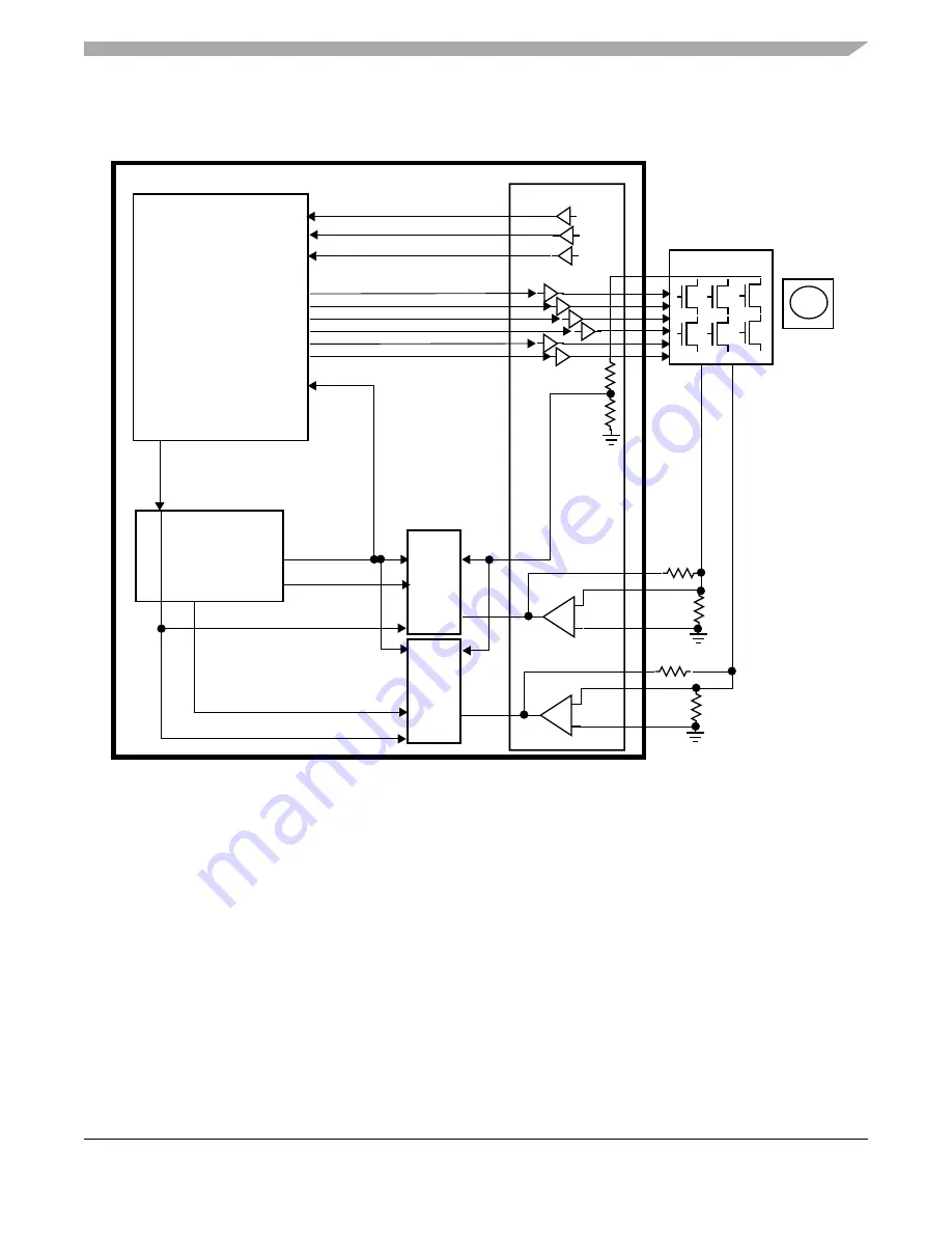
Figure 1-14. Sensorless PMSM Control Loop Configuration
1.13.6.2
PMSM Operation With Sine-Cosine Position Sensor
In this configuration the PMSM stator winding currents are driven sinusoidally and the back EMF
waveform is also sinusoidal. Thus all 3 phases are active simultaneously. The back EMF voltage is
calculated based on the currents. The rotor position and speed are determined by a sine/cosine sensor,
which generates sinusoidal sine/cosine signals, indicating the angle of the rotor in relation to sensor
windings. The sensor is supplied by the EVDD1 pin.
1. Configure PMF for complementary mode operation.
2. Configure PMF for center aligned or phase shifted operation.
3. Select correct PMF deadtime insertion based on external FET switches.
4. Enable GDU current sense opamps for measuring the phase currents from external shunts.
5. Map the output pin of each current sense opamp to the ADC input.
PMF
PTU
ADC0
GDU
M
ADC1
reload
glb_ldok
reload
dc_b
us_current1
dc_bus_voltage
trigger_0
trigger_1
dc_b
us_current0
zero crossing
IS0
IS1
IS2
phase comparison
reloada


