


Chapter 1 Device Overview MC9S12ZVM-Family
MC9S12ZVM Family Reference Manual Rev. 1.3
70
Freescale Semiconductor
current (motor torque), hence smooth full four quadrant control. Usually the center-aligned PWM is
chosen to lower electromagnetic emissions.
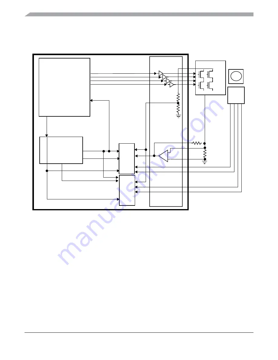
Figure 1-10. BDCM Control Loop Configuration
The PWM frequency selection is always a compromise between audible noise, electromagnetic emissions,
current ripples and power switching losses.
The BDCM control loop goal is to provide a controlled DC voltage to the motor winding, whereby it is
controlled cycle-by-cycle using a speed, current or torque feedback loop.
The center aligned PWM waveforms generated by the PMF module are applied to the bridge as shown in
whereby the base waveform for PWM0 and PWM1 is depicted at the top and the
complementary PWM0 and PWM1 waveforms are shown with deadtime insertion depicted by the gray
phases before the switching edges.
PMF
PTU
ADC0
GDU
M
reload
glb_ldok
dc_bus_voltage
trigger_0
dc_b
us_current0
sine/
sensor
cosine
ADC1
reload
trigger_1
reloada


