


Chapter 1 Device Overview MC9S12ZVM-Family
MC9S12ZVM Family Reference Manual Rev. 1.3
Freescale Semiconductor
73
7. Read port register PTIT[3:1] to determine starting sector.
8. Startup motor by applying PWM to the related motor phase.
9. In IC1 interrupt ISR calculate the delay to next commutation and store value to output compare
register. Update registers with next values of mask and swap.
10. On next output compare event the buffered mask and swap information is transferred to the active
PWM registers to execute the commutation.
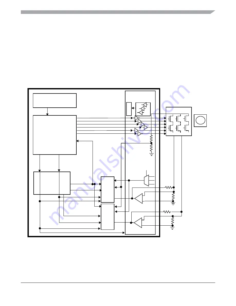
1.13.5.2
Sensorless Commutation
Figure 1-13. Sensorless BLDC Configuration
To calculate the commutation time in a sensorless motor system the back-EMF zero crossing event of the
currently non-fed phase within an electrical rotation cycle must be determined. For fast motor rotation, the
ADC is used to measure the back-EMF voltage and the DC bus voltage to determine the zero crossing time.
For slow motor rotation the GPHS register can be polled. In either case the zero crossing event is handled
PMF
PTU
ADC0
GDU
M
ADC1
reload
glb_ldok
reload
dc_b
us_current1
dc_bus_voltage
trigger_0
trigger_1
dc_b
us_current0
zero crossing
back-EMF
P1
P2
P3
PHMUX
TIM
commutation_event
comparators
GPHS
OC0
async_reload
async_reload
reloada
async_reload


