The Interface
4
32
Lightscape
Tilt
Use Tilt
to tilt the camera, rotating it around an
axis perpendicular to the screen. You change the tilt
view by dragging the mouse in a circular motion in
the Graphic window. The model rotates in the same
direction as the mouse movement.
Tilt is available in all projections.
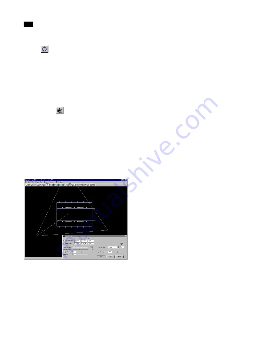
Using View Setup
Use View Setup
to define a specific camera view
of your model.
To use View Setup:
1.
Choose View | Setup, or click the View Setup
button on the View Control toolbar.
The display changes to Top view, the view frustum is
displayed (in red) over the model, and the View
Setup dialog appears.
2.
Set the required options in the View Setup dia-
log, and click OK. The options are explained in the
following sections.
Note:
When using View Setup, you can also use
the following view buttons to adjust your view:
Zoom, Zoom Window, Scroll, and Tilt.
Viewer Position
Use this option to set the camera position. To set this
option, select it and click the point at which to set the
camera position in the Graphic window.
You can also enter the explicit location on the X, Y,
and Z axes in the corresponding input boxes. These
values are in the length units of the model. For more
information, see “Setting Units Properties” on page
46.
Note:
Setting the viewer position by selecting a
point in the Graphic window does not set the Z
(height) value. This value must be explicitly set in
the Z input box.
Focus Point
Use this option to set the point at which the viewer is
focusing. To set this option, select it and click the
required focus point in the Graphic window. You can
also enter the explicit location on the X, Y, and Z axes
in the corresponding input boxes.
Note:
Setting the focus point by selecting a point
in the Graphic window does not set the Z (height)
value. This value must be explicitly set in the Z
input box.
Near Clipping Plane
Use this option to define the location of the near
clipping plane. Objects in the model that are
between the viewer position and the near clipping
plane are not displayed in the Graphic window.
Set the near clipping plane by entering the required
value in the input box or by adjusting the Near Clip
Plane slider.
Far Clipping Plane
Use this option to define the location of the far clip-
ping plane. Objects in the model that are beyond the
far clipping plane are not displayed.
Summary of Contents for LIGHTSCAPE
Page 1: ...SULO 4 31 93 36034333308355 LJKWVFDSH...
Page 18: ...NOTES 10...
Page 110: ...NOTES 102...
Page 136: ...NOTES 128...
Page 166: ...NOTES 158...
Page 176: ...NOTES 168...
Page 202: ...NOTES 194...
Page 210: ...NOTES 202...
Page 248: ...NOTES 240...
Page 294: ...NOTES 286...
Page 308: ...NOTES 300...
Page 316: ...NOTES 308...
Page 324: ...NOTES 316...
Page 342: ...Glossary 334 Lightscape...
Page 360: ...Index ix 352 Lightscape...
Page 362: ......


