Radiosity Processing
11
184
Lightscape
Changing Materials and
Luminaires
Once you have computed a radiosity solution, you
can still modify light sources and materials to fine-
tune the appearance of the final rendering or to
explore different design alternatives.
Rather than restarting the simulation every time you
make a change, the system compensates for the
changes incrementally, starting from the current
solution. This way, you can quickly evaluate the
solution and make refinements to obtain precisely
the look you want.
Changing Surface Materials
In the Solution stage, you assign materials or change
the material properties in the same way as during the
Preparation stage. You can either redefine the prop-
erties of a material or create a new material and
assign it to specific surfaces. For more information,
see Chapter 7, “Using Materials.”
When you change a material, it is immediately
displayed on all surfaces to which it is applied.
However, if the original surface had reflected light
into the environment and caused color bleeding, the
changes in its reflected light contribution are not
calculated or displayed until you run additional iter-
ations of the radiosity process.
Note:
You should reset the solution and restart the
processing if there is considerable color bleeding
or if you have made significant changes to
materials.
Changing Light Values
In addition to changing surface materials, you can
also redefine the characteristics of photometric
luminaires. However, you cannot change the posi-
tion of the luminaire during the Solution process.
You must return to the Preparation model to make
any geometric changes.
Note:
Changes to the lighting characteristics work
properly only if the Disable Solution Changes
parameter is disabled when the solution is
processed. For more information, see “Disable
Solution Changes” on page 174.
When you change a light source, the system
responds by first canceling the original energy
distributed from the light. This is done in the first
iteration. In the second iteration, it adds the direct
illumination for the new light source. Computing
changes in the indirect illumination may require
further iterations.
Meshing Examples
Lightscape represents variations of illumination
across a surface by first breaking the surface into a
mesh, and then using adaptive subdivision to
capture smaller illumination details. To understand
this process and its relation to the processing param-
eters, consider the example of a single spotlight
pointed directly at a surface.
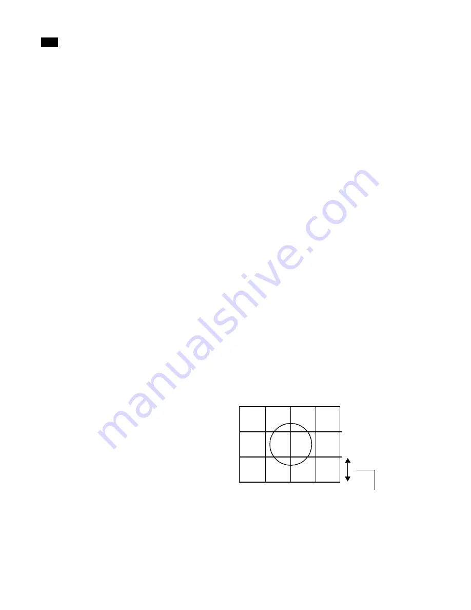
First, the Maximum Mesh Spacing value is used to
create the initial mesh.
The system begins by computing the contribution of
the light source to the vertices of the initial surface
mesh. For each element, the system then compares
Maximum Mesh Spacing
Summary of Contents for LIGHTSCAPE
Page 1: ...SULO 4 31 93 36034333308355 LJKWVFDSH...
Page 18: ...NOTES 10...
Page 110: ...NOTES 102...
Page 136: ...NOTES 128...
Page 166: ...NOTES 158...
Page 176: ...NOTES 168...
Page 202: ...NOTES 194...
Page 210: ...NOTES 202...
Page 248: ...NOTES 240...
Page 294: ...NOTES 286...
Page 308: ...NOTES 300...
Page 316: ...NOTES 308...
Page 324: ...NOTES 316...
Page 342: ...Glossary 334 Lightscape...
Page 360: ...Index ix 352 Lightscape...
Page 362: ......


