PS220 Configuration & Operation Guide
257 PS220
Fault T
racing
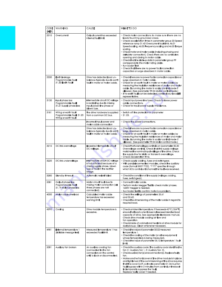
CODE
(HEX)
WARNING
CAUSE
WHAT TO DO
2310
Overcurrent
Output current has exceeded
internal fault limit.
•
Check motor connections to make sure there are no
leads touching grounded areas.
•
Check acceleration times in parameter group 23 Speed
reference ramp 31.42 Overcurrent fault limit, 46.01
Speed scaling, 46.02 Frequency scaling and 46.03 Torque
scaling.
•
Check motor and motor cable (including phasing and
delta/star connection). Check there are no contactors
opening and closing in motor cable.
•
Check that the start-up data in parameter group 99
corresponds to the motor rating plate.
•
Run Scalar Test.
•
Check that there are no power factor correction
capacitors or surge absorbers in motor cable.
2330
Earth leakage
Programmable fault:
31.20 Earth fault
Drive has detected load un-
balance typically due to earth
fault in motor or motor cable.
•
Check there are no power factor correction capacitors or
surge absorbers in motor cable.
•
Check for an earth fault in motor or motor cables by
measuring the insulation resistances of motor and motor
cable. Try running the motor in scalar control mode if
allowed. (See parameter 99.04 Motor control mode.)
•
If no earth fault can be detected, contact your local ITT
representative.
3130
Input phase loss
Programmable fault:
31.21 Supply phase loss
Intermediate circuit DC voltage
is oscillating due to missing
input power line phase or
blown fuse.
•
Check input power line fuses. Check for loose power
cable connections.
•
Check for input power supply imbalance.
3181
Wiring or earth fault
Programmable fault: 31.23
Wiring or earth fault
The drive hardware is supplied
from a common DC bus.
•
Switch off the protection in parameter
•
31.23.
Incorrect input power and
motor cable connection
•
Check the power connections.
Drive has detected load un-
balance typically due to earth
fault in motor or motor cable.
•
Check there are no power factor correction capacitors or
surge absorbers in motor cable.
•
Check for an earth fault in motor or motor cables by
measuring the insulation resistances of motor and motor
cable. Try running the motor in scalar control mode if
allowed. (See parameter 99.04 Motor control mode.)
3210
DC link overvoltage
Excessive intermediate circuit
DC voltage.
•
Check that overvoltage control is on (parameter 30.30
Overvoltage control). Check that the supply voltage
matches the nominal input voltage of the drive. Check
the supply line for static or transient overvoltage.
•
Check deceleration time.
3220
DC link undervoltage
Intermediate circuit DC voltage
is not sufficient because of a
missing supply phase, blown
fuse or fault in the rectifier
bridge.
•
Check supply cabling, fuses and switchgear.
•
With parallel-connected modules, check the auxiliary
code (format XXXY YYZZ). “Y YY” specifies through
which BCU control unit channel the fault was received.
3280
Standby timeout
Automatic restart failed
•
Check the condition of the supply (voltage, cabling,
fuses, switchgear).
3381
Output phase loss
Programmable fault:
31.19 Motor phase loss
Motor circuit fault due to
missing motor connection (all
three phases are not
connected).
•
Connect motor cable.
•
Perform Motor Megger Test to check motor phases.
1600V megger is needed.
•
Run Scalar Test to confirm motor is a problem.
4000
Motor cable overload
Calculated motor cable
temperature has exceeded
warning limit.
•
Check the settings of parameters 35.61
and 35.62.
•
Check the dimensioning of the motor cable in regard to
required load.
4290
Cooling
Drive module temperature is
excessive.
•
Check ambient temperature. If it exceeds 40 °C (104 °F),
ensure that load current does not exceed derated load
capacity of drive. See appropriate Hardware manual.
Check drive module cooling air flow and
fan operation.
•
Check inside of cabinet and heatsink of drive module for
dust pick-up. Clean whenever necessary.
4981
External temperature 1
(Editable message text)
Measured temperature 1 has
exceeded fault limit.
•
Check the value of parameter 35.02 measured
temperature 1.
•
Check the cooling of the motor (or other equipment
whose temperature is being measured).
•
Check the value of parameter 35.12 Temperature 1 fault
limit.
5081
Auxiliary fan broken
An auxiliary cooling fan
(connected to the fan
connectors on the control
unit) is stuck or disconnected.
•
Check the auxiliary code. The auxiliary code identifies the
fan (1: Auxiliary fan 1, 2: Auxiliary fan 2).
•
Check auxiliary fan(s) and connection(s). Replace faulty
fan.
•
Make sure the front cover of the drive module is in place
and tightened. If the commissioning of the drive requires
that the cover is off, activate parameter 31.36 Aux fan
fault bypass within 2 minutes from control unit reboot
to temporarily suppress the fault.
Replace faulty cover if needed.
Содержание PumpSmart PS220
Страница 1: ...Configuration Operation Manual PumpSmart Control Solutions PS220 v6 05...
Страница 5: ...PS220 Configuration Operation Guide PS220 4 Getting Started THIS PAGE IS INTENTIONALLY LEFT BLANK...
Страница 9: ...PS220 Configuration Operation Guide PS220 8 Basic Startup THIS PAGE IS INTENTIONALLY LEFT BLANK...
Страница 22: ...PS220 Configuration Operation Guide 21 PS220 SmartFlow...
Страница 40: ...PS220 Configuration Operation Guide 39 PS220 Process Control THIS PAGE IS INTENTIONALLY LEFT BLANK...
Страница 217: ...PS220 Configuration Operation Guide PS220 216 Functions Features This is an example of a typical Pump Performance Curve...
Страница 261: ...PS220 Configuration Operation Guide PS220 260 THIS PAGE IS INTENTIONALLY LEFT BLANK...
Страница 283: ...PS220 Configuration Operation Guide PS220 282 THIS PAGE IS INTENTIONALLY LEFT BLANK...
Страница 289: ...PS220 Configuration Operation Guide PS220 288 Ecodesign Regulation...
Страница 292: ...PS220 Configuration Operation Guide 291 PS220 Fuses heat dissipation chart...


