PS220 Configuration & Operation Guide
PS220 270
Parameter
Listing
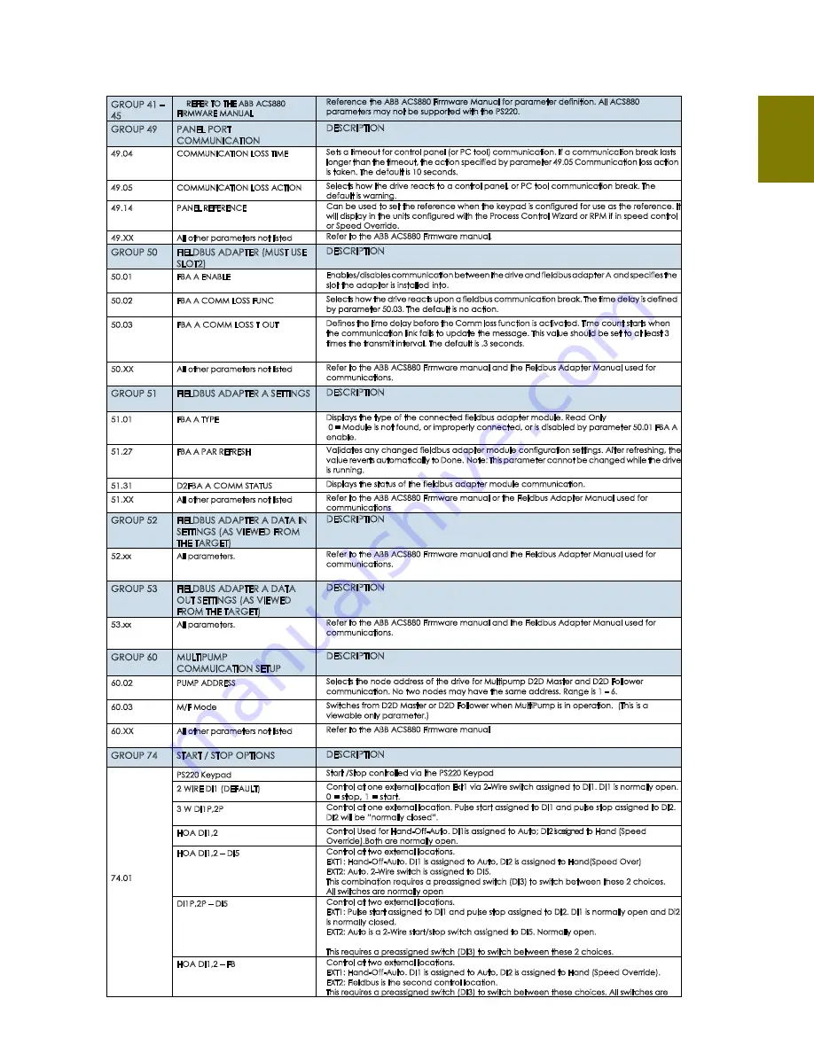
GROUP 41 –
45
REFER TO THE ABB ACS880
FIRMWARE MANUAL
Reference the ABB ACS880 Firmware Manual for parameter definition. All ACS880
parameters may not be supported with the PS220.
GROUP 49
PANEL PORT
COMMUNICATION
DESCRIPTION
49.04
COMMUNICATION LOSS TIME
Sets a timeout for control panel (or PC tool) communication. If a communication break lasts
longer than the timeout, the action specified by parameter 49.05 Communication loss action
is taken. The default is 10 seconds.
49.05
COMMUNICATION LOSS ACTION
Selects how the drive reacts to a control panel, or PC tool communication break. The
default is warning.
49.14
PANEL REFERENCE
Can be used to set the reference when the keypad is configured for use as the reference. It
will display in the units configured with the Process Control Wizard or RPM if in speed control
or Speed Override.
49.XX
All other parameters not listed
Refer to the ABB ACS880 Firmware manual.
GROUP 50
FIELDBUS ADAPTER (MUST USE
SLOT2)
DESCRIPTION
50.01
FBA A ENABLE
Enables/disables communication between the drive and fieldbus adapter A and specifies the
slot the adapter is installed into.
50.02
FBA A COMM LOSS FUNC
Selects how the drive reacts upon a fieldbus communication break. The time delay is defined
by parameter 50.03. The default is no action.
50.03
FBA A COMM LOSS T OUT
Defines the time delay before the Comm loss function is activated. Time count starts when
the communication link fails to update the message. This value should be set to at least 3
times the transmit interval. The default is .3 seconds.
50.XX
All other parameters not listed
Refer to the ABB ACS880 Firmware manual and the Fieldbus Adapter Manual used for
communications.
GROUP 51
FIELDBUS ADAPTER A SETTINGS DESCRIPTION
51.01
FBA A TYPE
Displays the type of the connected fieldbus adapter module. Read Only
0 = Module is not found, or improperly connected, or is disabled by parameter 50.01 FBA A
enable.
51.27
FBA A PAR REFRESH
Validates any changed fieldbus adapter module configuration settings. After refreshing, the
value reverts automatically to Done. Note: This parameter cannot be changed while the drive
is running.
51.31
D2FBA A COMM STATUS
Displays the status of the fieldbus adapter module communication.
51.XX
All other parameters not listed
Refer to the ABB ACS880 Firmware manual or the Fieldbus Adapter Manual used for
communications
GROUP 52
FIELDBUS ADAPTER A DATA IN
SETTINGS (AS VIEWED FROM
THE TARGET)
DESCRIPTION
52.xx
All parameters.
Refer to the ABB ACS880 Firmware manual and the Fieldbus Adapter Manual used for
communications.
GROUP 53
FIELDBUS ADAPTER A DATA
OUT SETTINGS (AS VIEWED
FROM THE TARGET)
DESCRIPTION
53.xx
All parameters.
Refer to the ABB ACS880 Firmware manual and the Fieldbus Adapter Manual used for
communications.
GROUP 60
MULTIPUMP
COMMUICATION SETUP
DESCRIPTION
60.02
PUMP ADDRESS
Selects the node address of the drive for Multipump D2D Master and D2D Follower
communication. No two nodes may have the same address. Range is 1 – 6.
60.03
M/F Mode
Switches from D2D Master or D2D Follower when MultiPump is in operation. (This is a
viewable only parameter.)
60.XX
All other parameters not listed
Refer to the ABB ACS880 Firmware manual
GROUP 74
START / STOP OPTIONS
DESCRIPTION
74.01
PS220 Keypad
Start /Stop controlled via the PS220 Keypad
2 WIRE DI1 (DEFAULT)
Control at one external location Ext1 via 2-Wire switch assigned to DI1. DI1 is normally open.
0 = stop, 1 = start.
3 W DI1P,2P
Control at one external location. Pulse start assigned to DI1 and pulse stop assigned to DI2.
DI2 will be “normally closed”.
HOA DI1,2
Control Used for Hand-Off-Auto. DI1is assigned to Auto; DI2 is assigned to Hand (Speed
Override).Both are normally open.
HOA DI1,2 – DI5
Control at two external locations.
EXT1: Hand-Off-Auto. DI1 is assigned to Auto, DI2 is assigned to Hand(Speed Over)
EXT2: Auto. 2-Wire switch is assigned to DI5.
This combination requires a preassigned switch (DI3) to switch between these 2 choices.
All switches are normally open
DI1P,2P – DI5
Control at two external locations.
EXT1: Pulse start assigned to DI1 and pulse stop assigned to DI2. DI1 is normally open and Di2
is normally closed.
EXT2: Auto is a 2-Wire start/stop switch assigned to DI5. Normally open.
This requires a preassigned switch (DI3) to switch between these 2 choices.
HOA DI1,2 – FB
Control at two external locations.
EXT1: Hand-Off-Auto. DI1 is assigned to Auto, DI2 is assigned to Hand (Speed Override).
EXT2: Fieldbus is the second control location.
This requires a preassigned switch (DI3) to switch between these choices. All switches are
Содержание PumpSmart PS220
Страница 1: ...Configuration Operation Manual PumpSmart Control Solutions PS220 v6 05...
Страница 5: ...PS220 Configuration Operation Guide PS220 4 Getting Started THIS PAGE IS INTENTIONALLY LEFT BLANK...
Страница 9: ...PS220 Configuration Operation Guide PS220 8 Basic Startup THIS PAGE IS INTENTIONALLY LEFT BLANK...
Страница 22: ...PS220 Configuration Operation Guide 21 PS220 SmartFlow...
Страница 40: ...PS220 Configuration Operation Guide 39 PS220 Process Control THIS PAGE IS INTENTIONALLY LEFT BLANK...
Страница 217: ...PS220 Configuration Operation Guide PS220 216 Functions Features This is an example of a typical Pump Performance Curve...
Страница 261: ...PS220 Configuration Operation Guide PS220 260 THIS PAGE IS INTENTIONALLY LEFT BLANK...
Страница 283: ...PS220 Configuration Operation Guide PS220 282 THIS PAGE IS INTENTIONALLY LEFT BLANK...
Страница 289: ...PS220 Configuration Operation Guide PS220 288 Ecodesign Regulation...
Страница 292: ...PS220 Configuration Operation Guide 291 PS220 Fuses heat dissipation chart...


