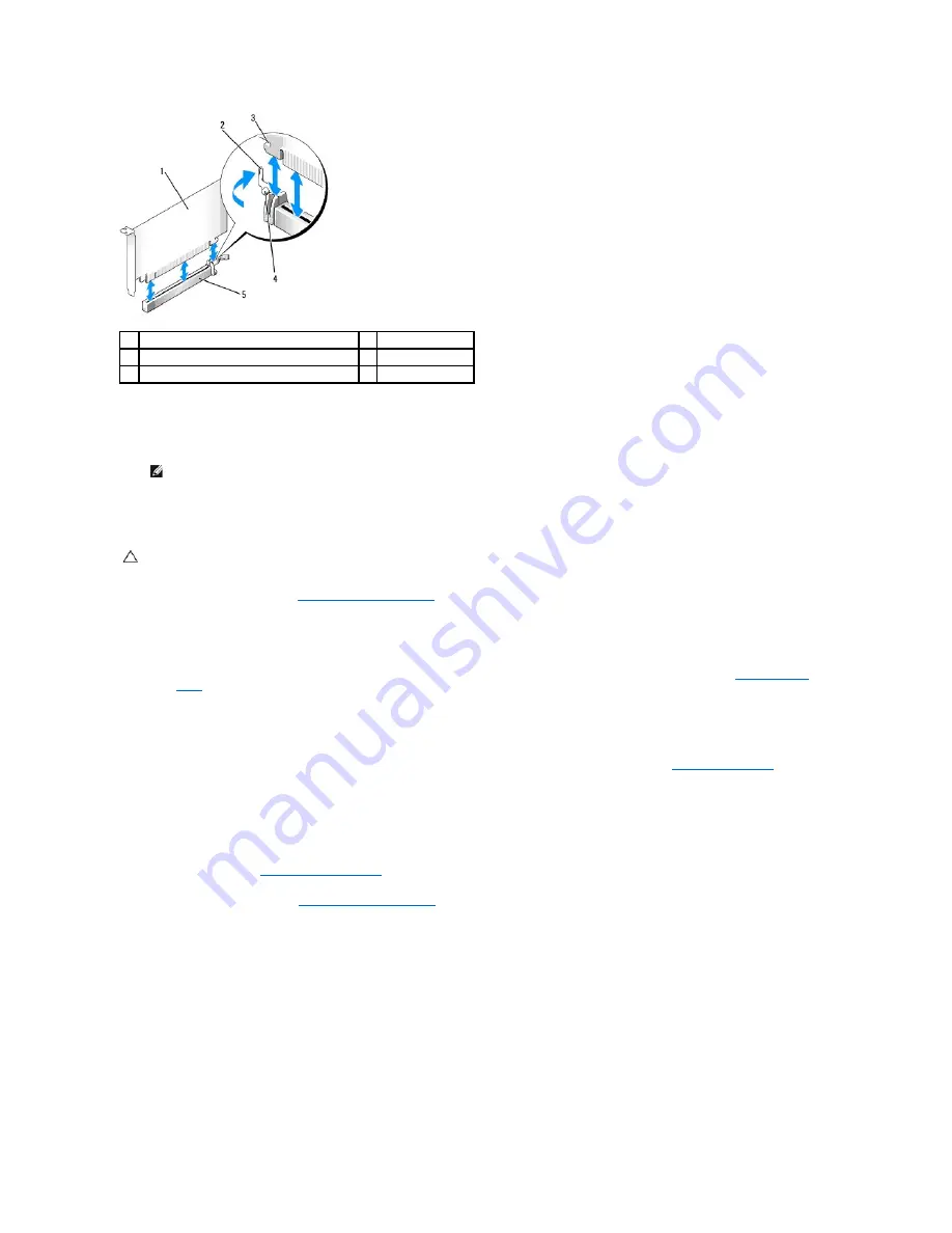
6.
Grasp the card by its top corners, and ease it out of its connector.
7.
If you are removing the card permanently, install a filler bracket in the empty card-slot opening.
8.
Rotate the release tab downward to snap the card-retention latch into place.
9.
Replace the computer cover (see
Replacing the Computer Cover
), reconnect the computer and devices to electrical outlets, and then turn them on.
10.
Uninstall the card's driver. See the documentation that came with the card for instructions.
11.
If you removed a sound card:
a.
Enter system setup, select
System Configuration
®
Miscellaneous Devices
, and change the
Audio
setting to
Enabled
(see
Entering System
Setup
).
b.
Connect external audio devices to the sound card's connectors. Do not connect external audio devices to the microphone, speaker/headphone,
or line-in connectors on the back panel of the computer.
12.
If you removed a network adapter card and want to turn on the integrated network adapter:
a.
Enter system setup, select
System Configuration
®
Integrated NIC
, and change the setting to
Enabled
(see
Entering System Setup
).
b.
Connect the network cable to the integrated the back panel of the computer.
Removing a PCI Card From the Riser-Card Cage
1.
Follow the procedures in
Working on Your Computer
.
2.
Remove the computer cover (see
Removing the Computer Cover
).
3.
Remove the riser-card cage:
a.
Check any cables connected to cards through the back panel openings. Disconnect any cables that will not reach the riser-card cage once they
are removed from the computer.
b.
Gently pull on the handle and lift the riser-card cage up and away from the computer.
1
PCI Express x16 card
2
release lever
3
securing slot (not all cards)
4
securing tab
5
PCI Express x16 card connector
NOTE:
Installing filler brackets over empty card-slot openings is necessary to maintain FCC certification of the computer. The brackets keep dust
and dirt out of your computer and maintain the airflow that cools your computer.
CAUTION:
To connect a network cable, first plug the cable into the network wall jack and then plug it into the computer.
Содержание OptiPlex 760
Страница 29: ......
Страница 48: ......
Страница 56: ...Back to Contents Page 17 PS 2 or serial connector SERIAL2 18 floppy connector DSKT 19 fan connector FAN_CPU ...
Страница 101: ......
Страница 106: ...Back to Contents Page 1 release knob ...
Страница 140: ...5 Replace the computer cover 6 Turn on power to the computer Back to Contents Page ...
Страница 143: ...Back to Contents Page 19 fan connector FAN_CPU ...
Страница 146: ...Desktop System Board Screws Small Form Factor System Board Screws 1 screws 9 1 screws 9 ...
Страница 148: ...Back to Contents Page ...
Страница 157: ...Mini Tower Desktop Small Form Factor Ultra Small Form Factor ...
Страница 194: ...7 Replace the cable cover if used Back to Contents Page ...
Страница 196: ...Back to Contents Page ...
Страница 199: ...5 Replace the computer cover 6 Turn on power to the computer Back to Contents Page ...


