background image

E6582062

1-9

1. Read first

1

3

9

10

1. 4. 2

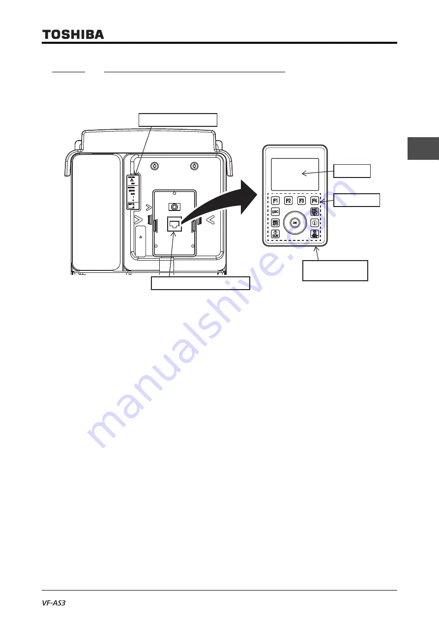
Operation panel and peripherals

The operation panel of the inverter is directly connected to RS485 communication connector 1.
It is equipped with some indicators for inverter status on the left side of the operation panel.

Operation panel

The operation panel is equipped with a LCD screen and operation keys on the front side and two
types of connectors (operation panel female connector and USB-miniB connector) on the bottom
surface.
It is directly connected to the unit with the operation panel male connector on the back side but can
be removed. It can be also used for remote control with Door mounting kit (SBP010Z) and an
exclusive cable (optional), see [10. 3. 8] for detail.

• LCD screen

The operation panel is equipped with a multilingual (8 languages) LCD that displays the frequency,
parameters and their set values and the operation status according to the display mode of the
inverter. For details, refer to [3. 1. 1].

• Operation keys

There are an [ESC] key, [HAND/AUTO] key, [RUN] key, [FWD/REV] key, [i] key, [STOP/RESET] key,
[F1] to [F4] keys, touch wheel, and [OK] key.
The [F1] to [F4] keys execute functions according to the indication on the lower side of the LCD
screen.
With the touch wheel, you can change the menu items and values on the screen by touching it by
your finger to rotate to the right or left or touching its upper side or lower side lightly.
For details of the operation keys, refer to [3. 1. 1].

• Operation panel lower side cover

This cover protects two connectors on the right of the lower side of the operation panel and the slot for
battery on the left. The right side/left side of the cover can be opened respectively.

Indicator for inverter status

RS485 communication connector 1

LCD screen

Operation keys

Operation panel lower 
side cover

Summary of Contents for TOSVERT VF-AS3

Page 1: ...andards 9 Selection and installation of peripheral devices 10 Table of parameters 11 Specifications 12 Trip information and measures 13 Maintenance and inspection 14 Warranty 15 Disposal 16 17 18 Industrial Inverter For 3 phase motors Instruction Manual High performance inverter 3 phase 240V class 0 4 to 55kW 3 phase 480V class 0 4 to 280kW Notice 1 Make sure that this instruction manual is delive...

Page 2: ...1 9 ...

Page 3: ...to death or serious injury CAUTION Indicates that errors in operation will lead to injury 1 to people or that these errors will cause damage to physical property 2 1 Such things as injury burns or electric shock that will not require hospitalization or long periods of outpatient treatment 2 Physical property damage refers to wide ranging damage to assets and materials Marking Meaning of marking In...

Page 4: ...ssembly inhibited Never disassemble modify or repair This can result in electric shock fire and other injury Please call your Toshiba distributor for repairs Prohibited Never remove the front cover when the power is on The unit contains high voltage parts and contact with them will result in electric shock Do not stick your fingers into openings such as cable wiring holes and cooling fan covers Th...

Page 5: ...nual Operations under any other conditions will result in failure Mount the inverter on a metal plate The rear panel will get high temperature Do not mount the inverter on an inflammable object this will result in fire Do not operate the inverter with the front cover removed The unit contains high voltage parts and contact with them will result in electric shock An emergency stop device must be in...

Page 6: ... inverter is hanged by two wire ropes in a balanced manner and please be careful that the inverter does not receive excessive force during the hanging operation Do not carry the inverter with the cover attached hold nor put the hand in the wiring holes during the transportation You can have your hands pinched and injured Transport the operation panel in accordance with law Please transport the ope...

Page 7: ...e capacity of the grounding capacitor should not be increased Otherwise it will result in failure or fire Mandatory action Electrical construction work must be done by a qualified expert Erroneous connection of power supply by someone who does not have that expert knowledge will result in fire or electric shock Connect output terminals motor side correctly If the phase sequence is incorrect the mo...

Page 8: ...el from the unit Do not connect Ethernet to the RS485 communication connector Erroneous connection will result in failure Do not connect RS485 communication to the Ethernet connector Erroneous connection will result in failure Mandatory action Verify that the power is OFF before detaching the front cover If you detach the front cover while the power is ON this will result in electric shock or othe...

Page 9: ...mage the inverter or cause the inverter to perform unexpected movement Make sure to set the parameter correctly If you set the parameter incorrectly this will damage the inverter or cause the inverter to perform unexpected movement When you write the parameter in the inverter via a parameter writer or operation panel please transmit correct data Make sure that operation instructions are off before...

Page 10: ...If the parameter is not properly set the inverter cannot be stopped immediately and this will result in injury and accidents Install an emergency stop device and an interlock that are configured in accordance with the system specifications If the inverter cannot be stopped immediately via communication or the extension panel this will result in injury and accidents Caution Mandatory action When th...

Page 11: ...ing the PM motor please verify that the PM motor is stopped While the PM motor is rotating even after the power is turned off as a high voltage is generated in the output terminals U T1 V T2 and W T3 on the PM motor side touching the output terminals will result in electric shock Caution Mandatory action If you dispose of the inverter have it done by a specialist in industry waste disposal 1 If yo...

Page 12: ... for Auto restart Do not go near motors and equipment Motors and machines that have stopped temporarily due to momentary power failure will restart suddenly after power is restored Caution Functions programmed for Retry Do not go near motors and equipment Motors and machines that have stopped temporarily due to tripping stop will restart suddenly after the specified time has elapsed and alarm cond...

Page 13: ... manual explains how to install and wire the inverter operation procedure how to run the motor measures for protective functions when an alarm trip occurs etc It is for the Ver 100 and later CPU versions of the inverter Please be informed that the specifications described in the instruction manual and technical data and the CPU version may be changed without notice II Introduction ...

Page 14: ......

Page 15: ...ls from the control terminals 6 1 6 2 Input signals to the control terminals 6 7 6 3 Selecting terminal functions 6 12 6 4 Switching two to four types of motor characteristics 6 16 6 5 V f 5 point setting 6 19 6 6 Setting the frequency commands 6 20 6 7 Setting the start and end frequencies 6 32 6 8 DC braking 6 36 6 9 Automatic stop when run continues at the lower limit frequency sleep function 6...

Page 16: ...ith safety standards 9 11 10 Selection and installation of peripheral devices 10 1 10 1 Selection of wire size 10 1 10 2 Selection of a wiring device 10 4 10 3 External options 10 10 10 4 Insert type options 10 14 11 Table of parameters 11 1 11 1 Frequency setting parameter 11 1 11 2 Basic parameter 11 2 11 3 Extended parameter 11 6 11 4 Advanced parameter 11 48 11 5 Communication parameter 11 49 ...

Page 17: ...E6582062 iii I 3 9 15 Warranty 15 1 16 Disposal 16 1 ...

Page 18: ......

Page 19: ...sed check to make sure that it is exactly what you ordered Check the contents of packing and accessories for damage 1 Read first 1 1 Check product purchase CAUTION Mandatory action Use the inverter that conforms to specifications of the power supply and the three phase motor to be operated If you use the inappropriate inverter not only will the three phase motor not rotate correctly but it will ca...

Page 20: ...d domestic components Inverter type Inverter rated output capacity Rated voltage Rated input current Rated output current Name plate Rating label Model name Rated voltage Applicable motor capacity Inverter main unit Rating label Name plate Danger label Carton box Type indication label Danger label Refer to 1 2 for HD and ND ...

Page 21: ...DC reactor to the inverter by referring to 2 3 8 Quick start CD ROM Instruction manual is included as electronic data Profinet DeviceNet Profibus CANopen Danger label kit French German Italian Spanish Chinese Japanese Danger labels in 6 languages for sticking Labels for communication option Affix to lower side of communication indicator DC reactor Only for frame size A7 and A8 ...

Page 22: ...teristic Example Fans pumps blowers etc AUL 3 HD rating 150 60s 0 after execution Select it to apply equipment with constant torque characteristic Example Conveyors load transporting machinery cranes mixers compressors making machines machine tools etc Both of them return to 0 after setting For details refer to 5 3 2 This instruction manual describes the motor capacity based on HD rating In the ca...

Page 23: ...S3 4004PC to 4037PC A2 VFAS3 2037P VFAS3 4055PC 4075PC A3 VFAS3 2055P 2075P VFAS3 4110PC to 4185PC A4 VFAS3 2110P to 2185P VFAS3 4220PC to 4370PC A5 VFAS3 2220P to 2370P VFAS3 4450PC to 4750PC VFAS3 4 004 P C E Model name Input voltage TOSVERT VF AS3 series E IP55 type Additional function II C Built in EMC filter Additional function I P Equipped Operation panel 2 200 V 240 V 4 380 V 480 V Applicab...

Page 24: ...E6582062 1 Read first 1 6 1 9 A6 VFAS3 2450P 2550P VFAS3 4900PC to 4132KPC A7 VFAS3 4160KPC A8 VFAS3 4200KPC to 4280KPC Frame size Type Form 240V 480V ...

Page 25: ...2 2 Front cover A cover for the terminal blocks power circuit control circuit This cover should be removed for wiring to the power terminal block or the control terminal block using the connector for communication and the option slot switching the grounding capacitor or checking the charge lamp For how to remove refer to 2 2 1 4 Structure of equipment Indicator for communication Front cover Cable ...

Page 26: ... how to remove refer to 2 2 With frame size A4 or A5 VFAS3 2110P to 2370P VFAS3 4220PC to 4750PC Wiring cover The models with frame size A4 or A5 have a cover for wiring beneath the front cover This cover should be removed to wire to the power terminal block or control terminal block For how to remove refer to 2 2 2 frame size A4 or 2 2 3 frame size A5 Indicator for communication Front cover Front...

Page 27: ...nguages LCD that displays the frequency parameters and their set values and the operation status according to the display mode of the inverter For details refer to 3 1 1 Operation keys There are an ESC key HAND AUTO key RUN key FWD REV key i key STOP RESET key F1 to F4 keys touch wheel and OK key The F1 to F4 keys execute functions according to the indication on the lower side of the LCD screen Wi...

Page 28: ...fer to 14 2 2 RS485 communication connector 1 Normally this connector is used for connection of the operation panel For remote control connect the operation panel with an exclusive extension cable optional LED indicators The upper three LEDs indicate the operation status trip status and STO Safe Torque Off respectively from the top STATUS Green LED On Stopped Fast blinking Run command ON frequency...

Page 29: ...s and arrangements depending on the type of the inverter The following figure shows an example of frame size A1 Power terminal block A cage type or screw type terminal block to which the power supply and motor braking resistor etc are connected For details of the terminal types and functions refer to 2 3 3 Grounding terminal Exclusive terminal to wire a grounding wire Charge lamp While the charge ...

Page 30: ...input terminal The default setting is PLC external power supply side For details refer to 2 3 5 RS485 communication connector 2 RS485 COM 2 An RJ45 connector for RS485 communication For details refer to 2 3 6 Ethernet connector 1 2 Two RJ45 connectors for Ethernet are equipped For details refer to 2 3 7 Option slot A B Two slots are equipped in the back of the control terminal block The right one ...

Page 31: ...gh environmental friendliness and enhanced environment resistance A DC reactor built in as standard suppresses generation of harmonics to comply with IEC61000 3 12 An EMC noise filter is built in as standard to comply with C2 C3 480 V class of IEC61800 3 Comply with the chemicals 3C3 dust 3S3 standards of IEC60721 3 3 Frame size A6 or smaller Can be used at an altitude of up to 4800 m TN TT system...

Page 32: ...c 2 3 5 Control terminals Installation of insert type options If necessary 10 4 Selection of built in options Wiring Power terminal block 2 3 2 Standard connection method 2 3 3 Power terminal Mounting of DC reactor 2 3 8 Mounting of DC reactor Control terminal block 2 3 2 Standard connection method 2 3 5 Control terminal Connection of communication cables 2 3 6 RS485 RS485 communication connectors...

Page 33: ...of initial power ON Only at the initial power on the following settings are required SEt Region setting check Quick start 5 3 10 Automatic setting of main parameters by region used AUL Multi rating select 1 2 Multi rating 5 3 2 Selecting an overload protection characteristic Setting of LCD screen 3 1 3 Setting of LCD screen Setting of parameters Chapter 4 Chapter 5 and Chapter 6 Attachment of caut...

Page 34: ......

Page 35: ...ling fan covers The unit contains high voltage parts and contact with them will result in electric shock Do not place or insert any kind of object electrical wire cuttings rods wires etc inside the inverter This will cause a short circuit and result in electric shock or fire Do not allow water or any other fluids to come in contact with the inverter This will cause a short circuit and result in el...

Page 36: ...oid locations where there is exposure to water and or where there may be large amounts of dust metallic fragments and oil mist 2 1 Installation WARNING Prohibited Do not place any inflammable object near the inverter If flame is emitted due to failure in the inverter this will lead to fire Do not install the inverter in any location where the inverter could come into contact with water or other fl...

Page 37: ...n the positions shown in the figure on the right 4 Do not touch the heat sink as it may have a high temperature 5 Do not install in any location subject to large amounts of vibration If the inverter is installed in a location that is subject to vibration anti vibration measures are required Please consult with your Toshiba distributor about these measures 6 If the inverter is installed near any of...

Page 38: ...k An emergency stop device must be installed that is configured in accordance with the system specifications If such an emergency stop device that can activate mechanical brake by shutting off power supply is not installed operation cannot be stopped immediately by the inverter alone thus resulting in an accident or injury All options to be used must be those specified by Toshiba The use of option...

Page 39: ...e the inverter with the operation panel removed and use the inverter with the output current reduced refer to Instruction manual for load reduction The space shown in the figure above is the minimum allowable space Because the inverter has cooling fans built in on the top or bottom surfaces make the space on top and bottom as large as possible to allow for air passage Type H1 cm H2 cm H3 cm VFAS3 ...

Page 40: ... setting of carrier frequency For details refer to Instruction manual for load reduction E6582116 Calorific values of inverter and required ventilation The inverter will lose the power slightly as a result of conversion from AC to DC or from DC to AC In order to suppress the rise in temperature inside the cabinet when this loss becomes heat loss the interior of the cabinet must be ventilated and c...

Page 41: ...rge surface quantity m2 3 phase 240 V 0 75 VFAS3 2004P A1 65 27 0 37 1 30 1 5 2007P 92 29 0 52 1 83 2 2 2015P 115 32 0 65 2 31 4 0 2022P 189 38 1 07 3 79 5 5 2037P A2 243 47 1 38 4 85 7 5 2055P A3 392 53 2 22 7 84 11 2075P 544 62 3 09 10 87 15 2110P A4 625 90 3 55 12 51 18 5 2150P 750 101 4 26 15 01 22 2185P 874 112 4 96 17 49 30 2220P A5 1084 136 6 15 21 68 37 2300P 1384 163 7 86 27 68 45 2370P 1...

Page 42: ...n any magnetic contactor and relay coils used around the inverter Install radio noise reduction filters if necessary Input voltage Class Applicable motor capacity kW Inverter type form Frame size Inverter calorific value W 1 Inner side calorific value W 1 Forced air cooled Required ventilation amount m3 min Sealeded cabinet Necessary heat discharge surface quantity m2 3 phase 480 V 0 75 VFAS3 4004...

Page 43: ...n air deflecting plate so that the heat rising up from the inverter on the bottom does not affect the inverter on the top Inverters may be installed side by side with each other with no space left between them When installing inverters side by side remove the top cover of the inverter For how to remove refer to 2 2 When using the inverter in locations with temperatures above 50 C use the inverter ...

Page 44: ...moval of installed inverters with frame sizes A1 to A5 Use the procedure and corresponding figure for each type shown in following pages to remove por tions such as covers 2 2 How to remove covers of inverter WARNING Prohibited Never remove the front cover when the power is on The unit contains high voltage parts and contact with them will result in electric shock CAUTION Mandatory action When rem...

Page 45: ... cover Since the screws are of falling prevention type they do not come off the front cover even if loosened 2 Hold the both side of the front cover and pull it slightly down ward The inserted part of the upper side of the front cover comes off The tab shown in the figure on the right also come off 3 Pull the front cover toward you and remove it from the unit 4 Mount the front cover in the reverse...

Page 46: ... unit adjust the position of the tab push the cover to fit in 2 2 2 With frame size A4 VFAS3 2110P to 2185P VFAS3 4220PC to 4370PC The parts to be removed are as follows Front cover in the middle of the front surface resin Wiring cover on the lower side of the front surface resin Top cover on the top surface resin Each cover can be removed separately Important Since the tab is engaged stiffly remo...

Page 47: ...dure Wiring cover 1 Loosen two screws of the wiring cover Since the screws are of falling prevention type they do not come off the wiring cover even if loosened 2 Remove the wiring cover from the unit 3 Mount the wiring cover in the reverse procedure Top cover 1 Put your fingers in the clearance in the back from the upper side of the top cover and pull the cover toward you to remove it The tab sho...

Page 48: ...cover can be removed separately Front cover 1 Remove four screws of the front cover Store the removed screws so as not to be lost 2 Remove the front cover from the unit 3 Mount the front cover in the reverse procedure Wiring cover 1 Remove four screws of the wiring cover Store the removed screws so as not to be lost 2 Remove the wiring cover from the unit 3 Mount the wiring cover in the reverse pr...

Page 49: ... top cover upward and remove it from the unit 4 Mount the top cover in the reverse procedure 2 2 4 With frame size A6 VFAS3 2450P 2550P VFAS3 4900PC to 4132KPC The parts to be removed are as follows Front cover on the lower side of the front surface metal Transparent cover inside the front cover above transparent resin Wiring duct inside the front cover above black resin The top cover is never rem...

Page 50: ...moved just by lifting it 3 Mount the front cover in the reverse procedure Transparent cover 1 Remove the front cover Refer to the procedure above 2 Remove the tab that holds down the transparent cover lift the transparent cover and remove it from the unit The transparent cover is just to be fitted in It has no screw 3 Mount the transparent cover in the reverse procedure Wiring duct 1 Remove the fr...

Page 51: ...7 and A8 VFAS3 4160KPC VFAS3 4200KPC to 4280KPC Here is a case of frame size A7 Except for its wider unit frame size A8 has the same enclosure and structure as frame size A7 The parts to be removed are as follows Front cover lower on the lower side of the front surface metal Transparent cover inside the front cover above trans parent resin Wiring duct inside the front cover above white resin DC re...

Page 52: ... Press and bend the wiring duct lightly by hand and remove two tabs on the right of the transparent cover from the fitting holes of the wiring duct The tabs of the transparent cover are just fitted in 3 Lift the right side of the transparent cover first and remove it from the unit The transparent cover is just fitted in and has no screw Be careful that two bolt holes on the left side of the transp...

Page 53: ...move the front cover lower and the transparent cover Refer to the procedure above 2 Remove two screws of Duct cover Store Duct cover and screws so as not to be lost 3 Remove two nuts of the wiring duct Store the removed nuts so as not to be lost Wiring duct and Duct cover Screw Nut ...

Page 54: ... sure to mount the wiring duct before the transpar ent cover DC reactor cover 1 Remove four screws of the DC reactor cover Store the removed screws so as not to be lost 2 Lift the lower end of the DC reactor cover slightly and remove it from the unit by pulling down The upper side of the DC reactor cover is to be inserted 3 Mount the DC reactor cover in the reverse procedure Wiring duct and Duct c...

Page 55: ...unt the front cover upper in the reverse procedure First fit the upper end of the front cover upper in two tabs of the unit Be sure to mount the front cover upper before the front cover lower and the DC reactor cover 2 2 6 Charge lamp While the charge lamp is on red voltage is applied or high voltage remains in the inverter The location of the charge lamp varies depending on the type With frame si...

Page 56: ...er and pull it slightly downward The inserted part of the upper side of the front cover comes off The tab shown in the figure on the right also come off 3 Pull the front cover toward you and remove it from the unit 4 Check that the charge lamp is on off 5 Mount the front cover in the reverse procedure Pay attention to engagement of the tab and insertion of the upper side of the cover Front cover T...

Page 57: ...ize A2 VFAS3 2037P VFAS3 4055PC 4075PC Frame size A3 VFAS3 2055P 2075P VFAS3 4110PC to 4185PC Frame size A4 VFAS3 2110P to 2185P VFAS3 4220PC to 4370PC Frame size A5 VFAS3 2220P to 2370P VFAS3 4450PC to 4750PC Charge lamp Charge lamp Charge lamp Charge lamp ...

Page 58: ... A6 to A8 VFAS3 2450P 2550P VFAS3 4900PC to 4280KPC You can check the charge lamp without opening the cover When removing the front cover be sure to check that the charge lamp is off Charge lamp Charge lamp Charge lamp Frame size A6 Frame size A7 Frame size A8 ...

Page 59: ...en they are not installed in the cabinet this will result in electric shock WARNING Prohibited Never remove the front cover when the power is on The unit contains high voltage parts and contact with them will result in electric shock Mandatory action Mount the front cover after wiring If you turn the power on without attaching the front cover this will result in electric shock or other injury Elec...

Page 60: ...s of electric wires used in the power circuit refer to the table in 10 1 The length of each wire is assumed to be 30 m or less If the wire length is over 30 m the wire size diameter must be increased For grounding terminal use wires of the size that is equivalent to or larger than those given in table 10 1 and always ground the inverter Wire the grounding wire as close as possible to the inverter ...

Page 61: ... instruction manual Do not touch wires of equipment e g ELCB that is connected to the inverter power side at least 15 minutes after turning off the power If an electric charge remains in a capacitor in the inverter touching the wires before the indicated time will result in electric shock Be grounded The grounding wire must be connected securely If the grounding wire is not securely connected when...

Page 62: ...h a DC power supply a circuit to suppress an inrush current should be required When VFAS3 4160KPC to 4280KPC are used with a DC power supply three phase power input for cooling fan driving should be prepared separately For details refer to application manual DC power supply connect to inverter E6582156 Connection procedure of power circuit wiring The following is the connection procedure of the po...

Page 63: ...rminal Mount ferrules with insulation sleeve terminal and crimp style terminal with insulation sleeve to the end of each wire of the motor in advance For cautions refer to Wiring of 2 3 1 6 Tighten the screws of the terminals U T1 V T2 and W T3 and a terminal PE For the recommended tightening torque refer to Recommended tightening torque of power terminal screws of 2 3 3 Pass the cable Cable Tight...

Page 64: ...2 and T L3 and a terminal PE after passing it through other cable clamp For the recommended tightening torque of the screws refer to Recommended tightening torque of power terminal screws of 2 3 3 Also fix the power supply wiring with the cable clamp The cable clamp exists only in frame size A1 to A5 9 When connection is complete mount the front cover For how to mount refer to 2 2 1 Tighten the tw...

Page 65: ...rical specification of each terminal refer to 2 3 5 For details of how to operate with terminal input refer to 4 4 For an example of wiring of the control circuit refer to the Standard connection diagram Standard connection diagram This diagram shows a standard wiring of the power circuit and control circuit Memo For the layout and shape of power terminal block of each frame size refer to 2 3 3 Th...

Page 66: ...er supply Set F647 Control power option failure detection to back up the control power supply For details refer to 6 30 20 7 The reset signal is activated by ON OFF trigger input 8 Connect to power to comply with OVC2 Over Voltage Category 2 Isolation transformer is necessary when connecting to power supply OVC3 SU CC FLA FLB FLC R1A R2A R1C R2C FM AM CC RX II RR PP STOB STOA PLC PLC SINK SOURCE S...

Page 67: ...supply Set F647 Control power option failure detection to back up the control power supply For details refer to 6 30 20 7 The reset signal is activated by ON OFF trigger input 8 Connect to power to comply with OVC2 Over Voltage Category 2 Isolation transformer is necessary when connecting to power supply OVC3 SU CC FLA FLB FLC R1A R2A R1C R2C FM AM CC RX II RR PP STOB STOA PLC 6 1 3 4 2 2 6 Power ...

Page 68: ...d in conjunction with the inverter internal power supply Set F647 Control power option failure detection to back up the control power supply For details refer to 6 30 20 8 The reset signal is activated by ON OFF trigger input 9 Connect to power to comply with OVC2 Over Voltage Category 2 Isolation transformer is necessary when connecting to power supply OVC3 SU CC FLA FLB FLC OFF ON b contact of o...

Page 69: ...rol power supply unit CPS002Z is required In this case it is used in conjunction with the inverter internal power supply Set F647 Control power option failure detection to back up the control power supply For details refer to 6 30 20 8 The reset signal is activated by ON OFF trigger input 9 Connect to power to comply with OVC2 Over Voltage Category 2 Isolation transformer is necessary when connect...

Page 70: ...y Set F647 Control power option failure detection to back up the control power supply For details refer to 6 30 20 7 The reset signal is activated by ON OFF trigger input 8 Connect to power to comply with OVC2 Over Voltage Category 2 Isolation transformer is necessary when connecting to power supply OVC3 SU CC FLA FLB FLC R1A R2A R1C R2C FM AM CC RX II RR PP STOB STOA PLC PLC SINK SOURCE SW1 5 6 1...

Page 71: ...power supply Set F647 Control power option failure detection to back up the control power supply For details refer to 6 30 20 7 The reset signal is activated by ON OFF trigger input 8 Connect to power to comply with OVC2 Over Voltage Category 2 Isolation transformer is necessary when connecting to power supply OVC3 P24 S5 S4 S3 S2 S1 RES R F SU CC FLA FLB FLC R1A R2A R1C R2C FM AM CC RX II RR PP S...

Page 72: ...is used in conjunction with the inverter internal power supply Set F647 Control power option failure detection to back up the control power supply For details refer to 6 30 20 8 The reset signal is activated by ON OFF trigger input 9 Connect to power to comply with OVC2 Over Voltage Category 2 Isolation transformer is necessary when connecting to power supply OVC3 SU CC FLA FLB FLC OFF ON b contac...

Page 73: ...the control power supplied from the inverter an optional control power supply unit CPS002Z is required In this case it is used in conjunction with the inverter internal power supply 8 The reset signal is activated by ON OFF trigger input 9 Connect to power to comply with OVC2 Over Voltage Category 2 Isolation transformer is necessary when connecting to power supply OVC3 FP Pulse counter Digital in...

Page 74: ... to a braking resistor Change the parameters F304 Dynamic braking OLr trip F308 Braking resistance and F309 Braking resistor capacity if necessary Frame size A1 A2 A3 A4 A5 and A7 BU BU Inside the inverter Connected to a braking unit optional Braking resistor optional is connected to a braking unit terminals PA and PB Frame size A8 PA PC A DC power can be input For models of VFAS3 2110P to 2550P a...

Page 75: ...3 10 M5 A3 2 6 23 18 M8 A4 5 0 44 3 28 AWG2 or smaller 10 88 5 28 AWG1 or bigger M10 A6 27 239 M12 A5 10 88 5 35 AWG1 0 or smaller 18 159 35 AWG2 0 or bigger M12 A7 A8 41 360 M10 A7 24 212 M4 A7 A8 1 4 12 4 Screw size Frame size Torque Strip length mm Cable size N m lb in M5 A1 A2 A3 2 6 23 M6 A4 4 4 38 9 M8 A4 5 0 44 3 28 AWG2 or smaller 10 88 5 28 AWG1 or bigger M8 A5 A6 11 8 104 M10 A6 27 239 M...

Page 76: ... 4075PC CAUTION Mandatory action Following type of screwdriver should be used for M4 screw PH2 phillips bit type2 shaft diameter 5 0 mm or less CAUTION Mandatory action Following type of screwdriver should be used for M4 screw PH2 phillips bit type2 shaft diameter 5 8 mm or less Grounding terminal M5 screw M4 screw Charge lamp Grounding terminal M5 screw M4 screw Charge lamp ...

Page 77: ...size A4 VFAS3 2110P to 2185P VFAS3 4220PC to 4370PC 5 Frame size A5 VFAS3 2220P to 2370P VFAS3 4450PC to 4750PC Grounding terminal M5 screw M5 screw Charge lamp Grounding terminal M8 screw Grounding terminal M6 screw M8 screw Charge lamp Grounding terminal M12 screw M12 screw Grounding terminal M8 screw Charge lamp ...

Page 78: ...S3 2450P 2550P VFAS3 4900PC to 4132KPC 7 Frame size A7 VFAS3 4160KPC Input output Grounding terminal M8 screw Grounding terminal M10 screw Grounding terminal M12 screw Ground capacitor switching screw M12 screw M12 screw M4 screw Fan terminal Fan terminal M10 screw ...

Page 79: ... 4 3 Switch the grounding capacitor in the following procedure given for each type At the time of shipping the grounding capacitor is grounded or its capacity is small WARNING Prohibited When using this 480V class inverter with a power supply system that is grounded in other than the neutral point e g when the power supply has delta connection with single phase grounding the grounding capacitor sh...

Page 80: ...nnected Mount the removed screws to the positions shown in the figure on the right and tighten them 3 To recover the shipping state mount the two screws for switching of grounding capacitor and tighten them The grounding capacitor is connected and grounded 4 After switching mount the front cover For how to mount refer to 2 2 1 Important For models with two switching screws be sure to set both scre...

Page 81: ...disconnected Insert the removed screws to the positions shown in the figure on the right 3 To recover the shipping state mount the two screws for switching of grounding capacitor and tighten them The grounding capacitor is connected and grounded 4 After switching mount the front cover For how to mount refer to 2 2 1 Important For models with two switching screws be sure to set both screws to the s...

Page 82: ...s disconnected Insert the removed screws to the positions shown in the figure on the right 3 To recover the shipping state mount the two screws for switching of grounding capacitor and tighten them The grounding capacitor is connected and grounded 4 After switching mount the front cover For how to mount refer to 2 2 1 Important For models with two switching screws be sure to set both screws to the...

Page 83: ...ass has two screws Remove both of two screws The grounding capacitor is disconnected 3 To recover the shipping state remove the screw s for switching of grounding capacitor and tighten it them to the screw hole in the position of the grounding mark The grounding capacitor is connected and grounded 4 After switching mount the front cover For how to mount refer to 2 2 2 Important For models with two...

Page 84: ...arge grounding mark side accord ing to the procedure below With frame size A6 VFAS3 2450P 2550P VFAS3 4900PC to 4132KPC Gounding capacitor is set to small non grounding mark side To comply with EMC directive switch the capacitance into large grounding mark side according to the procedure below 1 Remove the front cover and the transparent cover inside transparent resin For how to remove refer to 2 ...

Page 85: ...ition of the non grounding mark The grounding capacitor s capacity is reduced 4 After switching mount the transparent cover and the front cover in this order For how to mount refer to 2 2 5 Note If a neutral grounding system is used changing the connection of the grounding capacitor as shown in the figure at the top changing the capacitance from Small to Large makes the inverter compliant with the...

Page 86: ...position of the non grounding mark The grounding capacitor s capacity is reduced 4 After switching mount the transparent cover and the front cover in this order For how to mount refer to 2 2 5 Note If a neutral grounding system is used changing the connection of the grounding capacitor as shown in the figure at the top changing the capacitance from Small to Large makes the inverter compliant with ...

Page 87: ...3 5 Control terminals The control terminals are connected to external control equipment to control operation of the inverter and motor and monitor the state externally Functions of control terminals The control terminal block is common to all the models ...

Page 88: ...e default setting preset speed operation is performed with ON S2 Input Multifunction programmable digital input In the default setting preset speed operation is performed with ON S3 Input Multifunction programmable digital input In the default setting preset speed operation is performed with ON S4 Input Multifunction programmable digital input In the default setting preset speed operation is perfo...

Page 89: ...tput Up to 30 kpps duty 50 RR Input Analog input with 0 10 Vdc It can be switched to PTC input etc with F108 Terminal RR input select 0 10 Vdc Input impedance 31 5 kΩ RX Input Analog input with 10 to 10 Vdc With F107 Terminal RX input voltage select it can be swtiched to 0 10 Vdc 10 to 10 Vdc Input impedance 31 5 kΩ II Input Analog current input with 0 20 mAdc The current can be changed to 4 20 mA...

Page 90: ...minal P24 Output 24 Vdc power output 24 Vdc 200 mA 200 mA in total with PLC Compliant with IEC61131 2 SU Input DC power input to operate the control circuit Connect a control power supply option or 24 Vdc power supply between SU and CC 24 Vdc current 1A or more STOA Input STO function that complies with the safety standard IEC61800 5 2 this is different function from programmable digital input Fun...

Page 91: ... the default setting The function can be set with F134 Terminal R2 function R2C Important With relay contact output chattering momentary ON OFF of contact is generated by external factors of the vibration and the impact etc In particular please set a filter of 10 ms or more or timer for measures when connecting it directly to the input unit of the programmable controller Reference To change the fu...

Page 92: ...s internal power supply or an external power supply and its connections vary depending on the power supply used 1 When the inverter internal power supply is used When the internal power supply of the inverter is used to supply electricity to digital input termi nals the connection is as shown in the diagram below Sink source logic is set by the slide switch SW1 Refer to Switching of slide switch o...

Page 93: ... the slide switch SW1 Refer to Switching of slide switch of control terminal block Sink logic Output Output Inverter Programmable controller Input Common F 24Vdc CC Input Common P24 24Vdc FP Source logic Output PLC SINK SOURCE SW1 PLC SINK SOURCE SW1 Inverter Programmable controller Input Common F 24Vdc P24 PLC SINK SOURCE SW1 Sink logic Output Output Inverter Programmable controller Input Common ...

Page 94: ...ation Function Instruction Manual E6582143 2 3 7 Ethernet connectors This inverter is equipped with two Ethernet ports To use Ethernet refer to Ethernet Function Instruction Manual E6582125 Important Connection of Ethernet to the RS485 communication connectors will result in a failure Important Connection of RS485 communication connectors to Ethernet may result in a malfunction ...

Page 95: ...f the inverter unit in advance For how to remove refer to 2 2 5 2 Remove four screws of the DC reactor cover of the DC reactor Store the removed screws so as not to be lost 3 Remove the DC reactor cover from the DC reactor by pulling it down The upper side of the DC reactor cover is to be inserted Caution Mandatory action Mount the attached DC reactor DCL for VFAS3 4160KPC 4280KPC If you do not mo...

Page 96: ...de of the DC reactor and mount the DC reactor to the panel 7 Wire the DC reactor and the terminals PA and PO of the power terminal block Connect two wires with a crimp style terminal from each of two DC reactor units to PA and PO Connect two flat braided wires for grounding to the ground ing terminals respectively 8 Mount the top cover mesh to the DC reactor and tighten four screws Top cover Screw...

Page 97: ...Except for its wider unit frame size A8 has the same enclosure and structure as frame size A7 The mounting procedure of the DC reactor is the same as that of frame size A7 however more wires are connected to the inverter unit An example of wiring is shown below Memo After mounting the DC reactor to the inverter if the DC reactor cover is mounted and fixed the front cover upper cannot be mounted Be...

Page 98: ... 7 in OLM Motor overload protection characteristic For details refer to 5 2 5 Adjusting motor overload protection level This inverter has a built in electronic thermal for motor overload protection The electronic thermal s reference current is set to the inverter s rated current in default setting so adjust it in line with the rated current of the motor being used in combination before operation F...

Page 99: ...3 1 or switch to V f constant control refer to 5 3 4 in the following case Combined with loads that have sharp fluctuations in rotation such as piston movements Braking motor when turning off power supply A motor with its power turn off goes into coasting state and does not stop immediately To stop the motor quickly as soon as the power is turn off install an auxiliary brake There are different ki...

Page 100: ...against surge voltages In a system in which a 480 V class inverter is used to control the operation of a motor very high surge voltages may be produced depending on the wire length wire routing and types of wires used If such surge voltages are applied repeatedly for a long time it may cause deterioration of insulation of motor coils Here are some examples of measures against surge voltages Decrea...

Page 101: ... inverter will trip and the common MCCB MCCB in the diagram will not trip when a short occurs in one inverter When you cannot select the proper characteristics install a circuit interrupting fuse on the secondary side of ELCB1 to ELCBn MCCB Molded Case Circuit Breaker ELCB Earth Leakage Circuit Breaker If power supply distortion is not negligible If the power supply distortion is not negligible be...

Page 102: ...or details refer to 6 14 Use high frequency remedial products for ELCBs Zero phase reactor It may be effective over the motor cable Built in noise filter The 480 V models of this inverter has a built in EMC noise filter so the leakage current value in the delta connection single phase grounding power supply may become greater For detail refer to application manual leakage current E6581181 CAUTION ...

Page 103: ...odels it will be easy for the external thermal relay to activate unnecessarily because the ratio of leakage current against the motor rating will increase Here are some examples of measures against leakage current across lines Use the electronic thermal of the inverter The setting of the electronic thermal is done with tHrA Motor overload protection current 1 For details refer to 5 2 5 Decrease F3...

Page 104: ...ith ND models it will be easy for the high frequency component to pass through the externally connected CT and be superimposed on and burn the ammeter because the ratio of leakage current against the motor s rated current will increase Here are some examples of measures against leakage current across lines Connect the ammeter to the terminal FM and terminal AM of the inverter For how to connect th...

Page 105: ... Easy mode according to the purpose When an error occurs an alarm trip etc are displayed For details refer to 3 1 2 Normally the backlight color is white but it turns red when a trip occurs You can adjust the contrast and set screen settings such as automatic off time For details refer to 3 1 3 F1 F4 keys They are keys to execute functions displayed on the screen For details refer to F1 F4 keys de...

Page 106: ...d reverse run of the motor during panel run It is enabled when the parameter CMOd Run command select is 1 and Fr Panel Fwd Rev run select is 2 or 3 For details refer to 5 3 9 i key This key displays information When Website QR code is selected the information is QR code When Model information is selected model information is displayed Necessary information is displayed when a trip occurs And you c...

Page 107: ...en turns red to inform you of a trip Press i key Press F2 key Note If the camera cannot scan QR code because of the red screen you can change the backlight color from red to white by pressing the F2 key 0 0Hz STOP 17 17 Website top Scan the QR code to access the detailed information ESC Return Top Monitor Return Setting 0 0Hz Trip 10 02 Standard Mode E Screen Emergency off Monitor F R 0 0Hz Trip 1...

Page 108: ...ey twice in succession when a trip occurs For details refer to 3 2 4 Touch wheel Slide your finger in a circular motion to change the menu items and values on the screen Turning clockwise To move to the next item or increase the value Turning counterclockwise To move to the previous item or decrease the value When you lightly touch the top or bottom of the circle you can move to that direction by ...

Page 109: ...2 1 C9 to C8 Displays parameters of previous hundreds C900s to C800s 4 2 1 X1000 Sets the far left number 4 2 3 F2 Middle left Displays details monitor or Same as OK key 3 1 4 Inverts the backlight color white or red 3 2 2 Language Displays the screen for language selection 3 1 3 Move setting to left 3 1 3 4 2 1 Page up If there are more than six choices Easy Displays the screen for Easy mode 3 1 ...

Page 110: ...e displayed Easy mode is also available in which only the registered parameters are displayed 3 Easy mode Parameters are set in this mode In this mode only the registered parameters are displayed F3 Middle right Inverts the backlight color white or red 3 1 3 Move setting to right 3 1 3 4 2 1 Page down If there are more than six choices R Back Searches backward 4 2 1 Setting Displays the screen for...

Page 111: ...on Output voltage Screen Copy Setting Monitor Hz 0 0Hz STOP 0 0Hz STOP 0 0 17 12 17 13 Forward 0 0Hz 0 116 0 1 History function 2 Direct access 3 Guidance function 4 Basic parameters 5 Extended parameters F 0 0Hz STOP 17 13 CMOd Run command select FMOd Freq command select 1 ACC Acceleration time 1 dEC Deceleration time 1 UL Upper limit frequency 0 0Hz STOP 17 13 1 10 10 0s 10 0s Setting Mode Monit...

Page 112: ...current Input voltage DC detection Output voltage 0 0Hz STOP 17 13 Forward 0 0Hz 0 116 0 Monitor Mode Setting Top Easy 1 History function 2 Direct access 3 Guidance function 4 Basic parameters 5 Extended parameters F 0 0Hz STOP 17 13 Setting Mode Top Easy Monitor Monitor mode Standard mode Setting mode ESC ESC ESC Screen Copy Setting Monitor Hz 0 0Hz STOP 0 0 17 12 Standard Mode Status area Mode n...

Page 113: ...ESET key again while the symbol is blinking the motor comes to an emergency off 2 The operation status is displayed with the following text RUN During run STOP Stopped Trip Trip has occurred JOG In jog run 3 The frequency command value default setting is displayed in Hz Set the display contents with F723 Status area display of operation panel For details refer to 5 4 3 4 The run commands are displ...

Page 114: ...this mode has the same display as Standard mode 2 The current display mode Setting mode is displayed 3 The setting items are displayed One screen can display up to five items Select an item with the touch wheel and press the OK key Then the setting screen is displayed Setting screen of basic parameter Left end Title Middle Parameter name Right end Setting value RS485 communication connector 2 Stop...

Page 115: ...verter status output current input voltage terminal information etc 1 From the operation status to the current time this mode has the same display as Standard mode 2 The current display mode Monitor mode is displayed 3 The monitor items are displayed One screen can display up to five items Left end Monitor item name Right end Value status Memo For details of how to set parameters refer to 4 2 3 CM...

Page 116: ...t of contrast and automatic off time LCD screen The following five items can be set Selection of display language Setting of current date time date is displayed at the right end Contrast adjustment of LCD screen unit Automatic off time setting of LCD screen backlight unit min Link to website Memo For details of Monitor mode refer to Chapter 8 Important Note that if power off or a power failure occ...

Page 117: ...crease the value and press the OK key Contrast adjustment The contrast can be adjusted in the range of 30 70 The default setting is 50 If you touch the touch wheel the value in the middle is highlighted Increase or decrease the value and press the OK key Automatic off time The off time of the backlight can be set in the range of 0 min always on 10 min off after 10 minutes The default setting is 3 ...

Page 118: ...nt to use parameters added with version upgrade Up to 16 files can be stored Since the 17th file cannot be created overwrite with the same file name Memo The LCD screen can be set regardless of the setting of inhibition of parameter change with F700 Parameter reading writing access lockout Mandatory action The copy function cannot be used during run Use this function when the inverter is stopped N...

Page 119: ...ey copying of the parameters of the inverter body to the file memory of the LCD body is started 5 When the transfer is completed normally the file name and CRC are displayed 0 0Hz STOP 15 20 Copy function Copy to the drive Copy to the keypad F R Top Return 0 0Hz STOP 15 20 Copy to the keypad F R Top Return Set the file number after VFAS3 2037P 1 0 0Hz STOP 15 21 Copy to the keypad F R Top Return T...

Page 120: ...o the parameters of the inverter body is started 5 When the transfer is completed normally the file name and CRC are displayed 0 0Hz STOP 15 37 Copy function Copy to the drive Copy to the keypad F R Top Return 0 0Hz STOP 15 21 Copy to the drive selection VFAS3 2037P 1 VFAS3 4075PC 2 VFAS3 2007P 1 F R Top Return 0 0Hz STOP 15 22 Copy to the drive selection F R Top Return The copy will start when OK...

Page 121: ...ncy command value The run command is selected from operation panel Extension panel Main area The output frequency 0 0 Hz is displayed F710 Standard mode display 0 Output frequency During run of the motor the screen shown on the right is displayed Status area at the left end rotates As status RUN is displayed The frequency command value 20 0 Hz is displayed F723 Status area display of operation pan...

Page 122: ...r to 3 1 1 Reference When the LCD screen is dark Refer to 3 1 3 To check the output current input output voltage etc Refer to 3 1 2 8 1 1 To check the setting value of the parameter Refer to 3 1 2 4 2 Memo If you want to return only the backlight from red to white press the F2 key Reference To reset from the operation panel Refer to 3 2 4 To know details of the display at the time of alarm trip ca...

Page 123: ...e and Monitor mode just blinks 2 If you press the STOP RESET key again while is blinking the inverter comes to emergency off The backlight turns red and E blinks Trip is displayed in the second position from the left of the status area Emergency off is displayed in the main area Memo The blinking returns to the original display status after few seconds if no operation is performed The inverter com...

Page 124: ...een once disappears and the screen immediately after power on is dis played The backlight returns to while Important If the cause of the trip is not eliminated a trip occurs again even after reset If the trip is caused by overload protection or overheat or when pre alarm occurs the trip cannot be reset For details refer to 13 1 Memo The blinking CLr returns to the trip display after few seconds if...

Page 125: ...tremely low If the stall prevention level parameters F601 and F185 are set at or below the motor no load current the stall preventive function will be always enabled and increase the frequency when it judges that regenerative braking is taking place Do not set the stall prevention level parameters F601 and F185 at 30 or less under normal use conditions Mandatory action Turn the power on only after...

Page 126: ... run command and frequency command When you press the RUN key on the operation panel the motor starts running When you press the STOP RESET key it is stopped Set the frequency command with the touch wheel and register it as a setting value of the parameter Mandatory action Use the inverter that conforms to specifications of the power supply and the three phase motor to be operated If you use the i...

Page 127: ... to Setting mode or Easy mode and set parameters On the setting screen of a parameter the title name and setting value of the parameter are displayed Each parameter has a 4 digit communication number assigned separately from the title 4 2 1 Setting mode and Easy mode Two parameter setting methods are provided Easy mode Only ten basic parameters most frequently used are displayed Up to 32 parameter...

Page 128: ...default setting values Read the history in the following procedure 1 Select 1 History function on the Setting mode screen and press the OK key The history function screen is displayed Up to five latest parameters that have been set or changed recently are displayed For each parameter the tile parameter name and setting value are displayed in one line 1 History function 2 Direct access 3 Guidance f...

Page 129: ... the top 4 Press the ESC key The screen returns to the Setting mode screen F723 Icon areadisplay of operation paneh F101 Reach signal frequency Fr Panel Fwd Rev run FMOd Frequency command select 1 CMOd Run command select Top 0 0Hz STOP 14 00 Monitor History function 2 5Hz 0 10 1 0 0Hz STOP 14 01 F101 Reach signal frequency Min 0 0 Max 80 0 X1000 X100 X10 X1 Hz 2 5 0 0Hz STOP 14 01 F101 Reach signa...

Page 130: ...owing procedure 1 Set the digit When you press the F2 key the highlighted character is shifted to the left When you press the F3 key the highlighted character is shifted to the right Memo The following parameters are not displayed in the history function FC Panel run frequency AUF Guidance function AUA Application easy setting AUL Multi rating select AU1 Automatic Acc Dec AU2 Torque boost macro SE...

Page 131: ... for special purposes Purpose specific guidance such as Embedded Ethernet setting Preset speed operation Motor 1 2 switching and Motor parameter is provided Parameter setting Memo For the communication number of each parameter refer to Chapter 11 For details of the concrete function and adjustment range of each parameter refer to Chapters 5 and 6 Title Parameter name Adjustment range Default setti...

Page 132: ...ress the OK key By setting parameter groups similarly in turn you can set necessary parameters easily 3 2 Preset speed guidance 3 3 Analog signal operation guidance 3 4 Motor 1 2 switching guidance 3 5 Motor parameter guidance Top 0 0Hz STOP 14 33 Monitor Guidance function 3 1 Embedded Ethernet CMOd Run command select FMOd Frequency command select 1 ACC Acceleration time 1 dEC Deceleration time 1 ...

Page 133: ...equency Motor 1 2 switching AUF 4 vL Base frequency 1 vLv Base frequency voltage 1 vb Manual torque boost 1 tHrA Motor overload protection current 1 ACC Acceleration time 1 dEC Deceleration time 1 F111 F116 Terminal xx function F170 Base frequency 2 F171 Base frequency voltage 2 F172 Manual torque boost 2 F182 Motor overload protection current 2 F185 Stall prevention level 2 F415 Motor rated curre...

Page 134: ...m the default setting are searched and the titles and setting values of such parameters are displayed The setting values of parameters can be set during search AUA Application easy setting AUE Eco standby power setting AUL Multi rating select AU1 Automatic Acc Dec AU2 Toque boost macro 0 0Hz STOP 14 36 Basic parameters 0 0 0 0 0 0 0Hz STOP 14 36 Extended parameters F 0 3 2 Frequency parameters F2 ...

Page 135: ...it communication number is displayed The tile parameter name and setting value of the parameter are displayed Memo Since all the parameters are compared with the default setting values it may take a few seconds until parameters are displayed To cancel parameter search press the ESC key 0 0Hz STOP 14 38 Setting Mode 0 5 Extended parameters F 6 Advanced parameters A 7 Communication parameters C 4 Ba...

Page 136: ...t first one FIN search finish is displayed 5 Press the OK key on the screen of the parameter you want to change In the example on the right F618 Overtorque detection time is selected 0 0Hz STOP 14 43 Changed parameters search edit F618 Overtoque detection time 1 0s 0 Top Return R Back F Next 0 0Hz STOP 14 40 Changed parameters search edit U r Reverse searching 0 Top Return R Back F Next 0 0Hz STOP...

Page 137: ...ed parameters search edit If 3 is set in tyP Default setting the parameters are all reset to the default setting However the values of some parameters are designed not to return to the default setting considering maintainability These parameters are not displayed in Changed parameters search edit For details of tyP Default setting refer to 5 2 9 Important For reasons of safety some parameters cann...

Page 138: ...requency of the inverter takes to decrease to 0 Hz from FH Maximum frequency For details refer to 5 2 4 UL Upper limit frequency Set the upper limit of the output frequency For details refer to 5 2 3 LL Lower limit frequency Set the lower limit of the output frequency For details refer to 5 2 3 tHrA Motor overload protection current 1 Set the reference current for protection with electronic therma...

Page 139: ...ing They are represented as A and a 3 digit number Communication parameter Parameters to set communication function They are represented as C and a 3 digit number Since F A and C types includes many parameters select them on a screen that displays parameters by the hundred and then on an individual screen On the selection screen of parameters titles parameter names and setting values right end of ...

Page 140: ...ighted 3 Press the OK key The extended parameter screen is displayed The screen showing the list of each category with 100 parameters is displayed Memo If Setting mode is not displayed on the screen even after the above operation check the PSEL Parameter mode select setting When 2 Easy mode only is set change the setting For details refer to 5 2 8 Standard Mode Easy Screen Copy Monitor Hz 0 0Hz ST...

Page 141: ...lue is highlighted and a check mark is displayed at the right end In the example on the right 0 Output frequency is the current setting value 0 0Hz STOP 15 09 Extended parameters F 0 3 4 Motor parameters 1 F4 3 5 Acc dec parameters F5 3 6 Protection parameters F6 3 3 Operation parameters F3 Top Monitor 3 7 Panel parameters F7 F700 Parameter read write lock F701 Current voltage units select F702 Fr...

Page 142: ...Standard and return to Standard mode In the example on the right the display in Standard mode has been changed to output current displayed in When you press the F4 key ESC key the mode is switched to Monitor mode Memo For details of the function and adjustment range of F710 Standard mode display refer to 5 4 3 0 0Hz STOP 15 08 F710 Standard mode display 0 Output frequency 1 Frequency reference 2 O...

Page 143: ...e setting value is changed and the screen display returns to the previous one Key Display Meaning Digit to be changed in this example F1 x 1000 Change the digit that is the minimum digit x 1000 100 sec F2 x 100 Change the digit that is the minimum digit x 100 10 sec F3 x 10 Change the digit that is the minimum digit x 10 1 sec F4 x 1 Change the minimum digit of the value displayed 0 1 sec Memo For...

Page 144: ...d FMOd Frequency command select 1 1 To set parameters switch to Setting mode Select 4 Basic parameter and press the OK key The basic parameter screen is displayed 2 Select CMOd Run command select and press the OK key You can also select CMOd Run command select on the Easy mode screen 4 3 Basic panel run methods Reference How to switch the display mode of the operation panel Refer to 3 1 2 Procedur...

Page 145: ... 2 0 0Hz STOP 15 14 CMOd Run command select 0 Terminal 1 Operation panel Ext panel 2 Embedded Ethernet 3 RS485 com connector 1 4 RS485 com connector 2 0 0Hz STOP 15 15 CMOd Run command select 0 0Hz STOP 15 15 Basic parameters CMOd Run command select FMOd Frequency command select 1 vb Manual torque boost 1 vL Base frequency 1 1 1 4 80 60 0Hz Pt V f Pattern 0 0 0Hz STOP 15 15 Basic parameters CMOd R...

Page 146: ...ater 8 Change the frequency command value with the touch wheel When the setting value is changed the value on the lower side of the screen is highlighted In the example on the right it is set to 30 0 Hz This becomes the frequency command value 7 8 9 0 0Hz STOP 15 16 FMOd Frequency command select 1 6 10 Touch wheel 1 power off or press t 0 0Hz STOP 15 17 Basic parameters CMOd Run command select vb ...

Page 147: ...ry depending on the setting of the parameter Run command icon 11 To stop the motor press the STOP key The motor decelerates according to the setting of dEC Deceleration time 1 and stops 4 3 2 Operation example 2 Switching forward reverse run with FWD REV key during panel run Switch the direction of rotation of the motor during run only by the operation panel Make setting so that forward run revers...

Page 148: ...eration panel Refer to 3 1 2 Procedure to change parameter setting Refer to 4 2 3 Details of Fr Panel Fwd Rev run select Refer to 5 3 9 1 History function 2 Direct access 3 Guidance function 4 Basic parameters 5 Extended parameters F Top 30 0Hz RUN 15 31 Monitor Setting Mode 30 0Hz RUN 15 32 Basic parameters Fr Panel Fwd Rev run FMSL FM function FM FM 0 0 100 0 OLM Motor OL characteristic 0 tHrA t...

Page 149: ...the setting of the parameter Run command icon 7 When you press the FWD REV key the direction of rotation of the motor is switched to reverse run The motor decelerates and shows 0 0 Hz once Then it accelerates to the frequency command value set with FC Panel run frequency and becomes stable You can check the direction of rotation of the motor with the following display The icon is rotating counterc...

Page 150: ... Icon of direction of rotation 8 When you press the FWD REV key again the direction of rotation of the motor is switched to forward run The motor decelerates and shows 0 0 Hz once Then it accelerates to the value set with FC Panel run frequency and becomes stable ...

Page 151: ... select and FMOd Frequency command select 1 Control connection is explained in the case of sink logic 4 4 Basic terminal run methods WARNING Prohibited Do not touch terminals when the inverter s power is on even if the motor is stopped Touching the terminals while voltage is applied will result in electric shock Do not touch switches when the hands are wet and do not try to clean the inverter with...

Page 152: ...is set to PLC SOURCE side set it to the SINK side For details of the slide switch refer to 2 3 5 4 Check connection between the terminal F and terminal CC of the control terminal block The terminal F is used for a forward run command in the default setting For details of positions of the control terminal block and terminals refer to 2 3 5 5 Mount the covers For how to mount them refer to 2 2 6 Tur...

Page 153: ...nction 2 Direct access 3 Guidance function 4 Basic parameters 5 Extended parameters F Top 0 0Hz STOP 15 13 Monitor Setting Mode 0 0Hz STOP 15 51 Basic parameters CMOd Run command select FMOd Frequency command select 1 vb Manual torque boost 1 vL Base frequency 1 1 10 4 80 60 0Hz Pt V f Pattern 0 2 Embedded Ethernet 3 RS485 com connector 1 4 RS485 com connector 2 5 Communication option 0 0Hz STOP 1...

Page 154: ...frequency command value with the touch wheel When the setting value is changed the value on the lower side of the screen is highlighted In the example on the right it is set to 30 0 Hz This becomes the frequency command value 15 Press the OK key The screen returns to the Standard mode screen 0 0Hz STOP 15 17 Basic parameters CMOd Run command select vb Manual torque boost 1 vL Base frequency 1 0 4 ...

Page 155: ...h external potentiometer analog signal Input both run command and frequency command externally Set the frequency command with a potentiometer connected to outside or a voltage current signal from outside First check connection from external contacts such as switch relays to the control terminal Here is a case where run stop is input with a switch and a frequency command is input with a potentiomet...

Page 156: ...ence How to switch the display mode of the operation panel Refer to 3 1 2 Procedure to change parameter setting Refer to 4 2 3 Details of CMOd Run command select and FMOd Frequency command select 1 Refer to 5 2 1 Difference of connection between sink logic and source logic Refer to 2 3 5 Details of operation by external signals Refer to Chapter 7 R L1 U T1 V T2 M Motor Common Fwd run Operation pan...

Page 157: ...o the terminal PP and terminal CC and the sliding terminal to the terminal RR Rotate the potentiometer to change the frequency command The terminal PP is used for a 10 Vdc power supply for analog input Analog input terminals RX CC Input 0 10 Vdc or 10 to 10 Vdc as a frequency command signal between the terminal RX and terminal CC 5 Mount the covers For how to mount them refer to 2 2 6 Turn on the ...

Page 158: ...layed 11 Select 1 Terminal RR and press the OK key 0 0Hz STOP 15 51 Basic parameters CMOd Run command select FMOd Frequency command select 1 vb Manual torque boost 1 vL Base frequency 1 1 10 4 80 60 0Hz Pt V f Pattern 0 2 Embedded Ethernet 3 RS485 com connector 1 4 RS485 com connector 2 5 Communication option 0 0Hz STOP 15 51 CMOd Run command select 1 Operation panel Ext panel 1 Operation panel Ex...

Page 159: ...tatus area on the upper side of the screen regardless of display mode From the left The icon is rotating Operation status RUN Frequency command display contents vary depending on the setting of the parameter Run command icon 15 When you turn off the external switch the motor decelerates and stops Memo In some cases for example when the potentiometer is set to the maximum minimum you can set the tw...

Page 160: ... the upper side of the screen regardless of display mode From the left The icon is rotating Operation status RUN Frequency command display contents vary depending on the setting of the parameter Run command icon Memo In some cases for example when the voltage is set to the minimum 0 V maximum 10 V you can set the two frequency command points The default setting is 0 V 0 0 Hz 10 V 60 0 Hz For detai...

Page 161: ...eration Operation methods of motor 3 4 9 19 When you turn off the external switch the motor decelerates and stops Memo You can also change the input specification of the terminal RR to PTC input etc For details refer to 6 2 3 ...

Page 162: ...re CMOd Run command select Sr1 Preset speed 1 Sr2 Preset speed 2 and Sr3 Preset speed 3 Control connection is explained in the case of sink logic 1 Turn off the power of the inverter 2 Remove the covers of the control terminal block and parts required for connection Covers to be removed vary depending on the type of the inverter For details of how to remove the covers refer to 2 2 Reference How to...

Page 163: ... F CC Connect the switch and execute forward run of the motor Digital input terminals S1 CC Connect relay 1 to perform preset speed operation Digital input terminals S2 CC Connect relay 2 to perform preset speed operation 5 Mount the covers For how to mount them refer to 2 2 6 Turn on the power of the inverter 7 Switch to Setting mode 8 Select 4 Basic parameter and press the OK key The basic param...

Page 164: ...n the setting value is changed the value on the screen is highlighted In the example on the right it is set to 20 0Hz This is the frequency command value of Preset speed 1 0 0Hz STOP 15 51 Basic parameters CMOd Run command select FMOd Frequency command select 1 vb Manual torque boost 1 vL Base frequency 1 1 10 4 80 60 0Hz Pt V f Pattern 0 1 Operation panel Ext panel 2 Embedded Ethernet 3 RS485 com...

Page 165: ...een 16 Turn on the external switch Leave the two relays off 17 When you turn on relay 1 the frequency command value of Sr1 is enabled and the motor starts running In the main area of the Standard mode screen the output frequency is displayed 0 0Hz STOP 15 59 Basic parameters dEC Deceleration time 1 Sr0 Preset speed 0 Sr3 Preset speed 3 10 0s 0 0Hz 0 0Hz Sr1 Preset speed 1 20 0Hz Sr2 Preset speed 2...

Page 166: ...uency changes to the frequency command value set with Sr3 Preset speed 3 and becomes stable In the example on the right it is 15 0 Hz 19 When you turn off relay 1 with relay 2 on the frequency command value of Sr2 is enabled and the output frequency changes The output frequency changes to the frequency command value set with Sr2 Preset speed 2 and becomes stable In the example on the right it is 1...

Page 167: ...ecting how to input run and frequency commands 1 Selecting how to input run stop CMOd Run command select Function Select where to input a run command to the inverter Parameter setting 5 Fundamental operation How to use parameters 5 1 Table of parameter access 5 2 Settings of main parameters Title Parameter name Adjustment range Default setting CMOd Run command select 0 Terminal 1 Operation panel E...

Page 168: ...the operation panel mounted when shipped from the factory Remove the operation panel and connect a communication cable and you can run stop the inverter through the RS485 communication For details refer to E6582143 4 RS485 communication connector 2 Connect a communication cable to the RS485 communication connector 2 next to the control terminal block Then you can run stop the inverter through the ...

Page 169: ...l signals refer to Chapter 7 3 Terminal II Analog signal Input a frequency command with 4 20 mAdc 0 20 mAdc For details of the control terminal refer to 2 3 5 Title Parameter name Adjustment range Default setting FMOd Frequency command select 1 0 1 Terminal RR 2 Terminal RX 3 Terminal II 4 Terminal AI4 option 5 Terminal AI5 option 6 9 10 Touch wheel 1 power off or press OK to save 11 Touch wheel 2...

Page 170: ...h wheel on the operation panel to input a frequency command Press the OK key and a frequency command value will be saved On the extension panel use the up and down arrow keys to input a frequency command Press the ENT key a frequency command value will be saved For how to set this value refer to 4 3 1 and 4 4 1 12 Sr0 Set the value of the parameter Sr0 Preset speed 0 as a setting value of a freque...

Page 171: ...tion manual Memo The following functions set for the input terminal are always enabled regardless of the settings of CMOd Run command select and FMOd Frequency command select 1 Reset enabled at trip only Standby External thermal trip Coast stop command Set CMOd Run command select and FMOd Frequency command select 1 after stopping the inverter You cannot set them during run However when F736 CMOd F...

Page 172: ...0 Terminal Up Down frequency Pulse train High resolution pulse train option Embedded Ethernet RS485 communication connector 1 RS485 communication connector 2 Communication option Same as FMOd Terminal Terminal II RS485 communication RS485 communication Touch wheel 1 2 Up Down key key F732 0 only Panel RUN STOP key Internal frequency command Internal frequency command F207 Frequency command select ...

Page 173: ...ing to the specifications of machinery The inverter is controlled based on the rating of the motor specified with these parameters Title Parameter name Adjustment range Unit Default setting vL Base frequency 1 15 0 590 0 Hz 50 0 60 0 1 1 Depending on the setup menu Refer to 5 3 10 The value of VL should be equal or smaller than that of FH vLv Base frequency voltage 1 240V class 50 330 480V class 5...

Page 174: ...E6582062 5 Fundamental operation How to use parameters 5 8 4 5 9 Memo You can set four types of motor rating For details including F170 Base frequency 2 refer to 6 4 ...

Page 175: ...nt range Unit Default setting FH Maximum frequency 30 0 590 0 Hz 80 0 1 1 Depending on the setup menu Refer to 5 3 10 The value of FH should be equal or greater than that of VL Memo Set FH Maximum frequency after stopping the inverter You cannot set it during run When increasing the value of FH Maximum frequency you should also set the corresponding value of UL Upper limit frequency as required Re...

Page 176: ...cy 1 If the output frequency is exceeding to 10 times of vL the A 05 alarm will appear and the value of the output frequency will be limited to a value which is 10 times the value of vL Base frequency 1 The same holds for Base frequency 2 4 Refer to 6 4 Title Parameter name Adjustment range Unit Default setting UL Upper limit frequency 0 0 FH Hz 50 0 60 0 1 1 Depending on the setup menu Refer to 5...

Page 177: ... to 6 7 1 During operation of the stall prevention the inverter may run at the frequency exceeding the value of UL Upper limit frequency or the frequency under the value of LL Lower limit frequency 100 Output frequency Hz Frequency command signal 0 100 Output frequency Hz Frequency command signal 0 Upper limit frequency Lower limit frequency FH UL FH LL ...

Page 178: ... frequency Unit for a setting time is selected with F519 Unit of Acc Dec time Parameter setting Title Parameter name Adjustment range Unit Default setting ACC Acceleration time 1 0 0 6000 600 0 s 1 1 The default is 10 0 30 0 60 0 s depending on the capacity Refer to 11 6 dEC Deceleration time 1 0 0 6000 600 0 s 1 Title Parameter name Adjustment range Default setting F519 Unit of Acc Dec time 0 1 0...

Page 179: ...t Memo When you set a time shorter than the optimum acceleration deceleration time determined by the load condition the stall prevention action may cause the acceleration deceleration time to be longer than the setting value If you set a further shorter acceleration deceleration time the inverter may stop due to an overcurrent trip or overvoltage trip for protection For details refer to Chapter 13...

Page 180: ... OL2 and overload stall are enabled or disabled The inverter overload trip OL1 is always detected to protect the inverter Title Parameter name Adjustment range Unit Default setting tHrA Motor overload protection current 1 Depending on capacity 1 1 The range unit and default setting are depending on the capacity Refer to 11 6 A 1 1 Title Parameter name Adjustment range Unit Default setting OLM Moto...

Page 181: ...oad protection characteristic 4 to 7 Setting of F606 Motor overload reduction frequency threshold We recommend the estimation of across 6 Hz default setting refer to the following figure Memo What is overload stall The overload stall function can apply to variable torque characteristic load where a lower frequency reduces load current such as a fan pump and blower When the inverter detects overloa...

Page 182: ... the ambient temperature is low Title Parameter name Adjustment range Unit Default setting F607 Motor overload time 10 2400 s 300 Monitored output current Motor overload time s Outline data tHrA 100 tHrA 50 F607 600 is set F607 300 is set F606 or more 0 01 Hz F606 or more 0 01 Hz 68 34 7200 3600 70 35 3600 1800 80 40 1000 500 90 45 600 300 100 50 420 210 112 56 12000 310 6000 155 120 60 2400 270 1...

Page 183: ...oad protection characteristics the diagonally shaded area in the following figure When the output frequency is 0 1 Hz or less or when the output current is 150 or more the overload trip OL1 or overcurrent trips OC1 through OC3 may occur in shorter time to protect the inverter Title Parameter name Adjustment range Default setting F631 Inverter overload detection HD 0 150 60s 1 Temperature estimatio...

Page 184: ... and inverter are saved at power off When power supply is ON again the calculation process is resumed from the state when it is powered off However with the RTC enabled with operation panel the subtraction process is performed according to virtual cooling curves regardless of the setting Overload pre alarm output When the motor overload level reaches the setting value of F657 Overload alarm level ...

Page 185: ...n Title Parameter name Adjustment range Unit Default setting FM Terminal FM adjustment 0 1 250 0 100 0 F671 Terminal AM adjustment 0 1 250 0 100 0 Title Parameter name Adjustment range Default setting FMSL Terminal FM function 0 Output frequency 0 1 Frequency command value 2 Output current 3 Input voltage DC detection 4 Output voltage 5 Stator frequency 6 Speed feedback frequency real time 7 Speed...

Page 186: ...ut value 27 Motor speed command 28 Terminal FM output value 29 Terminal AM output value 30 31 Communication data output 32 33 34 Motor load factor 35 Inverter load factor 36 40 41 Terminal FP pulse train output value 42 43 44 Terminal AI4 input value 45 Terminal AI5 input value 46 49 My function monitor output 1 4 50 61 62 PID result frequency 63 PID set value 64 Light load high speed switching lo...

Page 187: ...PID3 feedback value 132 External PID3 result value 133 External PID4 set value 134 External PID4 feedback value 135 External PID4 result value 136 149 150 Signed output frequency 151 Signed frequency command value 152 Signed stator frequency 153 Signed speed feedback frequency real time 154 Signed speed feedback frequency 1 second filter 155 Signed torque 156 Signed torque command 157 158 Signed t...

Page 188: ...nt of the meter How to adjust the scale of the meter with the inverter stopped You can adjust the scale of the meter even at the inverter stop state When FMSL Terminal FM adjustment and F670 Terminal AM adjustment are set 22 signal value is fixed at the following values FMSL F670 0 1 5 6 7 10 13 62 63 79 130 131 132 133 134 135 150 151 152 153 154 159 Maximum frequency FH 2 11 12 108 200 of rated ...

Page 189: ...024 for both the terminals FM and AM To use the terminals FM and AM for current output set external load resistance to 600Ω or less To use the terminals FM and AM for voltage output set external load resistance to 1kΩ or more FM FM F683 mA 20 100 Internal calculated value Analog output current Analog output current 0 0 mA 20 4 100 Internal calculated value 0 This is when F682 Terminal FM inclinati...

Page 190: ...rrent Displayed in V volts Parameter F191 V f 5 point VF1 voltage F193 V f 5 point VF2 voltage F195 V f 5 point VF3 voltage F197 V f 5 point VF4 voltage F199 V f 5 point VF5 voltage Monitor Input voltage Output voltage vLv Base frequency voltage 1 F171 Base frequency voltage 2 F175 Base frequency voltage 3 and F179 Base frequency voltage 4 are always displayed in V volts You cannot change it Selec...

Page 191: ...ated load 100 load the monitor mode is displayed as follows Direction of rotation Output current DC bus voltage Output voltage Torque Top Easy Setting 15 15 Forward 0 119 0 0 Monitor Mode 60 0Hz RUN Direction of rotation Output current DC bus voltage Output voltage Torque Top Easy Setting 15 15 Forward 0 0A 476V 0V 0 Monitor Mode 60 0Hz RUN ...

Page 192: ...ing a setting value 0 Setting mode at power on The parameter mode is set to Setting mode at power on You can use the operation key to switch between Setting mode and Easy mode Operation panel ESC key or F1 key For details refer to 3 1 2 Extension panel EASY key if any 1 Easy mode at power on The parameter mode is set to Easy mode at power on You can use the operation key to switch between Setting ...

Page 193: ...o F752 in case the parameter C789 is set to F753 set 2789 to F753 Title Parameter name Adjustment range Default setting F751 Easy setting 1 0 2999 3 CMOd F752 Easy setting 2 0 2999 4 FMOd F753 Easy setting 3 0 2999 9 ACC F754 Easy setting 4 0 2999 10 dEC F755 Easy setting 5 0 2999 12 UL F756 Easy setting 6 0 2999 13 LL F757 Easy setting 7 0 2999 31 tHrA F758 Easy setting 8 0 2999 6 FM F759 F780 Ea...

Page 194: ...to the previous setting value Title Parameter name Adjustment range Default setting tyP Default setting 0 1 50Hz setting 2 60Hz setting 3 Default setting 1 4 Clear past trips 5 Clear cumulative run time 6 Initialize typeform 7 Store user settings 8 Rewrite user settings 9 Clear cumulative fan run time 10 11 12 Clear number of starting 13 Default setting 2 complete initialization 14 Clear number of...

Page 195: ...y F219 II point 2 frequency F225 AI4 point 2 frequency F231 AI5 point 2 frequency F237 S4 S5 Pulse train input point 2 frequency F330 Light load high speed automatic operation frequency F355 Commercial power switching F364 PID1 deviation upper limit F365 PID1 deviation lower limit F367 PID1 set value upper limit F370 PID1 output upper limit F426 Fwd speed limit level F428 Rev speed limit level F81...

Page 196: ... 2 frequency F225 AI4 point 2 frequency F231 AI5 point 2 frequency F237 S4 S5 Pulse train input point 2 frequency F330 Light load high speed automatic operation frequency F355 Commercial power switching F364 PID1 deviation upper limit F365 PID1 deviation lower limit F367 PID1 set value upper limit F370 PID1 output upper limit F426 Fwd speed limit level F428 Rev speed limit level F814 Communication...

Page 197: ...ng and press the OK key Init blinks in the main area and Initializing appears under it for a while They disappear momentarily the same content displayed at power on appears and the mode enters Standard mode The history of past trip data is cleared To initialize all parameters set tyP Default setting to 13 Copy Screen 0 0Hz STOP 15 20 Standard mode lnit Easy Initializing Monitor ...

Page 198: ...these parameters do not appear in the Changed parameters search edit even if they are set to values different from default settings FMSL Terminal FM function FM Terminal FM adjustment SEt Region setting check F107 Terminal RX input voltage select F108 Terminal RR input select F148 Terminal AI4 input select F149 Terminal AI5 input select F379 PG option voltage F470 RR input bias F471 RR input gain ...

Page 199: ...wer on appears and the mode enters Standard mode 12 Clear number of starting Clear the values on the monitor to 0 for the number of starting the number of forward starting and the number of reverse starting When you select the setting and press the OK key nothing appears momentarily the same content displayed at power on appears and the mode enters Standard mode 13 Default setting 2 complete initi...

Page 200: ...ity Parameter setting Note The setting value becomes 0 after execution but a check mark is added to the previous setting value Selecting a setting value 1 Embedded Ethernet OFF Standby electricity can be reduced when you do not use the embedded Ethernet 5 3 Setting other basic parameters Title Parameter name Adjustment range Default setting AUE Eco standby power setting 0 1 Embedded Ethernet OFF 0...

Page 201: ...ine with variable torque characteristic Example Fan pump blower etc 3 HD rating 150 60s 0 after execution Select this value when applying the machine with constant torque characteristics Example Conveyor load transporting machinery crane concrete mixer compressor making machine machine tool etc Title Parameter name Adjustment range Default setting AUL Multi rating select 0 1 2 ND rating 120 60s 0 ...

Page 202: ... with ACC Acceleration time 1 and dEC Deceleration time 1 If you set suitable values for the average load with ACC Acceleration 1 and dEC Deceleration 1 in advance it will be easy to deal with load fluctuation 2 Automatic Acc only Only the acceleration time is adjusted automatically The speed is decelerated according to the setting of dEC Deceleration time 1 Title Parameter name Adjustment range D...

Page 203: ...al braking resistor or braking unit do not set AU1 Automatic Acc Dec to 1 Otherwise braking resistor overload may occur during deceleration Memo When the acceleration deceleration time is automatically set the acceleration deceleration time is always changed according to the load For machinery that requires constant acceleration deceleration time accelerate or decelerate with the setting time of A...

Page 204: ...at requires the same torque at low speeds as at rated speeds Memo With AU2 Torque boost macro you can set Pt of this parameter to 2 Automatic torque boost 3 Vector control 1 and 4 Energy savings and F400 Offline auto tuning to 2 simultaneously Title Parameter name Adjustment range Default setting Pt V f Pattern 0 V f constant 1 Variable torque 2 Automatic torque boost 3 Vector control 1 4 Energy s...

Page 205: ...ost from the inverter is automatically adjusted This gives steady torque for stable operation It is applied to loads that require torque Operation may become unstable depending on loads In this case set Pt 0 V f constant and increase the value of vb Manual torque boost 1 Setting of motor parameters When Pt is 2 setting of motor parameters is required Output frequency Hz Output voltage V 0 vLv Base...

Page 206: ...stable operation is realized in the speed range from startup to base frequency It is applied to load transporting machinery and elevators that require high torque and machine tools that require high precision High starting torque can be obtained It is effective when smooth stable operation from a low speed is required The change of motor speed caused by load fluctuation is suppressed to realize hi...

Page 207: ...ultaneously For details refer to 5 3 5 2 Setting with F400 Offline auto tuning Set F400 Offline auto tuning to 5 For details refer to 6 23 1 If an auto tuning error occurs set motor parameters individually by referring to 6 23 1 Setting method 4 Manually setting motor parameter 3 Manual setting Set each motor constant For details refer to 6 23 1 5 Dynamic energy savings for fan and pump Energy can...

Page 208: ...fer to 6 23 2 7 V f 5 point setting V f control characteristics can be created according to machinery Set frequency and voltage in five points and run the inverter with V f control characteristics derived by connecting these points Set five points from VF1 to VF5 with the following parameters F190 to F199 Title Parameter name Adjustment range Unit Default setting F190 V f 5 point VF1 frequency 0 0...

Page 209: ...or name plate and set the following parameters vL Base frequency 1 Rated frequency vLv Base frequency voltage 1 Rated voltage F405 Motor rated capacity F415 Motor rated current F417 Motor rated speed Two parameter setting methods are provided 1 Setting with F400 Offline auto tuning Set F400 Offline auto tuning to 5 For details refer to 6 23 1 If an auto tuning error occurs set motor parameters ind...

Page 210: ...5 For details refer to 6 23 1 2 Manual setting Set each motor constant For details refer to Digital Encoder Instruction Manual E6582148 11 PG feedback vector control speed torque Vector control is performed by using feedback signals from the motor It is applied to high precision speed control and torque control Attach the PG feedback option to the inverter Use a motor with speed sensor encoder and...

Page 211: ...ppression filter is connected between the inverter and a motor the motor s generated torque may fall Performing offline auto tuning may also cause a trip Etn1 When a trip has occurred connect the inverter and the motor directly to perform offline auto tuning or set motor parameters by referring to the test record of the motor Attach the speed sensor used for PG feedback control directly to the mot...

Page 212: ...E6582062 5 Fundamental operation How to use parameters 5 46 4 5 9 If the inclination of the set V f is over 8 25 Hz the alarm A 02 will appear When A 02 alarm occurs internal V f is limited to 8 25 Hz ...

Page 213: ...to 1 Pt V f Pattern is set to 2 automatically The same characteristics can be obtained by setting Pt to 2 Automatic torque boost and F400 Offline auto tuning to 2 Auto tuning at run command 0 after execution For details refer to 6 23 1 Title Parameter name Adjustment range Default setting AU2 Torque boost macro 0 Disabled 1 Automatic torque boost offline auto tuning 2 Vector control 1 offline auto...

Page 214: ...ttern is set to 4 automatically The same characteristics can be obtained by setting Pt to 4 Energy savings and F400 Offline auto tuning to 2 Auto tuning at run command 0 after execution For details refer to 6 23 1 If vector control cannot be set First read the precautions about vector control in 5 3 4 If the desired torque cannot be obtained refer to 6 23 6 25 If auto tuning error Etn1 appears ref...

Page 215: ... name Adjustment range Unit Default setting vb Manual torque boost 1 0 00 30 00 1 1 Depending on the capacity Refer to 11 6 Important The optimum value is programmed for each inverter capacity by default setting When a value larger than the reference value is set an overcurrent trip may occur at startup Repeated operation with excessive torque boost may cause failure of IGBT in the power circuit W...

Page 216: ...e frequency command set with FMOd Frequency command select 1 is valid When FMOd Frequency command select 1 is 12 Sr0 the setting value of Sr0 Preset speed 0 becomes the frequency command Title Parameter name Adjustment range Unit Default setting Sr0 Preset speed 0 LL UL Hz 0 0 Sr1 to Sr7 Preset speed 1 7 LL UL Hz 0 0 F287 to F294 Preset speed 8 15 LL UL Hz 0 0 F964 to F979 Preset speed 16 31 LL UL...

Page 217: ...itching 3 F117 Terminal S4 function 16 Preset speed switching 4 F118 Terminal S5 function 118 Preset speed switching 5 Connect them as shown in the digram below The following is an operation example of preset speed 1 3 In this case set Sr1 Preset speed 1 to Sr3 Preset speed 3 Termi nal Preset speed operation 1 2 3 4 5 6 7 8 9 10 11 12 13 14 15 S1 S2 S3 S4 S5 Termi nal Preset speed operation 16 17 ...

Page 218: ...peed frequency commands of 1 speed to 15 speed functions such as direction of rotation acceleration deceleration time V f control and torque limit can be set After setting F560 Preset speed operation style to 1 With function set functions with F561 Preset speed 1 to F576 Preset speed 15 Title Parameter name Adjustment range Default setting F724 Frequency setting target by touch wheel 0 Panel run f...

Page 219: ...al R Add the values of the functions to be used for setting For example when using the functions of Rev run 1 and Acc Dec switching signal 1 2 set 3 1 2 3 Do not set 8 or 16 to F576 Title Parameter name Adjustment range Default setting F560 Preset speed operation style 0 Frequency only 1 With function 0 Title Parameter name Adjustment range Default setting F561 F575 Operation function 1 speed to O...

Page 220: ... Reference of setting 1 Selecting set value and feedback input Set the set value of PID control with F389 PID1 set value select and the feedback input value with F360 PID1 feedback input select For F389 do not set the signal used for F360 When the feedback value and the set value match the signal can be output Assign function 144 PID 1 2 frequency command agreement to the output terminals Title Pa...

Page 221: ...rminal II 4 Terminal AI4 option 5 Terminal AI5 option 6 11 12 FPId 13 14 15 Terminal Up Down frequency 16 Pulse train 17 High resolution pulse train option 18 19 20 Embedded Ethernet 21 RS485 communication connector 1 22 RS485 communication connector 2 23 Communication option 0 F360 PID1 feedback input select 0 1 Terminal RR 2 Terminal RX 3 Terminal II 4 Terminal AI4 option 5 Terminal AI5 option 6...

Page 222: ... gain level of PID control Any remaining deviations residual deviation offset during proportional action are cleared to zero A larger I gain adjustment value reduces residual deviations Too large an adjustment value however results in an unstable event such as hunting Memo PID control can be temporarily turned off with an external signal Assign 36 PID control OFF to an input terminal PID control s...

Page 223: ...fference between the set value and the feedback value Note that setting the gain beyond necessity may cause fluctuations in output frequency and thus operation to become unstable The integral derivative amount of PID control can be reset with an external signal Assign 52 PID differential integral reset to an input terminal 4 Adjusting feedback input Make adjustment by converting input level of the...

Page 224: ...of time set with F369 PID1 start wait time and enters PID control after the elapsed time Title Parameter name Adjustment range Unit Default setting F369 PID control start wait time 0 2400 s 0 F204 F202 F201 F203 F213 F211 F210 F212 F219 F217 F216 F218 60Hz 0Hz 0V 0 10V 100 Output frequency Hz Terminal RR input value Terminal II input value Terminal RX input value 60Hz 0Hz 0V 0 10V 100 Output frequ...

Page 225: ...u press the FWD REV key during forward run the motor starts running reversely When you press the FWD REV key again the motor starts running forward The command given before MOFF display is remained at the power off 3 Rev run switchable F R by panel When you press the RUN key on the operation panel the motor runs reversely When you press the FWD REV key during reverse run the motor starts running f...

Page 226: ...right of the LCD screen When the motor is running forward is highlighted When it is running reversely is highlighted Memo This function is valid when the motor is run stopped from the operation panel or extension panel CMOd Run command select 1 In the case of terminal run setting with Fr Panel Fwd Rev run select is invalid Switch forward reverse run with the terminal F and the terminal R Terminal ...

Page 227: ...sed is started When you select the region parameters such as the base frequency and the base frequency voltage of the motor that are described on the separate table are automatically set WARNING Mandatory action Make sure to set the setup menu correctly If you set the setup menu incorrectly this will damage the inverter or cause the inverter to perform unexpected movement Title Parameter name Adju...

Page 228: ...status of default setting and the trip history data is cleared Parameter title Function Mainly North America Mainly Asia Mainly Europe China Japan FH Maximum frequency Hz 80 0 80 0 80 0 50 0 80 0 F307 Supply voltage compensation 2 2 2 2 3 F319 Regenerative over flux upper limit 120 120 120 140 140 F417 Motor rated speed min 1 1 1 1 1 1 vLv F171 F175 F179 Base frequency Voltage V 230 230 230 200 20...

Page 229: ... Capacity kW 3 7 4 0 4 0 4 0 3 7 3 7 0 4 0 4 0 4 0 4 0 37 0 4 F704 Reference Website 0 1 1 1 1 1 Depending on the region and the capacity Refer to 11 6 Memo The setting values of the parameters set with the setup menu can be changed as in the case of other parameters Parameter title Function Mainly North America Mainly Asia Mainly Europe China Japan ...

Page 230: ...on Two frequency commands for example manual setting with external potentiometer and automatic setting with 4 20 mA signals can be switched Switch two frequency commands set with FMOd Frequency command select 1 and F207 Frequency command select 2 with input terminal signals or switching frequency set with F200 Frequency command priority select 5 4 Setting of extended parameters that are especially...

Page 231: ...ncy command select 2 are switched with frequency Set the switching frequency with F208 Frequency command switching frequency Title Parameter name Adjustment range Default setting FMOd Frequency command select 1 0 1 Terminal RR 2 Terminal RX 3 Terminal II 4 Terminal AI4 option 5 Terminal AI5 option 6 9 10 Touch wheel 1 power off or press OK to save 11 Touch wheel 2 press OK to save 12 Sr0 13 14 15 ...

Page 232: ...tching with switching frequency F200 1 Set F200 Frequency command priority select to 1 and set the frequency with F208 Frequency command switching frequency If the frequency command set with FMOd Frequency command select 1 is larger than the value set with F208 the value set with FMOd becomes the frequency command If the frequency command set with FMOd is larger than the value set with F208 the va...

Page 233: ...y after the power is restored It is operated after power is restored after power circuit undervoltage is detected Turn on the run command CAUTION Mandatory action When the auto restart after momentary stop function is selected stand clear of motors and machines at momentary power failure The motors and machines which have stopped due to momentary power failure will restart suddenly after power is ...

Page 234: ...t setting make setting as follows Set F110 Always active function 1 to 0 No function Refer to 6 3 1 Assign 6 ST Standby to an unused input terminal For assignment of a function to an input terminal refer to 7 2 1 3 Terminal ST On Off or power failure It is operated both in 1 and 2 4 At startup A motor speed search is executed each time at startup When the motor is rotated by the external factor be...

Page 235: ...meter do not set F605 Output phase loss detection to 1 2 or 4 For details refer to 6 30 5 Do not apply it for cranes The load may be lowered during waiting time from input of the run command to startup To apply the inverter to cranes therefore set F301 Auto restart to 0 Disabled Do not use the retry function either This function is always enabled at torque control independent to F301 setting Memo ...

Page 236: ...nce of setting With F710 Standard mode display set the contents to be displayed in Standard mode on the operation panel when the power is turned on Set the extension panel with F720 Standard mode display of extension panel In either case 0 Output frequency in the default setting Title Parameter name Adjustment range Default setting F710 Standard mode display 0 162 1 1 For details refer to the tabl...

Page 237: ... filter 0 1 Hz 80 Embedded Ethernet Transmission counter 1 8 Torque 1 81 Embedded Ethernet Receiving counter 1 9 Torque command 1 82 Embedded Ethernet Abnormal counter 1 10 Output frequency during run Frequency command value during stop Hz free unit 83 Connected option number 1 11 Torque current 1 84 My function COUNT3 1 12 Exciting current 1 85 My function COUNT4 1 13 PID feedback value 0 1 Hz 86...

Page 238: ... 114 Number of specified trip 2 1 37 Inverter rated current with carrier frequency correction A 115 Number of specified trip 3 1 38 Actual carrier frequency kHz 120 Internal temperature 1 C 39 Slot C option CPU version 124 Power circuit board temperature C 40 Embedded Ethernet CPU version 130 External PID3 set value 0 1 Hz 41 Terminal FP pulse train out put value pps 131 External PID3 feedback val...

Page 239: ...tion group number 0 1 158 Signed torque current 1 67 Pattern operation remaining cycle number 1 159 Signed PID feedback value 0 1 Hz 68 Pattern operation preset speed number 1 160 Signed terminal RX input value 1 69 Pattern operation remaining time 0 1 161 Signed terminal AI4 input value 1 70 Inverter rated voltage 1 162 Signed terminal AI5 input value 1 1 For details refer to RS485 Communication ...

Page 240: ...uency Frequency monitor display Frequency command value Output frequency PID feedback value Stator frequency During stop Frequency command value During run Output frequency Frequency related parameters FC FH UL LL FPId Sr0 Sr7 F100 F101 F102 F190 F192 F194 F196 F198 F202 F204 F208 F211 F213 F217 F219 F223 F225 F229 F231 F235 F237 F240 F241 F242 F243 F244 F250 F260 F265 F267 F268 F270 F275 F287 F29...

Page 241: ...y When output frequency 60 Hz is displayed as 1800min 1 at the time of 4 pole motor operation 2 Load speed display When output frequency 60 Hz is displayed as conveyor speed of 6m min Setting of F705 Free unit inclination polarity and F706 Free unit bias The inclination of the free unit can be changed and the bias can be set The following are examples of setting and screen display when F702 10 0 F...

Page 242: ... the factor It does not display the actual motor speed or line speed precisely 800 80 Hz Output frequency Hz 0 0 800 Panel display Panel display 80 Hz Output frequency Hz 0 0 1000 200 80 Hz Output frequency Hz 0 0 Panel display Positive inclination Negative inclination Positive inclination with bias F702 F702 F702 F705 1 F706 0 00 F705 0 F706 80 00 F705 1 F706 20 00 ...

Page 243: ...l and the brake signal output the low speed signal F100 Low speed signal output frequency Function When the output frequency becomes over F100 Low speed signal output frequency the low speed signal is output from the output terminal When F100 Low speed signal output frequency is set to 0 0 the ON signal is output when the output frequency is over 0 0 Hz Therefore this setting can be used as a runn...

Page 244: ...output the signals from the relay logic output terminals FLA FLB FLC set 4 or 5 for F132 Terminal FL function When you want to output the signals from the terminals R2A R2C set 4 or 5 for F134 Terminal R2 function When you want to output the signals from the terminal FP set 4 or 5 for F130 Terminal FP function 1 Reference How to operate the operation panel Refer to 3 1 1 How to switch display mode...

Page 245: ...g Acc Dec completed signal is the default setting for output terminal FP Title Parameter name Adjustment range Unit Default setting F102 Reach signal detection band 0 0 FH Hz 2 5 Title Parameter name Adjustment range Default setting F130 Terminal FP function 1 0 255 1 1 For details on the output terminal functions refer to 7 2 2 6 0 0Hz STOP 12 43 F102 Reach signal detect band Min 0 0 Max 80 0 X10...

Page 246: ...nction When you want to output the signals from the terminals R1A R1C set at F133 Terminal R1 function 1 When you want to output the signals from the terminals R2A R2C set at F134 Terminal R2 function When the run command Fwd signal or Rev signal is OFF the Acc Dec completed signal is also OFF Reference How to operate the operation panel Refer to 3 1 1 How to switch display mode on the operation p...

Page 247: ...put the specified frequency attainment signal to the output terminal FP set 8 for F130 Terminal FP function 1 When you want to output the signal from the relay logic output terminals FLA FLB FLC set F132 Terminal FL function When you want to output the signal from the R1A R1C terminals set F133 Terminal R1 function 1 When you want to output the signal from the terminals R2A R2C set F134 Terminal R...

Page 248: ... command Fwd signal or Rev signal is OFF the specified frequency attainment signal is also OFF Reference How to operate the operation panel Refer to 3 1 1 How to switch display mode on the operation panel Refer to 3 1 2 Procedure to change parameter setting Refer to 4 2 3 Details on operation by external signals Refer to Chapter 7 ...

Page 249: ...leration stop when the Fwd and Rev signals are simultaneously input Parameter setting Difference between the settings 0 Reverse When the Fwd and Rev signals are simultaneously input reverse run is performed 6 2 Input signals to the control terminals Title Parameter name Adjustment range Default setting F105 Fwd Rev priority of both close 0 Reverse 1 Stop 1 0 Reverse 1 Stop 0 0Hz STOP 12 45 F105 Fw...

Page 250: ...eference How to operate the operation panel Refer to 3 1 1 How to switch display mode on the operation panel Refer to 3 1 2 Procedure to change parameter setting Refer to 4 2 3 Details on operation by external signals Refer to Chapter 7 Frequency command value ON OFF ON OFF Output frequency Hz Time s Terminal F Fwd run Fwd Rev Terminal R Rev run 0 ...

Page 251: ...t 0 to 10 Vdc 1 10 to 10 V Input 10 to 10 Vdc between the terminals RX CC The resolution is 1 2000 at the maximum at 10 to 10 Vdc Title Parameter name Adjustment range Default setting F107 Terminal RX input voltage select 0 0 to 10 V 1 10 to 10 V 0 Reference How to operate the operation panel Refer to 3 1 1 How to switch display mode on the operation panel Refer to 3 1 2 Procedure to change parame...

Page 252: ...ustment range Default setting F108 Terminal RR input select 1 Voltage input 0 10 V 2 3 4 PTC input 5 PT100 2 wire input 6 7 PT1000 2 wire input 8 9 KTY84 input 1 Reference How to operate the operation panel Refer to 3 1 1 How to switch display mode on the operation panel Refer to 3 1 2 Procedure to change parameter setting Refer to 4 2 3 1 Voltage input 0 10V 2 3 4 PTC input 5 PT100 2 wire input 0...

Page 253: ... AI4 input select 1 Voltage input 0 10 V 2 Voltage input 10 to 10 V 3 Current input 0 20 mA 4 PTC input 5 PT100 2 wire input 6 PT100 3 wire input 7 PT1000 2 wire input 8 PT1000 3 wire input 9 KTY84 input 1 F149 Terminal AI5 input select 1 Reference How to operate the operation panel Refer to 3 1 1 How to switch display mode on the operation panel Refer to 3 1 2 Procedure to change parameter settin...

Page 254: ...nal function to be always enabled always ON You can set three points Parameter setting 6 3 Selecting terminal functions Title Parameter name Adjustment range Default setting F110 Always active function 1 0 177 1 1 For details on the input terminal functions refer to 7 2 1 6 F127 Always active function 2 0 F128 Always active function 3 0 6 Standby 7 6 Invers 8 Reset 1 9 8 Invers 10 Preset speed swi...

Page 255: ...ys ON by default setting Therefore change the setting as shown below F110 Always active function 1 0 No function Assign 6 ST standby to an unused input terminal When the terminal where ST standby is assigned is turned OFF coast stop will be performed Reference How to operate the operation panel Refer to 3 1 1 How to switch display mode on the operation panel Refer to 3 1 2 Procedure to change para...

Page 256: ...nal DI14 function F123 Terminal DI15 function F124 Terminal DI16 function F140 Terminal F response time F141 Terminal R response time F142 Terminal RES response time F143 Terminal S1 response time F144 Terminal S2 S5 response time F145 Terminal DI11 DI16 response time F146 Terminal S4 input select F147 Terminal S5 input select F151 Terminal F function 2 F152 Terminal R function 2 F153 Terminal RES...

Page 257: ...unction 1 F134 Terminal R2 function F135 Terminal R1 delay time F136 Terminal R2 delay time F137 Terminal FP function 2 F138 Terminal R1 function 2 F139 Terminal FP R1 logic selct F159 Terminal DQ11 function F160 Terminal DQ12 function F161 Terminal R4 function F162 Terminal R5 function F163 Terminal R6 function For details on the output terminal functions refer to 7 2 2 ...

Page 258: ...l signals Parameter setting 6 4 Switching two to four types of motor characteristics Memo Pt V f Pattern is valid only for V f1 When V f2 to V f4 are selected V f constant control is applied regardless of the setting of Pt Do not switch the motors when Pt V f Pattern is set to 7 or 8 For the parameters that are selected when V f1 to V f4 are switched refer to the following table Title Parameter na...

Page 259: ... Depending on capacity 2 A 2 2 F183 Motor overload protection current 3 Depending on capacity 2 A 2 2 F184 Motor overload protection current 4 Depending on capacity 2 A 2 2 1 Depending on the setup menu For details refer to 5 3 10 11 10 2 Depending on capacity For details refer to 11 6 Input terminal V f Parameters selected Output terminal function number S1 CC S2 CC No 186 No 188 OFF OFF 1 Base f...

Page 260: ...acceleration deceleration time to V f switching For operation panel run you can also set the acceleration deceleration time at F504 Panel Acc Dec select For details refer to 6 27 2 OFF ON 3 Base frequency 3 F174 Base frequency voltage 3 F175 Manual torque boost 3 F176 Motor overload protection current 3 F183 OFF ON ON ON 4 Base frequency 4 F178 Base frequency voltage 4 F179 Manual torque boost 4 F...

Page 261: ... point VF1 voltage F192 V f 5 point VF2 frequency F193 V f 5 point VF2 voltage F194 V f 5 point VF3 frequency F195 V f 5 point VF3 voltage F196 V f 5 point VF4 frequency F197 V f 5 point VF4 voltage F198 V f 5 point VF5 frequency F199 V f 5 point VF5 voltage Refer to 5 3 4 6 5 V f 5 point setting ...

Page 262: ... F201 RR point 1 input value F202 RR point 1 frequency F203 RR point 2 input value F204 RR point 2 frequency F205 RR point 1 rate F206 RR point 2 rate F209 Analog input filter F210 RX point 1 input value F211 RX point 1 frequency F212 RX point 2 input value F213 RX point 2 frequency F214 RX point 1 rate F215 RX point 2 rate F216 II point 1 input value F217 II point 1 frequency F218 II point 2 inpu...

Page 263: ...0 mA terminals II AI4 and AI5 Parameter setting Title Parameter name Adjustment range Unit Default setting F107 Terminal RX input voltage select 0 0 to 10 V 1 10 to 10 V 0 F108 Terminal RR input select 1 Voltage input 0 10 V 2 3 4 PTC input 5 PT100 2 wire input 6 7 PT1000 2 wire input 8 9 KTY84 input 1 F148 Terminal AI4 input select 1 Voltage input 0 10 V 2 Voltage input 10 to 10 V 3 Current input...

Page 264: ...ncy 0 0 590 0 Hz 0 0 F224 AI4 point 2 input value 100 to 100 100 F225 AI4 point 2 frequency 0 0 590 0 Hz 50 0 60 0 1 F226 AI4 point 1 rate 250 to 250 0 F227 AI4 point 2 rate 250 to 250 100 F228 AI5 point 1 input value 100 to 100 0 F229 AI5 point 1 frequency 0 0 590 0 Hz 0 0 F230 AI5 point 2 input value 100 to 100 100 F231 AI5 point 2 frequency 0 0 590 0 Hz 50 0 60 0 1 F810 Communication frequency ...

Page 265: ...AI4 input select For the terminal AI5 select the analog signal for F149 Terminal AI5 input select The terminals AI4 and AI5 are optional If noise disturbs stable operation increase the value for F209 Analog input filter Doing so eliminates the noise of the frequency setting circuit Do not set the same value for point 1 and point 2 Failure to do so displays Err1 For details on the analog signal set...

Page 266: ...djust the bias and gain of each input terminal at F470 RR input bias F479 AI5 input gain For details refer to 6 6 3 When you want to set an analog signal for a frequency command set at FMOd Frequency command select 1 or F207 Frequency command select 2 1 Terminal RR 2 Terminal RX 3 Terminal II 4 Terminal AI4 option 5 Terminal AI5 option Reference How to operate the operation panel Refer to 3 1 1 Ho...

Page 267: ...However if the set value is too large frequency may be output even when the frequency command is set to 0 zero Analog input terminal gain adjustment F471 F473 F475 F477 and F479 The set maximum frequency is output before voltage current reach the maximum value to avoid trouble such as voltage drop by default setting Title Parameter name Adjustment range Unit Default setting F470 RR input bias 0 25...

Page 268: ...onding terminal However if the set value is too small the maximum frequency may not be output even when voltage and current reach the maximum values Reference How to operate the operation panel Refer to 3 1 1 How to switch display mode on the operation panel Refer to 3 1 2 Procedure to change parameter setting Refer to 4 2 3 Details on operation by external signals Refer to Chapter 7 ...

Page 269: ...ame Adjustment range Unit Default setting F146 Terminal S4 input select 0 Digital input 1 Pulse train input 2 PG input 0 F147 Terminal S5 input select 0 Digital input 1 Pulse train input 2 PG input 0 F378 Pulse train input pulses number 1 9999 pps 1000 F679 Pulse train input filter 1 1000 ms 1 F234 Pulse train input point 1 input value 0 100 0 F235 Pulse train input point 1 frequency 0 0 590 0 Hz ...

Page 270: ...e duty is 50 10 The maximum frequency that can be output is 200 Hz Setting example F378 setting value Input signal Output frequency 25 pps 25 pps 1 0 Hz 100 pps 4 0 Hz 2k pps 80 0 Hz 50 pps 50 pps 1 0 Hz 100 pps 2 0 Hz 2k pps 40 0 Hz Reference How to operate the operation panel Refer to 3 1 1 How to switch display mode on the operation panel Refer to 3 1 2 Procedure to change parameter setting Ref...

Page 271: ...f the three input terminals are used for the UP and DOWN signals The other input terminal is used for the signal that clears the set frequency command Title Parameter name Adjustment range Unit Default setting F264 Terminal Up response time 0 0 10 0 s 0 1 F265 Terminal Up frequency step 0 0 FH Hz 0 1 F266 Terminal Down response time 0 0 10 0 s 0 1 F267 Terminal Down frequency step 0 0 FH Hz 0 1 F2...

Page 272: ...on with the increase or decrease in the UP DOWN frequency command set the parameters as shown below F264 F266 0 1 FH ACC Setting time for F265 F264 FH dEC Setting time for F267 F266 Setting example 2 Increase or decrease by the pulse signals When you want to increase or decrease the frequency per pulse stepwise set the parameters as shown below F264 F266 Pulse ON time F265 F267 Frequency that incr...

Page 273: ...ency is changed every time the power is turned OFF The adjustment range of F268 Initial Up Down frequency is LL Lower limit frequency to FH Maximum frequency When Terminal Up Down frequency clear function number 92 or 93 is input the lower limit frequency is set for the frequency command Reference How to operate the operation panel Refer to 3 1 1 How to switch display mode on the operation panel R...

Page 274: ...rs when the delayed response of starting torque caused by the acceleration deceleration time affects the frequency For the setting values 0 1 3 0 Hz 5 Hz or less is recommended Overcurrent can be reduced by setting the value to the motor rated slippage or less Set the values so that F240 Start frequency is higher than F243 End frequency When F240 is lower than F243 no operation is performed by any...

Page 275: ...mand becomes below the setting value the inverter will stop To prevent the inverter from repeatedly running stopping around the frequency set with F241 Run frequency use F242 Run frequency hysteresis to provide hysteresis Set the parameter referring to the following figure Reference How to operate the operation panel Refer to 3 1 1 How to switch display mode on the operation panel Refer to 3 1 2 P...

Page 276: ...operation panel Refer to 3 1 1 How to switch display mode on the operation panel Refer to 3 1 2 Procedure to change parameter setting Refer to 4 2 3 Title Parameter name Adjustment range Unit Default setting F244 0 Hz dead band 0 0 5 0 Hz 0 0 Memo This function is invalid for a preset speed frequency command It is valid for frequency commands which are prioritized in FMOd Frequency command selecti...

Page 277: ... Advanced How to use parameters 3 4 6 9 Reference How to operate the operation panel Refer to 3 1 1 How to switch display mode on the operation panel Refer to 3 1 2 Procedure to change parameter setting Refer to 4 2 3 ...

Page 278: ...ecelerate and stop the motor You can set the amount and time of direct current applied to the motor and the start frequency Parameter setting 6 8 DC braking Title Parameter name Adjustment range Unit Default setting F249 DC braking carrier frequency 1 0 16 0 kHz 1 1 Depending on capacity For details refer to 11 6 F250 DC braking frequency 0 0 FH Hz 0 0 F251 DC braking current 0 100 50 F252 DC brak...

Page 279: ...r the period set with F252 DC braking time The DC braking amount depends on the setting of F251 DC braking current Important The inverter has high sensitivity for overload protection when DC braking is in progress It may automatically adjust the DC braking amount to prevent a trip Memo The carrier frequency when DC braking is in progress is the setting value of either F249 DC braking carrier frequ...

Page 280: ...after the normal DC braking action During shaft fixing control dbOn appears on the LCD screen How to use To perform motor shaft fixing control set F254 Motor shaft fixing control to 1 To cancel it turn OFF standby ST signal Title Parameter name Adjustment range Default setting F254 Motor shaft fixing control 0 Disabled 1 Enabled 0 0 Disabled 1 Enabled 0 0Hz STOP 13 07 F254 Motor shaft fixing contr...

Page 281: ...ure or it is restored with the retry function after a trip Even when DC braking is activated with a signal from the input terminal the almost same motor shaft fixing control can be performed Memo The carrier frequency during shaft fixing control is the setting value of either F249 DC braking carrier frequency or F300 Carrier frequency which is lower Reference How to operate the operation panel Ref...

Page 282: ...ks only for the speed control of PG feedback control The inverter outputs 0 Hz for the period set with F252 DC braking time when the frequency reaches the setting value of F250 DC braking frequency It does not work when F250 DC braking frequency is set to 0 0 With this function enabled F254 Motor shaft fixing control cannot be used How to use This function is used for PG feedback control Pt V f Pa...

Page 283: ...braking with a command from the terminal or communication input terminal function 22 23 communication command Emergency DC braking of DC braking emergency stop F603 Emergency off stop pattern 2 when the DC braking stop of the jog stop pattern is specified F261 Jog stop select 2 Reference How to operate the operation panel Refer to 3 1 1 How to switch display mode on the operation panel Refer to 3 ...

Page 284: ...ideline for the setting This function is used to automatically decelerate and stop the inverter when it continues to run at the frequency set with LL Low limit frequency Set a duration with F256 Sleep detection time 6 9 Automatic stop when run continues at the lower limit frequency sleep function Title Parameter name Adjustment range Unit Default setting F256 Run sleep detection time 0 0 Disabled ...

Page 285: ...L the function of F259 is invalid until the run signal is turned OFF For non PID control this function is canceled when the frequency command value is over the values of LL Lower limit frequency and F391 Sleep detection hysteresis Hz or when the run command is turned OFF For PID control set values with F392 Wakeup deviation and F393 Wakeup feedback For details refer to the PID control instruction ...

Page 286: ...ned to the terminal RES F113 Terminal RES function 1 18 The inverter outputs a low speed detection signal but does not output an output frequency attainment signal during jog run Also PID control is disabled Example of jog run Terminal RES JOG ON terminal F Forward jog run when the terminal is turned ON Terminal RES JOG ON terminal R Reverse jog run when the terminal is turned ON Frequency command...

Page 287: ...nel jog run is set to 1 Each time you press the FWD REV key the state of jog run is switched as follows The inverter performs forward jog run while the F4 key is pressed The inverter performs reverse jog run while the F4 key is pressed When you press the key for 20 seconds or more the key failure alarm A 17 appears The inverter cannot move to panel jog run while it runs or a run command is input R...

Page 288: ...ustment range of each jump frequency The frequency does not jump during acceleration or deceleration 6 11 Jumping the frequency to avoid the resonant frequency Title Parameter name Adjustment range Unit Default setting F270 Jump frequency 1 0 0 FH Hz 0 0 F271 Jump frequency 1 band 0 0 30 0 Hz 0 0 F272 Jump frequency 2 0 0 FH Hz 0 0 F273 Jump frequency 2 band 0 0 30 0 Hz 0 0 F274 Jump frequency 3 0...

Page 289: ... Advanced How to use parameters 3 4 6 9 Reference How to operate the operation panel Refer to 3 1 1 How to switch display mode on the operation panel Refer to 3 1 2 Procedure to change parameter setting Refer to 4 2 3 ...

Page 290: ...Forced run speed Function You can run the inverter at a specified speed frequency in emergencies or continue to forcibly run it during slight failure When the input terminal with the assigned function is turned ON the inverter runs at the frequency set with F294 Preset speed 15 Forced run speed regardless of run and frequency commands Parameter setting Guideline for the setting Assign the function...

Page 291: ...ion 58 Fire speed run When the inverter continues to forcibly run even during slight failure Input terminal function 56 Forced run When the input terminal with the assigned function is turned ON the inverter runs at the frequency set with F294 Preset speed 15 Forced run speed ...

Page 292: ...d Run command select is 0 Terminal under the automatic operation 6 13 Bumpless operation Title Parameter name Adjustment range Default setting F295 Bumpless 0 Disabled 1 Enabled 0 0 Disabled 1 Enabled 0 0Hz STOP 13 13 F295 Bumpless ON Automatic operation Output frequency Internal run command Frequency command of automatic operation Terminal F Output frequency Internal run command Terminal F Manual...

Page 293: ... run stop state and output frequency under the automatic operation to the manual operation set F295 to 0 Disabled Reference How to operate the operation panel Refer to 3 1 1 How to switch display mode on the operation panel Refer to 3 1 2 Procedure to change parameter setting Refer to 4 2 3 ...

Page 294: ...Random switching setting When you want to reduce the motor acoustic noise with a low carrier frequency set F312 Random switching The tone can be changed This function works in the low output frequency range producing unpleasant acoustic noise from the motor F312 Random switching has three different tones 1 2 and 3 Select the appropriate setting for the load With F300 Carrier frequency set to 8 0 k...

Page 295: ... alarm to try to prevent OL3 or OH trip When the cumulative amount of overload further increases an OL3 or OH trip will occur In this case decrease F601 Stall prevention level 1 to avoid trips Even when F300 Carrier frequency is set to a low value the carrier frequency increases in the high output frequency range to ensure stable operation Important When no decrease of carrier frequency is selecte...

Page 296: ...eceleration stop at power failure When a momentary power failure occurs the operation is stopped forcibly and swiftly using the regenerative energy of the motor The deceleration time varies by the control StOP is displayed on the operation panel during the stop After the deceleration stop at power failure the stop state is kept until the run command is turned OFF Synchronized Acc Dec For a spindle...

Page 297: ...ve power ride through 2 Set F302 to 2 Deceleration stop at power failure A motor makes a deceleration stop according to F310 Dec time at power failure The deceleration time is from FH Maximum frequency to 0 Hz With F302 set to 2 F310 cannot be written during run Set the operation level of deceleration stop at power failure with F626 Overvoltage limit operation level 100 reference is 200 V 240V cla...

Page 298: ...t off during deceleration stop deceleration stop corresponding to F302 2 is operated instead of regenerative power ride through This function does not work well at high speed in PM control Do not set this function in case of PM high speed drive 2 When a momentary power failure occurs When a momentary power failure occurs during deceleration stop the regenerative power ride through does not functio...

Page 299: ...inal S1 is turned ON with F317 Synchronized stop time and F318 Synchronized reach time of acceleration deceleration set to the same value multiple motors can be stopped almost at the same time After power is restored the motors can reach respective frequency command values almost at the same time When the terminal S1 is turned ON linear deceleration is performed for the specified time by F317 from...

Page 300: ...ormed when the terminal S1 is OFF or restoration of power occurs When F302 is set to 1 2 or 4 the voltage in power circuit inside the inverter is controlled between F625 Undervoltage detection level and F629 Regenerative power ride through level When the voltage falls to F625 Undervoltage detection level or less the power circuit undervoltage MOFF alarm is displayed and the motor enters the coasti...

Page 301: ... suddenly Going near the motor machine may result in unexpected injury Affix the caution label about sudden restart in retry function to the inverter motor and machine Take a preventive measure against accidents Title Parameter name Adjustment range Unit Default setting F303 Retry 0 Disabled 1 10 Times 0 Cause of trip Retry process Stop condition Overcurrent Overvoltage Overload Overheat Step out ...

Page 302: ... retry allocate the function 116 Failure signal 4 or 117 to the output terminal The virtual cooling time is provided for the overload trips OL1 OL2 and OLr A retry is performed after the virtual cooling time and retry time elapse For the overvoltage trips OP1 OP2 and OP3 a retry is performed after the voltage in the DC section decreases For the overheat trip OH a retry is performed after the inver...

Page 303: ...nabled At this time the overvoltage limit operation is automatically disabled as in the case of F305 Overvoltage limit operation 1 Disabled and the regenerative energy of the motor is consumed by a braking resistor Refer to 6 15 5 Title Parameter name Adjustment range Unit Default setting F304 Dynamic braking OLr trip 0 Disabled 1 Enabled OLr trip 2 Enabled No OLr trip 3 Enabled except during ST O...

Page 304: ...the 240V class For an application that requires the continuous regenerative state such as moving down of a lifting gear press and tension control or when a deceleration stop is performed for a machine with large load inertial moment increase the braking resistor capacity according to the operation rate Important Be sure to install a thermal relay THR to prevent fire The inverter is equipped with t...

Page 305: ...and PBR7 features built in thermal fuse and thermal relay The default settings of F308 Braking resistance and F309 Braking resistor capacity are intended for the optional braking resistors Minimum resistance of connectable braking resistor Following shows the minimum resistance of connectable braking resistor Use a braking resistor with a resistance value greater than the minimum allowable resista...

Page 306: ...control to increase the amount of energy consumed by the motor F305 Overvoltage limit operation 3 This value sets dynamic quick deceleration The motor may be decelerated more quickly than quick deceleration by increasing the voltage to be applied to the motor over excitation control to increase the amount of energy consumed by the motor as soon as the motor starts decelerating Important During ove...

Page 307: ...ncrease this value if overvoltage tripping occurs during deceleration F626 Overvoltage limit operation level also serves as the parameter to set the dynamic braking level Reference How to operate the operation panel Refer to 3 1 1 How to switch display mode on the operation panel Refer to 3 1 2 Procedure to change parameter setting Refer to 4 2 3 Overvoltage limit operation level Output frequency ...

Page 308: ...tput voltage will change in proportion to the input voltage The output voltage can be limited according to the motor rating When F307 is set to 0 or 1 the output voltage will be limited to vLv Base frequency voltage 1 when operated at frequency set with vL Base frequency 1 or more Even if vLv is set to the input voltage or more the output voltage will not exceed the input voltage When Pt V f Patte...

Page 309: ...put voltage High Low 0 Output voltage V Output frequency F307 0 Without supply voltage compensation Input voltage High Low 0 Output voltage V Output frequency F307 1 With supply voltage compensation Input voltage Input voltage High Low 0 Output voltage V Output frequency F307 2 Without supply voltage compensation Input voltage High Low 0 Output voltage V Output frequency F307 3 With supply voltage...

Page 310: ...ing operations such as preset speed operation with functions or jog run the run command will be set to OFF If the motor parameters are not set to the appropriate values when vector control or automatic torque boost is set the motor may run in the reverse direction at approximately the slip frequency Set F243 End frequency to approximately the slip frequency Reference How to operate the operation p...

Page 311: ...ol is enabled at frequency range F321 Frequency at 0 droop gain or more The amount of droop will vary depending on the output frequency for frequency ranges F321 Frequency at 0 droop gain or more or F322 Frequency at F320 droop gain or less For the frequency range over vL Base frequency 1 the amount of error for F323 Droop deadband torque will increase Therefore we recommend you use this parameter...

Page 312: ...323 100 Note that 0 zero or a negative number must be set to Gain 1 2 Gain based on frequency after acceleration Gain 2 When F321 F322 When frequency after acceleration F321 Gain 2 0 When frequency after acceleration F322 Gain 2 F320 100 When F321 frequency after acceleration F322 Gain 2 F320 100 x frequency after acceleration F321 F322 F321 When F321 F322 When frequency after acceleration F321 Ga...

Page 313: ...se frequency 1 x Gain 1 x Gain 2 Note that when vL Base frequency 1 is over 100 Hz this value is calculated as 100 Hz Reference How to operate the operation panel Refer to 3 1 1 How to switch display mode on the operation panel Refer to 3 1 2 Procedure to change parameter setting Refer to 4 2 3 ...

Page 314: ...d detection wait time F333 Light load high speed operation load detection time F334 Light load high speed operation heavy load detection time F335 Switching load torque during power running F336 Heavy load torque during power running F337 Heavy load torque during constant speed power running F338 Switching load torque during regen For details refer to Crane Application Function Manual E6582104 lig...

Page 315: ...g time F346 Creep frequency F347 Creep time 2 F348 Brake learning F630 Brake answer wait time For details refer to Crane Application Function Manual light load high speed operation brake sequence learning E6582104 6 18 2 Hit and stop control F382 Hit and stop control F383 Hit and stop frequency F384 Hit and stop torque limit F385 Hit and stop detection time F386 Hit and stop continuation torque li...

Page 316: ...put terminal This is set with F349 Dwell operation When F349 is set to 1 you must also set parameters F350 Acc suspended frequency through F353 Dec suspended time F350 Acc suspended frequency must be set to a value over F240 Start frequency F352 Dec suspended frequency must be set to a value over F243 End frequency When the frequency command value is the same as values set for F350 and F352 settin...

Page 317: ...run acceleration deceleration suspended Setting example for dwell operation by external signal input Assign function numbers 60 61 dwell operation to the unused input terminal Dwell operation will be performed while the input terminal is ON When you set run command ON after you set the dwell operation signal ON operation will start at F240 Start frequency Important When output frequency falls due ...

Page 318: ... output frequency when overcurrent overload or overvoltage occurs Specific functions that are set with each parameter are as follows Overcurrent stall F601 Stall prevention level 1 Overload stall OLM Motor overload protection characteristic Overvoltage stall F305 Overvoltage limit operation Reference How to operate the operation panel Refer to 3 1 1 How to switch display mode on the operation pane...

Page 319: ...tically switched are those not displayed as OCL E EF1 and EF2 F341 Brake function will not be enabled 6 20 Switching to commercial power run Title Parameter name Adjustment range Unit Default setting F354 Commercial power Inverter switching 0 Disabled 1 Switch at trip 2 Switch at F355 3 Switch at trip and at F355 0 F355 Commercial power switching frequency 0 UL Hz 50 0 60 0 1 1 Depending on the se...

Page 320: ...al R1 function 1 46 Commercial power Inverter Switching 1 F134 Terminal R2 function 48 Commercial power Inverter Switching 2 Important To allow switching to commercial power operation forward run of the inverter and the direction of rotation of the motor for commercial power operation must match Do not set F311 Reverse inhibited to 2 Fwd inhibited The inverter will not be able to forward run and s...

Page 321: ...s 3 4 6 9 Reference How to operate the operation panel Refer to 3 1 1 How to switch display mode on the operation panel Refer to 3 1 2 Procedure to change parameter setting Refer to 4 2 3 Details on operation by external signals Refer to Chapter 7 ...

Page 322: ...al gain F367 PID1 set value upper limit F368 PID1 set value lower limit F369 PID1 start wait time F370 PID1 output upper limit F371 PID1 output lower limit F372 PID1 set value increase time F373 PID1 set value decrease time F374 PID1 set value agreement detection band F388 PID1 output dead band F389 PID1 set value select For details of PID control refer to PID Control Instruction Manual E6582112 F...

Page 323: ...le positioning completion range F359 PID control1 F362 PID1 proportional gain F369 PID1 start wait time F375 PG pulses number F376 PG phases number select For details of stop position retain function refer to PID Control Instruction Manual E6582112 6 22 Retaining the stop position ...

Page 324: ...ly available with motor not connected 6 23 Setting of motor parameters WARNING Prohibited Do not touch terminals or motor of the inverter while performing auto tuning Touching the terminals or motor while voltage is applied to the terminals and motor may result in electric shock even if the motor is stopped After setting offline auto tuning F400 2 execute the auto tuning at first start of the inve...

Page 325: ...ol automatic torque boost automatic energy saving and auto tuning individually First set Pt V f Pattern For details of setting methods refer to 5 3 4 Next perform offline auto tuning 1 Parameter setting Important Check the motor name plate and set the following parameters first The value of 4 pole general purpose motor with same capacity as the inverter is set by default setting vL Base frequency ...

Page 326: ...minal is ON always make an auto tuning and automatically set F402 Automatic torque boost and F412 Leakage inductance at startup 7 Auto tuning F402 only at run command during TB ON Assign 66 Offline auto tuning 67 is the inversion signal to the digital input terminal Always make an auto tuning at startup when the motor starts for the first time after the assigned input terminal is ON and set F402 A...

Page 327: ...r excecution Since calculation is performed based on general trend the calculation results may not be correct In this case set the parameter manually In case ETN3 trip occurs after set 4 to F400 do not set 4 to F400 and set the parameter manually Setting method 4 Manually setting motor parameter Set Pt V f Pattern and set the motor parameter manually If tuning error Etn1 is displayed during auto t...

Page 328: ...200 400 V depends on voltage class F405 Motor rated capacity This parameter sets the motor rated capacity Check the motor name plate or test report while setting F412 Leakage inductance This parameter sets the leakage inductance component of the motor Increasing this value will improve torque in the high speed region F415 Motor rated current This parameter sets the motor rated current Check the mo...

Page 329: ...adjusts the excess response speed Increasing this value will reduce the overshoot at the acceleration deceleration completion point Set a value appropriate for the actual inertia of the load For details refer to Current and Speed Control Gain Adjustment Method manual E6582136 If the torque needs to be increased in low speed range 10Hz or less as a guide Perform the basic settings for the motor par...

Page 330: ...alue 1 Self cooling motor auto tuning Set this value when the motor is equipped with a self cooling fan a type in which a fan is directly connected to the motor shaft 2 Forced air cooling motor auto tuning Set this value when the motor is equipped with a fan motor forced air cooling Title Parameter name Adjustment range Default setting F403 Online auto tuning 0 Disabled 1 Self cooling motor auto t...

Page 331: ...ter calculating the motor parameter automatically available with motor not connected Set Pt and set the motor parameter manually Setting method 1 Set auto tuning Set PM motor control and auto tuning individually First set Pt V f Pattern to 6 PM motor control For details of setting methods refer to 5 3 4 Next perform offline auto tuning Important To set Pt V f Pattern to 6 PM motor control or 12 PG...

Page 332: ...r if standby signal is OFF this function will not be enabled To make an auto tuning again tern input terminal off once then turn on again 6 Auto tuning at run command during TB ON Assign 66 Offline auto tuning 67 is the inversion signal to the digital input terminal When the assigned input terminal is ON always make an auto tuning and automatically set F402 Automatic torque boost F912 PM q axis in...

Page 333: ... F415 Motor rated current F417 Motor rated speed Next set Pt V f Pattern to 6 PM motor control For details of setting methods refer to 5 3 4 Then select F400 4 Motor parameters auto calculation 0 after execution and perform vLv Base frequency voltage auto calculation This setting can be made without connecting the motor since it only calculates After automatic setting of motor parameter with F400 ...

Page 334: ...er sets the motor rated current Check the motor name plate or test report while setting F417 Motor rated speed This parameter sets the motor rated speed Check the motor name plate or test report while setting How to adjust the moment of inertia of the load F459 Load inertia ratio This parameter adjusts the excess response speed Increasing this value will reduce the overshoot at the acceleration de...

Page 335: ...is inductance F913 PM d axis inductance Set q axis inductance and d axis inductance mH of PM motor Use F400 auto tuning to set the value PM motor control and starting torque optimization setting If the PM motor does not start after auto tuning due to heavy load set F915 PM control method to 4 for starting torque optimization 6 Parameter setting 7 How to select setting values 0 Method 0 This value ...

Page 336: ...e optimization for high saliency motors 3 Method 3 This value sets initial position estimation for weak saliency motors 4 Method 4 This value sets initial position estimation and starting torque optimization for weak saliency motors Reference How to operate the operation panel Refer to 3 1 1 How to switch display mode on the operation panel Refer to 3 1 2 Procedure to change parameter setting Refe...

Page 337: ...ain level the inverter reduce the torque by lowering the output frequency You can select a constant output limit or a constant torque limit in the constant output zone Selecting a setting value 1 When torque limits are applied by the parameter setting values Select from where to input a torque limit value at F440 Power running torque limit input select 1 and F442 Regenerative torque limit input se...

Page 338: ...nning torque limit input select 1 0 1 Terminal RR 2 Terminal RX 3 Terminal II 4 Terminal AI4 option 5 11 12 F441 12 F442 Regenerative torque limit input select 1 0 1 Terminal RR 2 Terminal RX 3 Terminal II 4 Terminal AI4 option 5 11 12 F443 12 Title Parameter name Adjustment range Unit Default setting F441 Power running torque limit level 1 0 0 249 9 250 0 Disabled 250 0 F443 Regenerative torque l...

Page 339: ...ect 1 When setting with input of 4 to 20 mAdc to terminal II Set 3 for F440 Power running torque limit input select 1 and F442 Regenerative torque limit input select 1 32 Stall prevention switching Torque limit switching 1 34 Torque limit switching 2 Torque limit level 1 OFF OFF Torque limit level 2 ON OFF Torque limit level 3 OFF ON Torque limit level 4 ON ON Memo Set the torque limit level to 25...

Page 340: ...e limit will be disabled Reference How to operate the operation panel Refer to 3 1 1 How to switch display mode on the operation panel Refer to 3 1 2 Procedure to change parameter setting Refer to 4 2 3 Details on operation by external signals Refer to Chapter 7 Terminal RX Terminal RR RX Terminal II 0V 0 100 Motor generated torque 10V 100 100 0 Motor generated torque 10V 10V 0V 4mA 0 100 Motor ge...

Page 341: ...cc Dec time When stall prevention is active the output frequency gets low If stall prevention was active and the output frequency is decreasing before releasing the machine even if the mechanical brake is released the stall prevention remains active during the delay time of the brake operation After delay time of the brake operation the output current value gets low the stall prevention operation ...

Page 342: ... of the inching operation Reference How to operate the operation panel Refer to 3 1 1 How to switch display mode on the operation panel Refer to 3 1 2 Procedure to change parameter setting Refer to 4 2 3 Frequency Hz If stall prevention did not act Output frequency Actual speed Time s Output current A ON Mechanical brake Stall prevention level OFF Release Time s Time s Frequency Hz Output frequenc...

Page 343: ...e of overcurrent stall If during power running the output current reaches the value for F601 Stall prevention level 1 or more and continues for the period of time set for F452 Stall detection time during power running the trip Ot2 will occur Title Parameter name Adjustment range Unit Default setting F452 Stall detection time during power running 0 00 10 00 s 0 00 F441 Power running torque limit le...

Page 344: ...eriod of time set for F452 Stall detection time during power running the trip Ot2 will occur In case F452 0 this function is not activated Ot2 trip does not occur Reference How to operate the operation panel Refer to 3 1 1 How to switch display mode on the operation panel Refer to 3 1 2 Procedure to change parameter setting Refer to 4 2 3 0t2 Trip Output frequency Hz Output torque Below F452 Time ...

Page 345: ...t only the stall prevention of current Parameter setting Selecting a setting value To inhibit the stall prevention of current during regeneration of controlled stop set F453 Stall operation during regen to 1 Title Parameter name Adjustment range Default setting F453 Stall operation during regen 0 Enabled 1 Disabled 0 Reference How to operate the operation panel Refer to 3 1 1 How to switch display...

Page 346: ...21 Torque command filter F435 Rotation direction limit during torque control F455 Torque command polarity at Rev F725 Panel torque command 6 25 2 Speed limit during torque control F425 Fwd speed limit input F426 Fwd speed limit level F427 Rev speed limit input F428 Rev speed limit level F430 Speed limit center value input select F431 Speed limit center value F432 Speed limit band 6 25 Torque contr...

Page 347: ...t 0 1 Terminal RR 2 Terminal RX 3 Terminal II 4 Terminal AI4 option 5 11 12 F727 13 19 20 Embedded Ethernet 21 RS485 communication connector 1 22 RS485 communication connector 2 23 Communication option 0 F424 Load sharing gain input 0 1 Terminal RR 2 Terminal RX 3 Terminal II 4 Terminal AI4 option 5 11 12 F728 13 19 20 Embedded Ethernet 21 RS485 communication connector 1 22 RS485 communication con...

Page 348: ...tting with input of 10 to 10 Vdc to terminal RX Set F423 Tension control torque bias input 2 or F424 Load sharing gain input 2 When setting with input of 4 to 20 mAdc to terminal II Set F423 Tension control torque bias input 3 or F424 Load sharing gain input 3 Reference How to operate the operation panel Refer to 3 1 1 How to switch display mode on the operation panel Refer to 3 1 2 Procedure to c...

Page 349: ...oefficient 1 F462 Speed reference filter coefficient 1 F463 Speed control response 2 F464 Speed control stabilization coefficient 2 F465 Speed reference filter coefficient 2 F466 Speed control response switching frequency For details refer to Current and Speed Control Gain Adjustment Method manual E6582136 6 26 2 Setting the over modulation ratio F495 Over modulation ratio 6 26 Adjusting current a...

Page 350: ...g value for F502 0 Linear pattern This is linear acceleration and deceleration and is a normal Acc Dec pattern Normally you can use this setting for operation 6 27 Switching multiple acceleration deceleration Title Parameter name Adjustment range Unit Default setting F502 Acc Dec pattern 1 0 Linear 1 S Pattern 1 2 S Pattern 2 0 F506 S Pattern range at Acc start 0 50 10 F507 S Pattern range at Acc ...

Page 351: ...to switch display mode on the operation panel Refer to 3 1 2 Procedure to change parameter setting Refer to 4 2 3 0 Output frequency Hz FH Maximum frequency Time s dEC ACC 0 Output frequency Hz Time s FH Maximum frequency Frequency command value Actual acceleration time 0 Output frequency Hz Time s FH Maximum frequency Frequency command value Actual deceleration time ACC dEC ACC F506 ACC F507 dEC ...

Page 352: ...ion by the parameters 2 Switching by frequencies 3 Switching by the terminals Setting of parameters Title Parameter name Adjustment range Unit Default setting ACC Acceleration time 1 0 0 6000 600 0 s 1 1 Depending on capacity For details refer to 11 6 dEC Deceleration time 1 0 0 6000 600 0 s 1 F500 Acceleration time 2 0 0 6000 600 0 s 1 F501 Deceleration time 2 0 0 6000 600 0 s 1 F510 Acceleration...

Page 353: ...eration deceleration time is automatically switched according to the set frequency Even if the order of the switching frequencies is changed it will be switched between Acc Dec 1 and 2 Acc Dec 2 and 3 and then Acc Dec 3 and 4 in the order of the increasing frequencies For example if F505 Acc Dec switching frequency 1 is higher than F513 Acc Dec switching frequency 2 Acc Dec 1 is selected to F513 a...

Page 354: ...lerate by the inclination of the acceleration time F510 4 Decelerate by the inclination of the deceleration time F511 5 Decelerate by the inclination of the deceleration time F501 6 Decelerate by the inclination of the deceleration time dEC 2 3 4 5 6 F505 F513 1 Accelerate by the inclination of the acceleration time ACC 2 Accelerate by the inclination of the acceleration time F500 3 Accelerate by ...

Page 355: ...lt setting F502 Acc Dec pattern 1 0 Linear 1 S Pattern 1 2 S Pattern 2 0 F503 Acc Dec pattern 2 0 F512 Acc Dec pattern 3 0 F516 Acc Dec pattern 4 0 F506 S Pattern range at Acc start 0 50 10 F507 S Pattern range at Acc completion 0 50 10 F508 S Pattern range at Dec completion 0 50 10 F509 S Pattern range at Dec start 0 50 10 Reference How to operate the operation panel Refer to 3 1 1 How to switch ...

Page 356: ...e all input from the terminals Parameter setting 6 28 Pattern operation Title Parameter name Adjustment range Unit Default setting F520 Pattern operation 0 Disabled 1 Enabled seconds 2 Enabled minutes 0 F521 Pattern operation continue select 0 Reset after stop 1 Continue after stop 0 F522 Pattern 1 repeat number 1 254 255 Continuous Times 1 F523 F530 Pattern 1 select 1 8 0 Skip 1 Sr1 2 Sr2 3 Sr3 4...

Page 357: ...switching 1 2 V f switching 1 2 to the following parameters F561 Operation function 1 speed through F575 Operation function 15 speed For details refer to 5 3 7 4 Set the required operation time at F540 Operation time 1 speed to F554 Operation time 15 speed for every frequency to operate Select the unit sec onds minutes at F520 Acc Dec switching frequency 1 5 Set the order of frequency to operate T...

Page 358: ...en the pattern operation selection is changed Notes for pattern operation You need to input pattern operation group selection from the terminal When all input terminals with pattern operation assigned are turned OFF and after pattern operation is ended normal operation will start When multiple group numbers are simultaneously input operations will be performed in the order of the increasing group ...

Page 359: ...e to change parameter setting Refer to 4 2 3 Details on operation by external signals Refer to Chapter 7 Terminal S1 Pattern operation 1 Pattern group 1 operating Pattern group operation Terminal S2 Pattern operation 2 1 1 2 Pattern group 2 operating ON ON 2 Setting example of parameters F114 Terminal S1 function 1 38 Pattern operation 1 F115 Terminal S2 function 2 40 Pattern operation 2 ...

Page 360: ...oring detection F593 Shock monitoring detection level F595 Shock monitoring detection time F596 Shock monitoring detection hysteresis F597 Shock monitoring dtection wait time F598 Shock monitoring detection condition For details refer to Shock Monitoring Function Instruction Manual E6582098 6 29 Shock monitoring function ...

Page 361: ...orque undervoltage analog signal disconnection etc for safety operation 6 30 1 Setting the motor electronic thermal protection F606 Motor overload reduction frequency threshold F607 Motor overload time F631 Inverter overload detection F632 Electronic thermal memory target F657 Overload alarm level For details on the motor electronic thermal functions refer to 5 2 5 6 30 Setting the protection func...

Page 362: ...stall prevention operation If the current exceeding the stall prevention level is about to flow the output frequency will change At this time the letter C will blink CAUTION Prohibited Do not set the stall prevention level parameters F601 and F185 extremely low If the stall prevention level parameters F601 and F185 are set at or below the motor no load current the stall preventive function will be...

Page 363: ...f The following shows how the inverter operates after power off Reference How to operate the operation panel Refer to 3 1 1 How to switch display mode on the operation panel Refer to 3 1 2 Procedure to change parameter setting Refer to 4 2 3 Title Parameter name Adjustment range Default setting F602 Trip record retention 0 Clear at power off 1 Retain at power off 0 0 0Hz STOP 13 53 F602 Trip recor...

Page 364: ... turned on again the data at trip in Monitor mode will not be retained Check the data on the details monitor for the past trip history For details refer to 8 1 2 Even if the power is turned ON during retry a trip record will be retained Reference How to operate the operation panel Refer to 3 1 1 How to switch display mode on the operation panel Refer to 3 1 2 Procedure to change parameter setting ...

Page 365: ...et F251 DC braking current and F604 Emergency DC braking time 3 Trip after deceleration stop by F515 A trip occurs after deceleration stop is performed for the period of time set for F515 Deceleration time 4 Set F515 Title Parameter name Adjustment range Unit Default setting F603 Emergency off stop pattern 0 Trip 1 Trip after Deceleration stop 2 Trip after Emergency DC braking 3 Trip after deceler...

Page 366: ...itation control to increase the energy consumed by the motor as soon as the motor starts decelerating How to use 1 Emergency off via external signal Emergency off can be performed via a signal to a terminal Assign 20 Emergency off to the input terminal Select how to stop the operation in F603 Emergency off from the terminals is always given priority even during panel run 2 Emergency off from the o...

Page 367: ...g run A phase loss is detected during run and a trip occurs after a certain period of time passed Failure signal FL enabled 4 At every startup during run At every startup and during run a phase loss is detected and a trip occurs after a certain period of time passed Failure signal FL enabled 5 Output shut off detection In case you release between the motor and inverter for commercial power supply ...

Page 368: ...tion Memo If Pt V f Pattern 5 and 6 is set 3 phase loss at F605 3 or 4 and F605 5 will be disabled For special motors such as high speed motors detection error may occur Reference How to operate the operation panel Refer to 3 1 1 How to switch display mode on the operation panel Refer to 3 1 2 Procedure to change parameter setting Refer to 4 2 3 Details on operation by external signals Refer to Ch...

Page 369: ...ase of light load operation or if the motor capacity is too small for the inverter capacity input phase loss may not be detected If the power supply capacity is too large for the inverter capacity 500 kVA or more and 10 times or more detection error may occur In this case install an input reactor When F608 0 Disabled if heavy load operation continues in the phase loss status on the input side the ...

Page 370: ...ndercurrent UC alarm can be output from the output terminal Assign 26 Undercurrent UC alarm to an unused output terminal 1 Enabled When a current level set in F611 Undercurrent detection level or less is detected for the period of time set in F612 Undercurrent detection time or more the inverter trips and UC is displayed Failure signal FL enabled Setting example Set 26 Undercurrent UC alarm to the...

Page 371: ... detection time the inverter trips After tripping undercurrent UC alarm signal remains ON Reference How to operate the operation panel Refer to 3 1 1 How to switch display mode on the operation panel Refer to 3 1 2 Procedure to change parameter setting Refer to 4 2 3 Details on operation by external signals Refer to Chapter 7 Output current Undercurrent signal output ON OFF Below F612 OFF Time s F...

Page 372: ...e depending on the setting of F615 Overtorque trip 0 Disabled A trip does not occur Failure signal FL disabled Overtorque OT alarm can be output when the power running torque value is F616 or more or the regen torque value is F617 or more is detected for the period of time specified by F618 Title Parameter name Adjustment range Unit Default setting F615 Overtorque trip 0 Disabled 1 Enabled 0 F616 ...

Page 373: ...ut terminal In the case of F615 Overtorque trip 0 Disabled the alarm functions as follows When F615 Overtorque trip 1 Enabled the inverter trips if overtorque is detected for the period of time specified by F618 Overtorque detection time After that overtorque OT alarm remains ON Reference How to operate the operation panel Refer to 3 1 1 How to switch display mode on the operation panel Refer to 3...

Page 374: ...power on or after resetting 2 At every startup by F614 setting pulse Detection is executed in the length of short time pulse specified by F614 Pulse width of short circuit detection at start every time at the start of inverter operation 3 Only one time after power on by F614 setting pulse Detection is executed in the length of short time pulse specified by F614 Pulse width of short circuit detecti...

Page 375: ...rter will trip when ground fault is detected Failure signal FL enabled Reference How to operate the operation panel Refer to 3 1 1 How to switch display mode on the operation panel Refer to 3 1 2 Procedure to change parameter setting Refer to 4 2 3 Details on operation by external signals Refer to Chapter 7 Title Parameter name Adjustment range Default setting F636 Ground fault trip 0 Disabled 1 E...

Page 376: ...ing fan operates automatically if the ambient temperature is high even when the inverter is in a stop 1 Always ON No failure detection Cooling fan runs all the time when the inverter is on Trip does not occur at the time of the cooling fan failure Failure signal FL disabled 2 Auto ON OFF Failure detection Cooling fan is automatically controlled Cooling fan runs only when the ambient temperature is...

Page 377: ...lt alarm can be output while the cooling fan is running 50 During cooling fan run 190 Cooling fan fault alarm If you set F620 Cooling fan control to 2 or 3 a trip occurs at the time of the cooling fan fault The trip display is E 42 Reference How to operate the operation panel Refer to 3 1 1 How to switch display mode on the operation panel Refer to 3 1 2 Procedure to change parameter setting Refer...

Page 378: ... name Adjustment range Unit Default setting F621 Cumulative run time alarm 0 0 999 0 100 h 876 0 Memo Cumulative run time up to the present time can be confirmed in the Monitor mode Monitor value of the cumulative run time can be reset to 0 zero by selecting 5 Clear cumulative run time in the default setting tyP Default setting For details refer to 5 2 9 Reference How to operate the operation pane...

Page 379: ...p occurs You can provide range for a detection level of a trip with a setting of F623 Abnormal speed increase band and F624 Abnormal speed decrease band During torque control if speed feedback Estimated speed Speed upper limit F623 or Speed lower limit F624 a certain period of time set with F622 Abnormal speed detection time E 13 trip occurs Title Parameter name Adjustment range Unit Default setti...

Page 380: ...8 4 4 6 9 Reference How to operate the operation panel Refer to 3 1 1 How to switch display mode on the operation panel Refer to 3 1 2 Procedure to change parameter setting Refer to 4 2 3 Details on operation by external signals Refer to Chapter 7 ...

Page 381: ...f F629 Regenerative power ride through level When F625 Undervoltage detection level 80 Auto Both occurrence level and clear level of MOFF alarm is followed by the level specified by the internal setting Setting the F627 Undervoltage trip 0 Disabled The inverter stops but does not trip Failure signal FL disabled 1 Enabled The inverter trips after undervoltage is detected for the period of time set ...

Page 382: ...4 4 6 9 Memo While the inverter is stopped undervoltage is not detected Reference How to operate the operation panel Refer to 3 1 1 How to switch display mode on the operation panel Refer to 3 1 2 Procedure to change parameter setting Refer to 4 2 3 ...

Page 383: ...er elapse of the setting time the inverter trips The trip display is E 11 Parameter setting Title Parameter name Adjustment range Unit Default setting F630 Brake answer wait time 0 0 Disabled 0 1 10 0 s 0 0 Reference How to operate the operation panel Refer to 3 1 1 How to switch display mode on the operation panel Refer to 3 1 2 Procedure to change parameter setting Refer to 4 2 3 This function i...

Page 384: ...644 Operation after II analog input disconnection detection when the analog input level for II terminal is the setting value of F633 or less for approximately 0 3 seconds Setting the F644 Operation after II analog input disconnection detection This parameter sets the action when the analog input level for II terminal is the setting value of F633 or less for approximately 0 3 seconds 1 Frequency re...

Page 385: ...mes F649 The inverter runs with the frequency setting by F649 Fallback frequency Alarm A 18 blinks Memo Depending on the degree of deviation of the analog data detected disconnection may be detected too early Reference How to operate the operation panel Refer to 3 1 1 How to switch display mode on the operation panel Refer to 3 1 2 Procedure to change parameter setting Refer to 4 2 3 Details on op...

Page 386: ... temperature around the inverter This is not the annual highest temperature Signal output of parts replacement alarm Assign the parts replacement alarm to the unused output terminal For details refer to 7 2 2 128 Parts replacement alarm 160 Cooling fan replacement alarm Monitor display of parts replacement alarm Parts replacement alarm information refer to 8 1 1 can be checked in the Monitor mode ...

Page 387: ...1 1 Monitor value of cumulative fan run time and cumulative run time can be reset to 0 zero by the setting of tyP Default setting For details refer to 5 2 9 Reference How to operate the operation panel Refer to 3 1 1 How to switch display mode on the operation panel Refer to 3 1 2 Procedure to change parameter setting Refer to 4 2 3 Details on operation by external signals Refer to Chapter 7 ...

Page 388: ...d the specified voltage after a lapse of setting time by F635 Rush current suppression relay delay time 500ms basic wait time the rush current suspension relay is turned on Title Parameter name Adjustment range Unit Default setting F635 Rush current suppression relay delay time 0 0 2 5 s 0 0 Reference How to operate the operation panel Refer to 3 1 1 How to switch display mode on the operation pan...

Page 389: ... RR PTC trip when 0 Disabled is selected pre alarm only and when 1 Enabled is selected pre alarm and trip are enabled Title Parameter name Adjustment range Unit Default setting F645 Terminal RR PTC trip 0 Disabled 1 Enabled 0 F646 PTC detection resistance 100 9999 Ω 3000 F656 PTC detection temperature 0 200 C 90 F108 Terminal RR input 1 Voltage input 0 10V 2 3 4 PTC input 5 PT100 2 wire input 6 7 ...

Page 390: ...l output of PTC input pre alarm Assign 150 PTC input pre alarm to the unused output terminal Memo With optional terminals AI4 and AI5 PTC thermal protection is possible in the same manner For details refer to I O extension 1 installation manual E6582128 Reference How to operate the operation panel Refer to 3 1 1 How to switch display mode on the operation panel Refer to 3 1 2 Procedure to change p...

Page 391: ... voltage of the control power supply which is input to terminal SU drops the inverter output is shut off and the alarm COFF is displayed Once COFF has occurred the alarm is not reset even when the control power supply voltage is recovered to the normal level The alarm can be reset by turning off the power circuit 2 Trip This is set for the control power supply backup trip output This option enable...

Page 392: ...w to operate the operation panel Refer to 3 1 1 How to switch display mode on the operation panel Refer to 3 1 2 Procedure to change parameter setting Refer to 4 2 3 R L1 S L2 T L3 SU CC RUN RUN FLA RUN FLC FLB MC In case of three phase 200 240 V 50 60 Hz Optional control power supply unit CPS002Z ...

Page 393: ... starting alarm it outputs the alarm and confirm it in Monitor mode Output alarm Assign 162 Number of starting alarm to the unused output terminal For details refer to 7 2 2 Monitor mode Set 100 Number of starting to F711 Monitor mode 1 display through F718 Monitor mode 8 display For details refer to 8 1 1 Signal output of the number of external equipment starting alarm This parameter counts the n...

Page 394: ...efer to 8 1 1 113 Number of specified trip 1 114 Number of specified trip 2 115 Number of specified trip 3 Memo The number of starting the number of forward run and the number of reverse starting up to the present time can be confirmed in Monitor mode You can reset the monitor value to 0 with the setting of 12 Clear number of starting in tyP Default setting For details refer to 5 2 9 You can reset...

Page 395: ...lay to F718 Monitor mode 8 display For details refer to 8 1 1 93 Cumulative overcurrent time Title Parameter name Adjustment range Unit Default setting F659 Cumulative overcurrent level 10 200 100 Memo Cumulative overcurrent time can be confirmed in Monitor mode You can reset the monitor value to 0 with the setting of 15 Clear cumulative overcurrent time in tyP Default setting For details refer to...

Page 396: ...ase of a slight failure the motor performs the forced run in which the operation is continued 58 Fire speed run Once the input signal is ON it is self retained The motor performs the fire speed run at the frequency set by F294 In both cases to stop the running the power circuit needs to be turned off During the forced run and the fire speed run FIrE is displayed Signal output of forced run Assign ...

Page 397: ...s 3 4 6 9 Reference How to operate the operation panel Refer to 3 1 1 How to switch display mode on the operation panel Refer to 3 1 2 Procedure to change parameter setting Refer to 4 2 3 Details on operation by external signals Refer to Chapter 7 ...

Page 398: ...Terminal RX 3 Terminal II 4 Terminal AI4 option 5 Terminal AI5 option 6 9 10 Touch wheel 1 power off or press OK to save 11 14 15 Terminal Up Down frequency 16 Pulse train 17 High resolution pulse train option 18 19 20 Embedded Ethernet 21 RS485 communication connector 1 22 RS485 communication connector 2 23 Communication option 0 F661 Override multiplying input select 0 1 Terminal RR 2 Terminal R...

Page 399: ...minal II F661 0 Disabled Output frequency Reference frequency Override terminal II input Hz Example 2 F660 1 Terminal RR F661 0 Disabled Output frequency Reference frequency Override terminal RR input Hz Multiple override An input override frequency is added to the frequency command value externally F729 Panel override multiplication gain 100 to 100 0 Title Parameter name Adjustment range Unit Def...

Page 400: ...minal RR input F201 0 F205 0 F203 100 F206 100 Output frequency Reference frequency x 1 Override terminal RR input 100 Example 3 Output frequency Reference frequency x 1 Override F729 Panel override multiplication gain Setting value 100 Reference How to operate the operation panel Refer to 3 1 1 How to switch display mode on the operation panel Refer to 3 1 2 Procedure to change parameter setting ...

Page 401: ...t F130 Terminal FP function 1 180 For input cumulative power Set the integral power unit with F667 Pulse output step of input cumulative power and set the pulse output width with F668 Pulse output step of input cumulative power 6 33 Adjustment parameters Title Parameter name Adjustment range Unit Default setting F667 Pulse output step of input cumulative power 0 1 0 1 kWh 1 1 0 10 kWh 2 1 0 100 kW...

Page 402: ...er of pulse train output is output ON pulse width is a fixed width When outputting the maximum number of pulses set by F677 the width is fixed at a value where the duty ratio is 50 Therefore the duty ratio varies according to the output pulse For example F677 0 80 kpps ON pulse width approx 0 6 ms F677 1 00 kpps ON pulse width approx 0 5 ms F677 1 60 kpps ON pulse width approx 0 3 ms Pulses below ...

Page 403: ...s 3 4 6 9 Reference How to operate the operation panel Refer to 3 1 1 How to switch display mode on the operation panel Refer to 3 1 2 Procedure to change parameter setting Refer to 4 2 3 Details on operation by external signals Refer to Chapter 7 ...

Page 404: ... AM bias When using the optional frequency meter QS60T set F681 to 0 or F686 to 0 Title Parameter name Adjustment range Unit Default setting F681 Terminal FM switching 0 Meter option 0 1mA 1 Current output 0 20mA 2 Voltage output 0 10V 2 F682 Terminal FM inclination polarity 0 Negative inclination downward slope 1 Positive inclination upward slope 1 F683 Terminal FM bias 100 0 to 100 0 0 0 F684 Te...

Page 405: ...ation panel Refer to 3 1 2 Procedure to change parameter setting Refer to 4 2 3 Details on operation by external signals Refer to Chapter 7 Analog output current mA Internal calculated value 0 0 20 100 Analog output current mA Internal calculated value 0 4 20 100 Analog output current mA Internal calculated value Large Small 0 0 20 100 Analog output current mA Internal calculated value 0 4 20 100 ...

Page 406: ...can also lock various key operations to prevent malfunction Lock parameters with a password to prevent configuration Parameter setting 6 34 Setting functions of operation panel Title Parameter name Adjustment range Default setting F700 Parameter reading writing access lockout 1 0 Unlocked 1 Writing locked Operation panel Extension panel 2 Writing locked 1 RS485 3 Reading Writing locked Operation p...

Page 407: ... to release the lock F735 Panel reset lockout 0 Unlocked 1 Locked 0 F736 CMOd FMOd change lockout during run 0 Unlocked 1 Locked 1 F737 Panel keys lockout 4 0 Unlocked 1 Locked 2 Locked only extension panel 3 Locked only operation panel 0 F738 Password setting 5 0 Disabled 1 9998 9999 Password was set 0 F739 Password verification 0 non setting 1 9998 9999 Password was set 0 1 The setting of F700 2...

Page 408: ...appears and this setting is canceled temporarily for the key operation To cancel this setting permanently change the setting of F737 directly Parameter setting unlocked with digital input When 110 Parameter writing unlocked is assigned to the unused input terminal setting of parameters is possible regardless of the setting of F700 Parameter reading writing access lockout Parameter setting lockout ...

Page 409: ...s 3 4 6 9 Reference How to operate the operation panel Refer to 3 1 1 How to switch display mode on the operation panel Refer to 3 1 2 Procedure to change parameter setting Refer to 4 2 3 Details on operation by external signals Refer to Chapter 7 ...

Page 410: ...tage display from percentage to unit A V F701 Current voltage units select For details refer to 5 2 7 6 34 3 Displaying motor or line speed F702 Free unit multiplication factor F703 Target of free unit F705 Free unit inclination polarity F706 Free unit bias For details refer to 5 4 3 ...

Page 411: ...ssage is displayed in advance and the frequency cannot be lowered beyond this point Setting example 1 F707 not 0 00 F708 0 Disabled Under normal conditions the frequency command value on the operation panel increases by 0 1 Hz when you turn the touch wheel to the right If F707 is not 0 00 the frequency command value will increase by the value with F707 each time you turn the touch wheel to the rig...

Page 412: ...command value in 10 00 Hz increments from 0 00 up to 60 00 Hz F707 1 00 F708 1 By rotating the touch wheel by 1 step the frequency command value changes in steps of 1Hz 0 1 2 60 Hz and also the value displayed on the LCD panel changes in steps of 1 Use these settings to hide decimal fractions Reference How to operate the operation panel Refer to 3 1 1 How to switch display mode on the operation pa...

Page 413: ...ay of operation panel Different contents can be displayed on the operation panel of the inverter unit and the extension panel optional You can set the content displayed on Status area on the operation panel For details refer to 5 4 3 6 34 6 Changing display in Monitor model F711 Monitor mode 1 display to F718 Monitor mode 8 display Change the display items in Monitor mode For details refer to 8 1 ...

Page 414: ...dstill the values monitored last are held as they were until the motor is started the next time The maximum and minimum values monitored after power is on are always displayed whether the motor is running or at a standstill Title Parameter name Adjustment range Default setting F709 Hold function of standard mode 0 Real time 1 Peak hold 2 Minimum hold 0 Reference How to operate the operation panel ...

Page 415: ...e Default setting F719 Run command clear select 0 Clear at coast stop Retain when MOFF occurs and CMOd is changed 1 Retain run command 2 Clear at coast stop and at MOFF Retain when CMOd is changed 3 Clear at coast stop at MOFF and when CMOd is changed 2 F719 setting value Coast stop When power circuit undervoltage MOFF alarm occurred When CMOd is changed 0 Run command clear Retain run command 1 Re...

Page 416: ...ltage MOFF alarm Press the RUN key to operate it again in panel run Turn on the run command in RS485 communication run Setting example of parameters of input terminals Set necessary function to the unused input terminal For details refer to 7 2 1 6 Standby 96 Coast stop Reference How to operate the operation panel Refer to 3 1 1 How to switch display mode on the operation panel Refer to 3 1 2 Proc...

Page 417: ... Deceleration time 1 1 Coast stop The inverter cuts off power supply to the motor The motor comes to a stop after coasting for a while Depending on the load the motor may keep running for a longer time Title Parameter name Adjustment range Default setting F721 Panel stop 0 Deceleration stop 1 Coast stop 0 Reference How to operate the operation panel Refer to 3 1 1 How to switch display mode on the...

Page 418: ...y when F420 Torque command select is 12 and acts as command value For details refer to torque control E6582106 Title Parameter name Adjustment range Unit Default setting F725 Panel torque command 250 to 250 0 Reference How to operate the operation panel Refer to 3 1 1 How to switch display mode on the operation panel Refer to 3 1 2 Procedure to change parameter setting Refer to 4 2 3 Details on op...

Page 419: ...he setting To display characters other than HELLO set F790 to 1 and set the characters Changing variation steps of panel display displayed with F791 to F798 Refer to ASCII LED of RS485 Communication Function Instruction Manual E6582143 for setting of characters and set by hex number Title Parameter name Adjustment range Default setting F790 Panel display at power on 0 HELLO depending on language s...

Page 420: ...ced How to use parameters 6 178 4 4 6 9 Reference How to operate the operation panel Refer to 3 1 1 How to switch display mode on the operation panel Refer to 3 1 2 Procedure to change parameter setting Refer to 4 2 3 ...

Page 421: ...vanced How to use parameters 3 4 6 9 F740 Trace F741 Trace cycle F742 Trace data 1 F743 Trace data 2 F744 Trace data 3 F745 Trace data 4 For details refer to Trace Function Instruction Manual E6582134 6 35 Trace function ...

Page 422: ...9 Cumulative power unit 0 1 0 1 kWh 1 1 0 10 kWh 2 1 0 100 kWh 3 1 0 1000 kWh 4 1 0 10000 kWh 5 1 0 100000 kWh 1 1 Depending on capacity For details refer to 11 6 Memo Cumulative power monitor can be cleared by the signal to the input terminal Assign 74 Cumulative power monitor clear to the unused input terminal For details refer to 7 2 1 When monitor of cumulative power is saturated change the va...

Page 423: ...ng on the mode For details refer to 4 2 1 1 Shortcut function Extension panel only Parameters whose settings are frequently changed can be registered as shortcuts so that they can be read out easily with one operation Shortcuts are valid only in Standard mode After setting F750 EASY key function to 1 read the setting value of the parameter to be stored and press the EASY key for two seconds or mor...

Page 424: ...r setting F750 EASY key function to 3 The peak hold and minimum hold values are displayed in absolute values Memo Note that when you set F750 to 0 in manual the panel operation status remains and the setting is different from the one with CMOd Run command select Reference How to operate the operation panel Refer to 3 1 1 How to switch display mode on the operation panel Refer to 3 1 2 Procedure to...

Page 425: ...ommunication point 1 frequency F813 Communication point 2 input value F814 Communication point 2 frequency F820 RS485 2 baud rate F821 RS485 2 parity F823 RS485 2 time out time F824 RS485 2 time out operation F825 RS485 2 transmission wait time F826 RS485 2 inverter to inverter communication 6 38 Communication functions WARNING Mandatory action Set the parameter Communication time out If the param...

Page 426: ... inverter Reading editing and writing inverter parameter settings 2 Inverter to inverter communication function This function allows you to set up a network that makes it possible to carry out proportional operation of multiple inverters A host computer is not required One inverter serves as a leader and sends data selected with the parameter to other inverters that are followers in the same netwo...

Page 427: ...llower continue running when Leader fails 2 Follower emergency off when Leader fails 3 Leader transmit frequency command 4 Leader transmit output frequency signal 5 Leader transmit torque command 6 Leader transmit output torque command 0 F807 RS485 1 protocol 0 TOSHIBA 1 MODBUS 0 F808 RS485 1 time out detection 0 Always 1 Run command and frequency command by communication are enabled 2 During run ...

Page 428: ...eader fails 3 Leader transmit frequency command 4 Leader transmit output frequency signal 5 Leader transmit torque command 6 Leader transmit output torque command 0 F827 RS485 2 protocol 0 TOSHIBA 1 MODBUS 0 F828 RS485 2 time out detection 0 Always 1 Run command and frequency command by communication are enabled 2 During run by communication 1 F829 RS485 2 wiring type 0 2 wire 1 4 wire 0 F830 MODB...

Page 429: ...mation 0 F876 Block read data 2 0 F877 Block read data 3 0 F878 Block read data 4 0 F879 Block read data 5 0 F899 Communication option reset 0 1 Reset option and inverter 0 1 Valid after the setting is changed and the power is turned off and on again 2 The setting contents are as follows Disabled The inverter does not trip even if a communication error occurs Trip The inverter trips when communica...

Page 430: ...ASY key function you can switch the operation panel run and communication run with the HAND AUTO key of the operation panel Transmission specifications Item Specifications Communication protocol TOSHIBA inverter protocol MODBUS RTU protocol Interface RS485 compliant Transmission scheme Half duplex Serial bus type Line terminations resistor necessary at both ends of system Wiring 2 wire Transmissio...

Page 431: ...sending the processing results together with its own inverter number to the host computer 5 As a result only the selected inverter starts operating in accordance with the operation frequency command sent by the host computer 2 Broadcast communication Here is a case where a frequency command is sent via a broadcast from the host computer Broadcast communication Inverter Number should be set to ASCI...

Page 432: ...r ASCII mode For parity mode refer to RS485 Communications Function Instruction Manual E6582143 For example when 1 is set inverters 01 02 03 04 09 can be broadcast to In this case the inverter specified as 01 can reply Connection example of inverter to inverter communication One inverter is a leader and the other inverters are followers Here is a case where all follower inverters connected operate...

Page 433: ...d and save the frequency calculated 3 As a result all follower inverters operate at the same frequency as the leader inverter The leader inverter always sends frequency command data to its follower inverters The follower inverters are always on standby so that they can receive an frequency command from the leader inverter at any time ...

Page 434: ... and maintenance of the inverter Parameter setting Title Parameter name Adjustment range Default setting F880 Free memorandum 0 65535 0 Reference How to operate the operation panel Refer to 3 1 1 How to switch display mode on the operation panel Refer to 3 1 2 Procedure to change parameter setting Refer to 4 2 3 0 0Hz STOP 16 43 F880 Free memorandum Min 0 Max 65535 X1000 X100 X10 X1 0 ...

Page 435: ...Default setting F910 PM step out detection current level 1 150 100 F911 PM step out detection time 0 00 Disabled 0 01 2 55 s 0 00 Important When using an PM motor consult your Toshiba distributor since the inverter is not compatible with all types of PM motors The inverter may fail to detect step out in some cases because it uses an electrical method to detect step out To avoid detection failures ...

Page 436: ...se parameters 6 194 4 4 6 9 F980 Traverse operation F981 Traverse Acc time F982 Traverse Dec time F983 Traverse step F984 Traverse jump step For details refer to Traverse Function Instruction Manual E6582100 6 40 Traverse function ...

Page 437: ...E6582062 6 195 6 Advanced How to use parameters 3 4 6 9 My function A800 A847 A900 A982 For details refer to My Function Instruction Manual E6582114 6 41 My function ...

Page 438: ......

Page 439: ...ation panel frequency command Operation panel Run command Operation panel frequency command Input terminal Run command Input terminal frequency command Operation panel Run command Input terminal frequency command Input terminal Refer to 4 3 1 Run stop via operation panel CMOd Run command select 1 Operation panel Extension panel Switch between sink logic and source logic is enabled Run stop via ext...

Page 440: ...gic Signals are input to the digital input terminals from an external programmable controller The signals are used for operating the inverter and switching the functions The digital input terminal functions can be selected from a variety of functions thus allowing flexible compatibility with system design Configuration of the control terminal block Function setting for the digital input terminals ...

Page 441: ...0 DI16 F124 Terminal DI16 function 4 0 203 0 F F140 Terminal F response time 1 1000 ms 1 5 R F141 Terminal R response time 1 1000 ms 1 5 RES F142 Terminal RES response time 1 1000 ms 1 5 S1 F143 Terminal S1 response time 1 1000 ms 1 5 S2 S5 F144 Terminal S2 S5 response time 1 1000 ms 1 5 DI11 DI16 F145 Terminal DI11 DI16 response time 4 1 1000 ms 1 5 1 If a variety of functions are assigned to a t...

Page 442: ...eld during operation No external sequence circuit is needed To perform 3 wire operation make setting as shown below F110 Always active function 1 6 Standby CMOd Run command select 0 Terminal F111 Terminal F function 1 2 Fwd run default setting F112 Terminal R function 1 4 Rev run default setting Also assign 50 3 wire operation hold stop 51 for inversion input to the input terminal The following sh...

Page 443: ...e operation will not occur Turn OFF Fwd run and Rev run and then turn ON Fwd run or Rev run The input terminal function of 3 wire operation hold stop is held only for Fwd run F and Rev run R Keep in mind that the other functions are not held when Fwd run or Rev run is used in combination of any other function For example when Fwd run and Preset speed switching 1 SS1 are assigned Fwd run is held bu...

Page 444: ... 108 109 Terminal operation priority 24 25 Acc Dec switching 1 110 111 Parameter writing unlocked 26 27 Acc Dec switching 2 112 113 Speed control Torque control switching 28 29 V f switching 1 114 115 External equipment counter 30 31 V f switching 2 116 117 PID 1 2 switching 32 33 Stall prevention switching Torque limit switching 1 118 119 Preset speed switching 5 34 35 Torque limit switching 2 12...

Page 445: ... monitor clear 170 171 External PID4 differential integral reset 76 77 Trace trigger 172 173 External PID4 plus minus switching 78 79 Light load high speed operation inhibited 176 177 Pump control release 80 81 Terminal FP output hold 200 201 Parameter writing locked 82 83 Terminal R1 output hold 202 203 Parameter reading locked 1 Enabled only for FMOd Frequency command select 1 15 Terminal Up Dow...

Page 446: ...ther of the functions is turned ON Configuration of the control terminal block Use conditions Functions of the terminals FLA FLB FLC Set in parameter F132 1 Functions of the terminal FP Set in parameter F131 F138 1 Functions of the terminals R1A R1C R2A R2C Set in parameter F130 F137 1 FLA FLB FP CC FLC R1A R1C R2A R2C FL 1 With relay contact output chattering momentary ON OFF of contact is genera...

Page 447: ... set F669 Terminal FP switching 0 Digital output 0 255 6 F137 Terminal FP function 2 1 255 F669 Terminal FP switching 0 Digital output 1 Pulse train output 0 FLA FLB FLC F132 Terminal FL function 0 255 10 R1A R1C F133 Terminal R1 function 1 0 255 4 F138 Terminal R1 function 2 255 R2A R2C F134 Terminal R2 function 0 255 254 DQ11 F159 Terminal DQ11 function 2 2 Indicated optional terminals on IO ext...

Page 448: ... turned ON When a corresponding output terminal is turned ON while the input terminal where the output hold function is assigned is ON the ON state is held Assign the following function numbers to any open input terminals For holding the output of the terminal FP 80 Terminal FP output hold For holding the output of the terminal R1A 82 Terminal R1 output hold For holding the output of the terminal ...

Page 449: ...8 119 Stop positioning completion 4 5 Low speed signal 120 121 During sleep 6 7 Acc Dec completed 122 123 During synchronized Acc Dec 8 9 Specified frequency attainment 124 125 During traverse operation 10 11 Failure signal 1 126 127 During traverse Dec 12 13 Failure signal 2 128 129 Parts replacement alarm 14 15 Overcurrent OC pre alarm 130 131 Overtorque OT pre alarm 16 17 Inverter overload OL1 ...

Page 450: ...mmunication option communication time out 178 179 During servo lock 60 61 Fwd Rev run 180 181 For input cumulative power 62 63 Ready for run 1 182 183 Shock monitoring alarm 64 65 Ready for run 2 184 185 Number of external equipment starting alarm 68 69 During brake 186 187 V f switching status 1 70 71 During alarm or pre alarm 188 189 V f switching status 2 72 73 During Fwd speed limit 190 191 Co...

Page 451: ...al output transistor or the relay is OFF For negative logic ON Indicates that the digital output transistor or the relay is OFF OFF Indicates that the digital output transistor or the relay is ON For details on the output terminal functions and the levels refer to 11 6 112 113 During negative torque limit 222 253 My function output 1 16 114 115 For external relay of rush current suppression 254 25...

Page 452: ...entiometer 0 10 Vdc 4 0 20 mAdc 10 to 10 Vdc For how to fine adjust the analog signals and output frequencies refer to 6 6 3 Configuration of the control terminal block Analog input terminal function settings 7 3 Frequency commands by the analog signals Terminal symbol Title Parameter name Adjustment range Default setting RR F201 RR point 1 input value 0 100 0 F202 RR point 1 frequency 0 0 590 0 H...

Page 453: ...nput value 2 100 to 100 100 F225 AI4 point 2 frequency 2 0 0 590 0 Hz 50 0 60 0 1 F148 Terminal AI4 input select 2 1 Voltage input 0 10 V 2 Voltage input 10 to 10 V 3 Current input 0 20 mA 4 PTC input 5 PT100 2 wire input 6 PT100 3 wire input 7 PT1000 2 wire input 8 PT1000 3 wire input 9 KTY84 input 1 AI5 F228 AI5 point 1 input value 2 100 to 100 0 F229 AI5 point 1 frequency 2 0 0 590 0 Hz 0 0 F23...

Page 454: ... etc 5 Manual torque boost vb etc 6 Stall prevention level F601 etc 7 Motor OL protection current tHrA 8 Speed control response F460 etc 9 Droop gain F320 etc 10 PID proportional gain F362 etc 11 Base frequency voltage VL etc 12 20 A962 Analog input function target 21 Same as A959 A964 Analog function setting destination 21 Same as A961 1 The default setting value is depending on the setup menu Re...

Page 455: ...ands using a potentiometer The frequency shall be 0 Hz at the minimum setting of a potentiometer and 60 Hz at the maximum setting of a potentiometer CMOd Run command select 0 Terminal FMOd Frequency command select 1 1 Terminal RR F201 RR point 1 input value 0 default setting F202 RR point 1 frequency 0 Hz default setting F203 RR point 2 input value 100 default setting F204 RR point 2 frequency 60 ...

Page 456: ...elect 0 Terminal FMOd Frequency command select 1 3 Terminal II F216 II point 1 input value 20 default setting F217 II point 1 frequency 0 Hz default setting F218 II point 2 input value 100 default setting F219 II point 2 frequency 60 Hz default setting For the characteristics of input currents and output frequencies set at two points of F216 and F217 and F218 and F219 The reference for 100 of the ...

Page 457: ...at 10 V CMOd Run command select 0 Terminal FMOd Frequency command select 1 2 Terminal RX Set F107 Terminal RX input voltage select 1 10 to 10 V F210 RX point 1 input value 0 default setting F211 RX point 1 frequency 0 Hz default setting F212 RX point 2 input value 100 default setting F213 RX point 2 frequency 60 Hz default setting For the characteristics of input currents and output frequencies se...

Page 458: ......

Page 459: ...lay contents of Monitor mode Furthermore display at the time of occurrence of a trip and causes and remedies are also intro duced For the outline of screen display of Monitor mode refer to 3 1 2 Screen display of Monitor mode 8 1 1 Operation Status monitor When Standard mode is displayed on the LCD screen during run press the F4 key or press ESC key twice to switch to Monitor mode 8 Monitoring ope...

Page 460: ...ction 2 Direct access 3 Guidance function 4 Basic parameters 5 Extended parameters F 0 0Hz STOP 17 13 CMOd Run command select FMOd Freq command select 1 ACC Acceleration time 1 dEC Deceleration time 1 UL Upper limit frequency 0 0Hz STOP 17 13 1 10 10 0s 10 0s Setting Mode Monitor Mode Standard Mode Easy Mode 60 0Hz Top Easy Monitor Top Setting Setting Monitor Top Easy Standard mode Monitor mode Se...

Page 461: ... Output frequency Output current Input voltage DC detection Output voltage 0 0Hz STOP 17 13 Forward 0 0Hz 0 116 0 Monitor Mode Setting Top Easy 1 History function 2 Direct access 3 Guidance function 4 Basic parameters 5 Extended parameters F 0 0Hz STOP 17 13 Setting Mode Top Easy Monitor Monitor mode Standard mode Setting mode ESC ESC ESC ...

Page 462: ... A ampere V volt Input voltage The reference values 100 values are 200 V 240 V class and 400 V 480 V class The voltage displayed is the voltage determined by converting the voltage measured in the DC section into an AC voltage The unit can be switched to V volts Set F701 Current voltage units select to 1 A ampere V volt Output voltage The reference values 100 values are 200 V 240 V class and 400 V...

Page 463: ...o to the screen of the related parameter to change the setting Title Parameter name Adjustment range Default setting F711 Monitor mode 1 display 0 162 1 1 For details refer to the table at the end of this subsection 2 F712 Monitor mode 2 display 0 162 1 3 F713 Monitor mode 3 display 0 162 1 4 F714 Monitor mode 4 display 0 162 1 8 F715 Monitor mode 5 display 0 162 1 18 F716 Monitor mode 6 display 0...

Page 464: ... value 0 01 is equal to 1 hour To clear the value set tyP Default setting to 5 Clear cumulative run time 8 Number of starting The number of starting of the inverter is displayed The display unit is one time and the maximum value is 9 99 million times In the case of an LED display extension panel the display unit is 10000 times and the minimum value 0 1 is equal to 1000 times To clear the value set...

Page 465: ...d Ethernet Transmission counter 1 8 Torque 1 1 81 Embedded Ethernet Receiving counter 1 9 Torque command 1 1 82 Embedded Ethernet Abnormal counter 1 10 Output frequency during run Hz free unit 83 Connected option number 1 Frequency command value during stop 84 My function COUNT3 1 11 Torque current 1 1 85 My function COUNT4 1 12 Exciting current 1 86 My function COUNT5 1 13 PID feedback value 0 1 ...

Page 466: ...ied trip 2 1 36 Inverter rated current A 115 Number of specified trip 3 1 37 Inverter rated current with carrier frequency correction A 120 Internal temperature 1 C 38 Actual carrier frequency kHz 124 Main circuit board temperature C 39 Slot C option CPU version 130 External PID3 set value 0 1 Hz 40 Embedded Ethernet CPU version 131 External PID3 feedback value 0 1 Hz 41 Terminal FP pulse train ou...

Page 467: ...ern operation group number 0 1 159 Signed PID feedback value 0 1 Hz 67 Pattern operation remaining cycle number 1 160 Signed terminal RX input value 1 68 Pattern operation preset speed number 1 161 Signed terminal AI4 input value 1 69 Pattern operation remaining time 0 1 162 Signed terminal AI5 input value 1 70 Inverter rated voltage 1 V 1 Filtered value Filter time constant can be set by F722 2 F...

Page 468: ...trip show the information of the 13 items The trip history number and trip name are displayed in the mode name area Number of occurrences Output frequency Direction of rotation Frequency command value Output current Input voltage DC detection Output voltage Input terminal 1 F R RES S1 S4 S5 Output terminal 1 FP FL R1 R2 Cumulative operation time Year Month Date Hour Minutes At following circumstan...

Page 469: ...splayed You can also check the status at the time of trip in Monitor mode If the inverter issues an alarm the contents of the alarm are displayed Refer to Chap 13 for trip and alarm display 8 2 2 Monitor display at trip Data at the time of occurrence of the trip are retained Before the inverter is turned off or reset information equivalent to Operation Status monitor in 8 1 1 can be displayed in M...

Page 470: ......

Page 471: ...bed in this instruction manual We have tested representative models with them installed under the environment described later in this manual to check for conformity with the EMC Directive However we cannot check the inverters under your operating environment EMC varies depending on the composition of the control panel with a built in inverter s the relationship with other built in electrical compo...

Page 472: ...t IEC61000 4 4 Surge IEC61000 4 5 Conducted radio frequency common mode IEC61000 4 6 Voltage dips short interruptions and voltage variations IEC61000 4 11 Inverter type Carrier frequency F300 Conducted noise IEC61800 3 category C2 EN55011 classB Group1 Conducted noise IEC61800 3 category C3 EN55011 classB Group1 Length of motor connecting cable Length of motor connecting cable kHz m m VFAS3 4004PC...

Page 473: ...2 5 150 VFAS3 4132KPC 2 5 150 VFAS3 4160KPC 2 5 50 VFAS3 4200KPC 2 5 50 VFAS3 4220KPC 2 5 50 VFAS3 4280KPC 2 5 50 Inverter type Carrier frequency F300 Conducted noise IEC61800 3 category C2 EN55011 classB Group1 Conducted noise IEC61800 3 category C3 EN55011 classB Group1 Length of motor connecting cable Length of motor connecting cable kHz m m Power supply wiring No shielded grounding needed R L1...

Page 474: ...To ground shielded wires through a metal conduit To ground the shielded control wires by fixing the metal saddle of the body Inserting a ferrite core in a shielded wire is even more effective in limiting the radiated noise Inserting zero phase reactor and ferrite cores Insert a zero phase reactor in the inverter output line Insert ferrite cores in the grounding wires of the metal plate and cabinet...

Page 475: ...through a wiring hole and touch a charged part which may occur depending on the model of the inverter used Paying attention to how to ground To ground shielded wires through a metal conduit Connect grounding wires other than the shielded wires to the grounding terminals on the inverter However do not connect two or more grounding wires to the grounding terminals screws for the inverter main circui...

Page 476: ... branch circuit protection Branch circuit protection must be provided in accordance with the National Electrical Code and any additional local codes For instruction in the Canada Integral solid state short circuit protection does not provide branch circuit protection Branch circuit protection must be provided in accordance with the Canadian Electrical Code and any additional local codes For recomm...

Page 477: ...s Symmetrical Amperes 480 Volts Maximum When Protected by J Class Fuses 45 90 Suitable For Use On A Circuit Capable Of Delivering Not More Than 10 000A rms Symmetrical Amperes 480 Volts Maximum When Protected by J Class Fuses 110 132 Suitable For Use On A Circuit Capable Of Delivering Not More Than 10 000A rms Symmetrical Amperes 480 Volts Maximum When Protected by AR Class Fuses 160 Suitable For ...

Page 478: ...C 5000A J 90Amax AWG 4 AWG 10 18 5 VFAS3 2150P 78 4 F300 4 AIC 5000A J 110Amax AWG 2 AWG 8 22 VFAS3 2185P 92 6 F300 4 AIC 5000A J 125Amax AWG 1 AWG 8 30 VFAS3 2220P 123 0 F300 2 5 AIC 5000A J 150Amax AWG 2 0 AWG 6 37 VFAS3 2300P 149 0 F300 2 5 AIC 5000A J 175Amax AWG 3 0 AWG 6 45 VFAS3 2370P 176 0 F300 2 5 AIC 10000A J 225Amax 250MCM AWG 6 55 VFAS3 2450P 211 0 F300 2 5 AIC 10000A AR 315Amax AWG 2 ...

Page 479: ...4 AWG 4 3 4 132 VFAS3 4110KPC 250 0 F300 2 5 AIC 10000A AR 315Amax AWG 2 0 2 3 4 AWG 4 3 4 160 VFAS3 4132KPC 302 0 F300 2 5 AIC 18000A AR 350Amax AWG 4 0 2 3 4 AWG 4 3 4 220 VFAS3 4160KPC 427 0 F300 2 5 AIC 18000A J 500Amax 350MCM 2 AWG 2 0 250 VFAS3 4200KPC 481 0 F300 2 5 AIC 18000A J 600Amax 250MCM 3 AWG 2 0 280 VFAS3 4220KPC 550 0 F300 2 5 AIC 18000A J 600Amax 300MCM 3 AWG 3 0 315 VFAS3 4280KPC...

Page 480: ...E6582062 9 Measures to satisfy standards 9 10 9 29 0 or less 45 0 or less 0 3 0 25 5 or less Ø10 2 or more 11 0 or more Put a sheetmetal accessory when Lug terminal has Turn prevent shape ...

Page 481: ...otection The overload protection levels are below HD rating 150 1minute 180 2s Frame size A1 A6 150 1minute 165 2s Frame size A7 A8 ND rating 120 1minute 135 2s All frame sizes For the rated current refer to the name plate 9 2 5 Motor thermal protection To use the electronic thermal function of this inverter for motor thermal protection set parameters according to the motor specifications applied ...

Page 482: ......

Page 483: ...of an insulator with 50 C ambient temperature and 30 m or less the length of each wire For the wire of the control circuit use a shielded wire with 0 75 mm2 or more 10 Selection and installation of peripheral devices WARNING Mandatory action All options to be used must be those specified by Toshiba The use of options other than those specified by Toshiba will result in an accident In using a power...

Page 484: ...2370P 70 95 70 35 50 45 2450P 95 120 95 50 70 55 2550P 120 70x2 120 50 95 3 phase 480 V 0 4 VFAS3 4004PC 1 5 1 5 2 5 1 5 2 5 0 75 4007PC 1 5 1 5 2 5 1 5 2 5 1 5 4015PC 1 5 1 5 2 5 1 5 2 5 2 2 4022PC 1 5 1 5 2 5 1 5 2 5 4 0 4037PC 1 5 1 5 2 5 1 5 2 5 5 5 4055PC 1 5 2 5 2 5 1 5 2 5 7 5 4075PC 2 5 4 2 5 1 5 2 5 11 4110PC 4 6 4 1 5 4 15 4150PC 6 10 6 2 5 10 18 5 4185PC 10 10 10 2 5 10 22 4220PC 16 16 ...

Page 485: ...VFAS3 4004PC 1 5 1 5 2 5 1 5 2 5 1 5 4007PC 1 5 1 5 2 5 1 5 2 5 2 2 4015PC 1 5 1 5 2 5 1 5 2 5 4 0 4022PC 1 5 1 5 2 5 1 5 2 5 5 5 4037PC 1 5 2 5 2 5 1 5 2 5 7 5 4055PC 2 5 4 2 5 1 5 2 5 11 4075PC 4 6 4 1 5 4 15 4110PC 6 10 6 2 5 10 18 5 4150PC 10 10 10 2 5 10 22 4185PC 10 16 10 4 16 30 4220PC 16 25 16 6 16 37 4300PC 25 35 25 10 16 45 4370PC 35 35 35 16 16 55 4450PC 50 50 50 16 25 75 4550PC 70 95 7...

Page 486: ...rating 10 2 Selection of a wiring device Voltage class Applicable motor kW Inverter type form Input current A Rated current A Molded case circuit breaker MCCB Earth leakage circuit breaker ELCB Magnetic contactor MC 3 phase 240 V 0 4 VFAS3 2004P 1 7 3 20 0 75 2007P 3 3 5 20 1 5 2015P 6 0 10 20 2 2 2022P 9 0 15 20 4 0 2037P 15 1 20 20 5 5 2055P 20 1 30 32 7 5 2075P 27 3 40 32 11 2110P 40 0 50 50 15...

Page 487: ... 4 50 50 22 4220PC 42 1 60 50 30 4300PC 57 1 75 60 37 4370PC 69 9 100 80 45 4450PC 84 8 125 100 55 4550PC 103 3 125 135 75 4750PC 139 8 175 200 90 4900PC 170 2 225 260 110 4110KPC 203 5 250 260 132 4132KPC 240 3 300 260 160 4160KPC 290 0 350 350 200 4200KPC 360 0 500 450 220 4220KPC 395 0 500 450 280 4280KPC 495 0 700 660 Voltage class Applicable motor kW Inverter type form Input current A Rated c...

Page 488: ...2185P 76 0 100 80 30 2220P 104 7 150 150 37 2300P 128 0 175 200 45 2370P 154 7 200 260 55 2450P 191 9 250 260 75 2550P 256 0 350 350 3 phase 480 V 0 75 VFAS3 4004PC 1 6 3 20 1 5 4007PC 3 1 5 20 2 2 4015PC 4 5 10 20 4 0 4022PC 8 0 10 20 5 5 4037PC 10 8 15 20 7 5 4055PC 14 4 20 20 11 4075PC 20 8 30 32 15 4110PC 28 3 40 32 18 5 4150PC 34 9 50 50 22 4185PC 41 4 50 50 30 4220PC 55 9 75 60 37 4300PC 69 ...

Page 489: ...ype and input current in the table 10 2 1 10 2 3 Installation of a magnetic contactor MC When installing a magnetic contactor MC on the primary or secondary side of the inverter select fol lowing the below Installation on the primary side When the power side and the inverter need to be detached in the following cases install a magnetic contactor MC between the power supply and the inverter primary...

Page 490: ...r MC with AC 3 Class and confirming to the motor rated current A connection example for installing the secondary side magnetic contactor MC is shown next Important Do not run stop the inverter by turning the magnetic contactor MC installed on the primary side ON OFF When run stop the inverter set the terminal F forward or terminal R reverse of the control terminal ON OFF Install a surge absorber o...

Page 491: ...ification When the motor capacity is too small to set with a parameter of the motor overload protection level For details on motor overload protection level refer to 5 3 5 To give sufficient protection for the motor running in a low speed range the use of a motor with motor winding embedded type thermal relay is recommended Important Be sure to have interlock for the commercial power supply is app...

Page 492: ...nect with the DC terminal and used for improving input power factor and reducing harmonics It has better power factor improvement effect than an input AC reactor When a facility applying the inverter requires high reliability it is recommended to use with an input AC reactor that has surge voltage restriction effect However the frame size A1 to A6 of the inverter has a built in DC reactor as stand...

Page 493: ... Such measures as installation of an AC reactor surge voltage suppression filter on the inverter output side secondary side and use of a high insulation strength motor are necessity To be installed floor horizontal mounting To be used that carrier frequency is 15kHz or less and output frequency is 60Hz or less For details of carrier frequency refer to 6 14 10 3 4 Optional control power supply This...

Page 494: ...the cabinet door Use the exclusive cable for interconnection between this kit and the inverter For detail refer to Door mounting kit instruction manual E6582159 Type form SBP010Z Specific cable type form CAB0071 1 m CAB0073 3 m CAB0075 5 m CAB00710 10 m How to remove operation panel While pressing the PUSH part located on both right and left sides of the operation panel pull the operation panel st...

Page 495: ...4132K Coming soon Braking unit For Frame size A8 PB7 4200K Braking resistor All ranges PBR xxxx 1 Input reactor All ranges PFL xxxxS 1 Motor end surge suppression filter 480 V all ranges MSF 4xxxZ 1 Others LED extension panel Big LED keypad RKP002Z LED extension panel Small LED keypad RKP007Z Control power supply unit DC24V backup option CPS002Z USB communication conversion unit Converter between ...

Page 496: ... extension 1 6x digital input 2x digital output 2x analog input ETB013Z A B C Refer to E6582128 I O extension 2 3x 1a relay ETB014Z A B C Refer to E6582129 Digital encoder RS422 Line receiver VEC008Z B Refer to E6582140 and E6582148 Resolver Resolver VEC010Z B Coming soon Safety module SS1 SS2 SOS SBC SMS SLS SDI SSM SFT001Z C Coming soon PROFINET PROFINET interface PNE001Z A EtherCAT EtherCAT int...

Page 497: ...mplete mount the removed cover For how to mount them refer to 2 2 Removing Option slot A B 1 Remove the front cover and other parts Covers to be removed vary depending on the frame size For how to remove refer to 2 2 2 Remove wiring to the cassette option WARNING Prohibited Do not connect any communication options other than supported by option slots It can cause failure and accident Mandatory act...

Page 498: ...oved at the time of wir ing vary depending on the frame size of inverter 2 While pressing the PUSH part located on both right and left sides of the operation panel pull the opera tion panel straight upward The operation panel is connected to the unit with the connector on the center of back side Important Do not use excessive force to press a cassette option to the option slot or the connector pin...

Page 499: ...ptor Store the removed parts so as not to be lost 7 Tighten the screw This screw is used to connect ground for option 8 Insert a screwdriver etc to the lock removal hole of the adaptor cover to push and unlock and remove the adaptor cover upward In this state a cassette option can be inserted to slot C Using the groove of removed wiring cover perform wiring of the cassette option before inserting ...

Page 500: ...front covers and other parts in advance Covers to be removed at the time of wir ing vary depending on the frame size of inverter 2 While pressing the PUSH part located on both right and left sides of the operation panel pull the opera tion panel straight upward The operation panel is connected to the unit with the connector on the center of back side 3 Insert a screwdriver etc to the lock removal ...

Page 501: ...he Option adaptor Mount the adaptor cover removed before 7 While pressing the PUSH part located on both right and left sides of the operation panel pull the operation panel straight upward The operation panel is connected to the unit with the connector on the center of back side Adaptor cover Release tab Screw does not come off Adaptor cover Connector cover Wiring cover ...

Page 502: ......

Page 503: ...utput function refer to 11 7 4 Refer to section 11 8 for details about the input terminal function 5 Refer to section 11 9 for details about the output terminal function 6 Y Writable N Not writable 11 Table of parameters 11 1 Frequency setting parameter Title Parameter name Adjustment range Unit Minimum setting unit Panel Communication Default setting Write during running 6 User setting Reference ...

Page 504: ...dling 4 Hoisting 5 Fan 6 Pump 7 Compressor 0 N AUE 0032 Eco standby power setting 0 1 Embedded Ethernet OFF 0 N 5 3 1 AUL 0094 Multi rating select 0 1 2 ND rating 120 60s 0 after execution 3 HD rating 150 60s 0 after execution 4 8 0 N 1 2 5 3 2 AU1 0000 Automatic Acc Dec 0 Disabled 1 Automatic Acc Dec 2 Automatic Acc only 0 N 5 3 3 AU2 0001 Torque boost macro 0 Disabled 1 Automatic torque boost of...

Page 505: ...Energy savings 5 Dynamic energy savings for fan and pump 6 PM motor control 7 V f 5 point setting 8 9 Vector control 2 speed torque 10 PG feedback control 11 PG feedback vector control speed torque 12 0 N 5 3 4 5 3 5 6 23 1 6 23 2 vb 0016 Manual torque boost 1 0 00 30 00 1 Y 5 3 6 vL 0014 Base frequency 1 15 0 590 0 Hz 50 0 60 0 2 Y 5 2 2 vLv 0409 Base frequency voltage 1 240V class 50 330V 480V c...

Page 506: ... run 2 Fwd run switchable F R by panel 3 Rev run switchable F R by panel 0 Y 4 3 2 5 3 9 tHrA 0031 Motor overload protection current 1 Depending on capacity 1 A 1 Y 5 2 5 OLM 0017 Motor overload protection characteristic 0 Standard motor OL2 No stall 1 Standard motor OL2 Stall 2 Standard motor No OL2 trip No stall 3 Standard motor No OL2 trip Stall 4 Constant torque motor OL2 No stall 5 Constant t...

Page 507: ...12 Clear number of starting 13 Default setting 2 complete initialization 14 Clear number of external equipment starting 15 Clear cumulative overcurrent time 0 N 5 2 9 SEt 0099 Region setting check 0 Setup menu starting 1 Japan read only 2 Mainly North America read only 3 Mainly Asia read only 4 Mainly Europe read only 5 Mainly China read only 0 N 5 3 10 PSEL 0050 Parameter mode select 0 Setting mo...

Page 508: ... 0101 Reach signal specified frequency 0 0 FH Hz 0 0 Y 6 1 3 F102 0102 Reach signal detection band 0 0 FH Hz 2 5 Y 6 1 2 6 1 3 F105 0105 Fwd Rev priority of both close 0 Reverse 1 Stop 1 N 6 2 1 F107 0107 Terminal RX input voltage select 0 0 to 10 V 1 10 to 10 V 0 N 6 2 2 6 6 2 7 3 1 7 3 4 F108 0108 Terminal RR input select 1 Voltage input 0 10 V 2 3 4 PTC input 5 PT100 2 wire input 6 7 PT1000 2 w...

Page 509: ...Terminal DI12 function 0 N F121 0121 Terminal DI13 function 0 N F122 0122 Terminal DI14 function 0 N F123 0123 Terminal DI15 function 0 N F124 0124 Terminal DI16 function 0 203 4 0 N F127 0127 Always active function 2 0 177 4 0 N 6 3 1 7 2 1 F128 0128 Always active function 3 0 N F130 0130 Terminal FP function 1 0 255 5 6 N 7 2 2 F132 0132 Terminal FL function 10 N F133 0133 Terminal R1 function 1...

Page 510: ...minal DI11 DI16 response time 1 1000 ms 1 N F146 0146 Terminal S4 input select 0 Digital input 1 Pulse train input 2 PG input 0 N 6 6 4 7 2 1 F147 0147 Terminal S5 input select 0 Digital input 1 Pulse train input 2 PG input 0 N F148 0148 Terminal AI4 input select 1 Voltage input 0 10 V 2 Voltage input 10 to 10V 3 Current input 0 20 mA 4 PTC input 5 PT100 2 wire input 6 PT100 3 wire input 7 PT1000 ...

Page 511: ...frequency 2 15 0 590 0 Hz 50 0 60 0 2 Y 6 4 F171 0171 Base frequency voltage 2 240V class 50 330V 480V class 50 660V V 2 Y F172 0172 Manual torque boost 2 0 00 30 00 1 Y F173 0173 Parameter for manufacturer F174 0174 Base frequency 3 15 0 590 0 Hz 50 0 60 0 2 Y 6 4 F175 0175 Base frequency voltage 3 240V class 50 330V 480V class 50 660V V 2 Y F176 0176 Manual torque boost 3 0 00 30 00 1 Y F177 017...

Page 512: ... V f 5 point VF3 voltage 0 0 125 0 V 0 0 N F196 0196 V f 5 point VF4 frequency 0 0 FH Hz 0 0 N F197 0197 V f 5 point VF4 voltage 0 0 125 0 V 0 0 N F198 0198 V f 5 point VF5 frequency 0 0 FH Hz 0 0 N F199 0199 V f 5 point VF5 voltage 0 0 125 0 V 0 0 N F200 0200 Frequency command priority select 0 FMOd F207 switched by TB 1 FMOd F207 switched by F208 0 Y 5 4 1 6 6 1 F201 0201 RR point 1 input value ...

Page 513: ...sabled 2 1000 ms 1 Y 6 6 2 7 3 1 7 3 4 F210 0210 RX point 1 input value 100 to 100 0 Y F211 0211 RX point 1 frequency 0 0 590 0 Hz 0 0 Y F212 0212 RX point 2 input value 100 to 100 100 Y F213 0213 RX point 2 frequency 0 0 590 0 Hz 50 0 60 0 2 Y F214 0214 RX point 1 rate 250 to 250 0 Y 6 6 2 F215 0215 RX point 2 rate 250 to 250 100 Y F216 0216 II point 1 input value 0 100 20 Y 6 6 2 7 3 1 7 3 3 F21...

Page 514: ...0 100 Y F237 0237 Pulse train input point 2 frequency 0 0 590 0 Hz 50 0 60 0 2 Y F239 0239 Parameter for manufacturer F240 0240 Start frequency 0 0 10 0 Hz 0 1 Y 6 7 1 F241 0241 Run frequency 0 0 FH Hz 0 0 Y 6 7 2 F242 0242 Run frequency hysteresis 0 0 FH Hz 0 0 Y F243 0243 End frequency 0 0 30 0 Hz 0 0 Y 6 7 1 F244 0244 0 Hz dead band 0 0 5 0 Hz 0 0 Y 6 7 3 F249 0249 DC braking carrier frequency ...

Page 515: ...0 Y F269 0269 Up Down frequency rewrite 0 F268 is not changed 1 F268 is changed after power off 1 Y F270 0270 Jump frequency 1 0 0 FH Hz 0 0 Y 6 11 F271 0271 Jump frequency 1 band 0 0 30 0 Hz 0 0 Y F272 0272 Jump frequency 2 0 0 FH Hz 0 0 Y F273 0273 Jump frequency 2 band 0 0 30 0 Hz 0 0 Y F274 0274 Jump frequency 3 0 0 FH Hz 0 0 Y F275 0275 Jump frequency 3 band 0 0 30 0 Hz 0 0 Y F287 0287 Preset...

Page 516: ...r failure 0 N 6 15 2 F303 0303 Retry 0 Disabled 1 10 Times 0 Y 6 15 3 F304 0304 Dynamic braking OLr trip 0 Disabled 1 Enabled OLr trip 2 Enabled No OLr trip 3 Enabled except during ST OFF OLr trip 4 Enabled except during ST OFF No OLr trip 5 Enabled except during trip OLr trip 6 Enabled except during trip No OLr trip 7 Enabled except during trip ST OFF OLr trip 8 Enabled except during trip ST OFF ...

Page 517: ...0 N 6 15 7 F312 0312 Random switching 0 Disabled 1 Random switching 1 2 Random switching 2 3 Random switching 3 0 N 6 14 F313 0313 Ridethrough time 0 0 Continuous 0 1 320 0 s 2 0 N 6 15 2 F314 0314 Parameter for manufacturer F315 0315 Parameter for manufacturer F316 0316 Carrier frequency control 0 No decrease 1 Valid decrease 2 No decrease 480V class 3 Valid decrease 480V class 4 No decrease with...

Page 518: ...only 0 N F330 0330 Light load high speed automatic operation frequency 30 0 UL Hz 50 0 60 0 2 N F331 0331 Light load high speed operation switching lower limit frequnecy 5 0 UL HZ 40 0 Y F332 0332 Light load high speed operation load detection wait time 0 0 10 0 s 0 5 Y F333 0333 Light load high speed operation load detection time 0 0 10 0 s 1 0 Y F334 0334 Light load high speed operation heavy lo...

Page 519: ...0 to 250 F342 12 only 100 Y F344 0344 Lowering torque bias rate 0 100 100 Y F345 0345 Brake releasing time 0 00 10 00 s 0 05 Y F346 0346 Creep frequency F240 20 0 Hz 3 0 N F347 0347 Creep time 2 0 00 10 00 s 0 10 Y F348 0348 Brake learning 0 1 Enabled 0 after execution 0 N F349 0349 Dwell operation 0 Disabled 1 F350 F353 setting 2 Terminal input 0 N 6 19 F350 0350 Acc suspended frequency 0 0 FH Hz...

Page 520: ...ontrol 14 Minus Dancer control 0 N 5 3 8 6 21 6 22 F360 0360 PID1 feedback input select 0 1 Terminal RR 2 Terminal RX 3 Terminal II 4 Terminal AI4 option 5 Terminal AI5 option 6 16 17 High resolution pulse train option 0 N 5 3 8 F361 0361 PID1 filter 0 0 25 0 s 0 0 Y 6 21 F362 0362 PID1 proportional gain 0 01 100 0 0 30 Y 5 3 8 6 21 6 22 F363 0363 PID1 integral gain 0 01 100 0 s 1 0 20 Y 5 3 8 6 2...

Page 521: ... 0 60 0 2 Y 6 21 F371 0371 PID1 output lower limit LL UL Hz 0 0 Y F372 0372 PID1 set value increase time 0 1 600 0 Speed PID s 10 0 Y F373 0373 PID1 set value decrease time 0 1 600 0 Speed PID s 10 0 Y Title Communication No Parameter name Adjustment range Unit Minimum setting unit Panel Communication Default setting Write during running 6 User setting Reference ...

Page 522: ...bled 0 N F378 0378 Pulse train input pulses number 1 9999 pps 1000 N 6 6 4 F379 0379 PG option voltage 0 5V 1 12V 2 24V 0 N F381 0381 Simple positioning completion range 1 4000 pulse 100 Y 6 22 F382 0382 Hit and stop control 0 Disabled 1 Enabled 2 0 Y 6 18 2 F383 0383 Hit and stop frequency 0 1 30 0 Hz 5 0 Y F384 0384 Hit and stop torque limit 0 100 100 Y F385 0385 Hit and stop detection time 0 0 ...

Page 523: ...2 Wakeup deviation 0 0 UL Hz 0 0 Y F393 0393 Wakeup feedback 0 0 UL Hz 0 2 Y F394 0394 Parameter for manufacturer F395 0395 Parameter for manufacturer F399 0399 Parameter for manufacturer F400 0400 Offline auto tuning 0 1 Reset motor parameters 0 after execution 2 Auto tuning at run command 0 after execution 3 Auto tuning at TB ON 4 Motor parameters auto calculation 0 after execution 5 4 2 0 after...

Page 524: ...epending on capacity 1 A 1 N 6 23 1 6 23 2 F416 0416 Motor no load current 10 90 1 N 6 23 1 F417 0417 Motor rated speed 100 64000 min 1 2 N 6 23 1 6 23 2 F418 0418 Parameter for manufacturer F419 0419 Parameter for manufacturer F420 0420 Torque command select 0 1 Terminal RR 2 Terminal RX 3 Terminal II 4 Terminal AI4 option 5 11 12 F725 13 19 20 Embedded Ethernet 21 RS485 communication connector 1...

Page 525: ...on connector 2 23 Communication option 0 Y 6 25 3 F424 0424 Load sharing gain input 0 1 Terminal RR 2 Terminal RX 3 Terminal II 4 Terminal AI4 option 5 11 12 F725 13 19 20 Embedded Ethernet 21 RS485 communication connector 1 22 RS485 communication connector 2 23 Communication option 0 Y 6 25 3 Title Communication No Parameter name Adjustment range Unit Minimum setting unit Panel Communication Defa...

Page 526: ...minal RX 3 Terminal II 4 Terminal AI4 option 5 11 12 F431 0 Y F431 0431 Speed limit center value 0 0 FH Hz 0 0 Y F432 0432 Speed limit band 0 0 FH Hz 0 0 Y F435 0435 Rotation direction limit during torque control 0 Fwd Rev permit 1 Command direction permit 0 Y 6 25 1 F440 0440 Power running torque limit input select 1 0 1 Terminal RR 2 Terminal RX 3 Terminal II 4 Terminal AI4 option 5 11 12 F441 1...

Page 527: ... 0449 Regenerative torque limit level 4 0 0 249 9 250 0 Disabled 250 0 Y F451 0451 Acc Dec operation after stall operation 0 Acc Dec time 1 Minimum time 0 N 6 24 2 F452 0452 Stall detection time during power running 0 00 10 00 s 0 00 Y 6 24 3 F453 0453 Stall operation during regen 0 Enabled 1 Disabled 0 Y 6 24 4 F454 0454 Torque limit in field weakening 0 Constant power limit 1 Constant torque lim...

Page 528: ... bias 0 255 1 1 128 Y 6 6 3 F471 0471 RR input gain 0 255 1 1 128 Y F472 0472 RX input bias 0 255 1 1 128 Y F473 0473 RX input gain 0 255 1 1 128 Y F474 0474 II input bias 0 255 1 1 128 Y F475 0475 II input gain 0 255 1 1 128 Y F476 0476 AI4 input bias 0 255 1 1 128 Y F477 0477 AI4 input gain 0 255 1 1 128 Y F478 0478 AI5 input bias 0 255 1 1 128 Y F479 0479 AI5 input gain 0 255 1 1 128 Y F480 048...

Page 529: ...Acc completion 0 50 10 Y F508 0508 S Pattern range at Dec completion 0 50 10 Y F509 0509 S Pattern range at Dec start 0 50 10 Y F510 0510 Acceleration time 3 0 0 6000 600 0 s 1 Y 6 27 2 F511 0511 Deceleration time 3 0 0 6000 600 0 s 1 Y F512 0512 Acc Dec pattern 3 0 Linear 1 S Pattern 1 2 S Pattern 2 0 Y F513 0513 Acc Dec switching frequency 2 0 0 Disabled 0 1 UL Hz 0 0 Y F514 0514 Acceleration ti...

Page 530: ...6 28 F521 0521 Pattern operation continue select 0 Reset after stop 1 Continue after stop 0 N F522 0522 Pattern 1 repeat number 1 254 255 Continuous Times 1 1 1 N Title Communication No Parameter name Adjustment range Unit Minimum setting unit Panel Communication Default setting Write during running 6 User setting Reference ...

Page 531: ...lect 4 0 N F536 0536 Pattern 2 select 5 0 N F537 0537 Pattern 2 select 6 0 N F538 0538 Pattern 2 select 7 0 N F539 0539 Pattern 2 select 8 0 N F540 0540 Operation time 1 speed 0 1 5999 Unit by F520 6000 Continuous s min 0 1 0 1 5 0 Y F541 0541 Operation time 2 speed s min 0 1 0 1 5 0 Y F542 0542 Operation time 3 speed s min 0 1 0 1 5 0 Y F543 0543 Operation time 4 speed s min 0 1 0 1 5 0 Y F544 05...

Page 532: ...n 3 speed 1 1 0 N F564 0564 Operation function 4 speed 1 1 0 N F565 0565 Operation function 5 speed 1 1 0 N F566 0566 Operation function 6 speed 1 1 0 N F567 0567 Operation function 7 speed 1 1 0 N F568 0568 Operation function 8 speed 1 1 0 N F569 0569 Operation function 9 speed 1 1 0 N F570 0570 Operation function 10 speed 1 1 0 N F571 0571 Operation function 11 speed 1 1 0 N F572 0572 Operation ...

Page 533: ... Retain at power off 0 Y 6 30 3 F603 0603 Emergency off stop pattern 0 Trip 1 Trip after Deceleration stop 2 Trip after Emergency DC braking 3 Trip after deceleration stop by F515 4 Trip after Quick deceleration stop 5 Trip after Dynamic quick deceleration stop 0 N 6 30 4 F604 0604 Emergency DC braking time 0 0 20 0 s 1 0 Y F605 0605 Output phase loss detection 0 Disabled 1 At startup only one tim...

Page 534: ...wer running 0 Disabled 1 320 150 Y F617 0617 Overtorque detection level during regen 0 Disabled 1 320 150 Y F618 0618 Overtorque detection time 0 0 10 0 s 0 5 Y F619 0619 Overtorque detection hysteresis 0 100 10 Y F620 0620 Cooling fan control 0 Auto ON OFF No failure detection 1 Always ON No failure detection 2 Auto ON OFF Failure detection 3 Always ON Failure detection 4 7 2 Y 6 30 11 F621 0621 ...

Page 535: ...led 1 100 0 Y 6 30 16 F634 0634 Annual average ambient temperature 1 15 to 10 C 2 11 to 20 C 3 21 to 30 C 4 31 to 40 C 5 41 to 50 C 6 51 to 60 C 3 Y 6 30 17 F635 0635 Rush current suppression relay delay time 0 0 2 5 s 0 0 N 6 30 18 F636 0636 Ground fault trip 0 Disabled 1 Enabled 1 N 6 30 10 F637 0637 Terminal AI4 PTC trip 0 Disabled 1 Enabled 0 N 6 30 19 F638 0638 Terminal AI5 PTC trip 0 Disable...

Page 536: ...led 1 Enabled 0 Y F652 0652 Undertorque detection level during power running 0 250 0 Y F653 0653 Undertorque detection level during regen 0 250 0 Y F654 0654 Undertorque detection time 0 00 10 00 s 0 50 Y F655 0655 Undertorque detection hysteresis 0 100 10 Y F656 0656 PTC detection temperature 0 200 C 90 Y 6 30 19 F657 0657 Overload alarm level 10 100 50 Y 5 2 5 6 30 1 F658 0658 Number of external...

Page 537: ...off or press OK to save 11 14 15 Terminal Up Down frequency 16 Pulse train 17 High resolution pulse train option 18 19 20 Embedded Ethernet 21 RS485 communication connector 1 22 RS485 communication connector 2 23 Communication option 0 Y 6 32 Title Communication No Parameter name Adjustment range Unit Minimum setting unit Panel Communication Default setting Write during running 6 User setting Refe...

Page 538: ...utput 1 Pulse output 0 N 6 33 2 7 2 2 F670 0670 Terminal AM function 0 162 3 2 Y 5 2 6 F671 0671 Terminal AM adjustment Y F676 0676 Terminal FP pulse train output function 0 149 3 0 Y 6 33 2 F677 0677 Maximum pulse number of pulse train output 0 50 43 20 kpps 8 00 Y F678 0678 Pulse train output filter 1 1000 ms 64 Y F679 0679 Pulse train input filter 1 1000 ms 1 Y 6 6 4 F681 0681 Terminal FM switc...

Page 539: ...Reading Writing locked Operation panel Extension panel 4 Reading Writing locked 3 RS485 0 Y 6 34 1 F701 0701 Current voltage units select 0 1 A ampere V volt 0 Y 5 2 7 6 34 2 F702 0702 Free unit multiplicaton factor 0 00 Disabled 0 01 200 0 Times 0 00 Y 5 4 3 6 34 3 F703 0703 Target of free unit 0 All frequencies 1 PID frequencies 0 Y F704 0704 Reference Website 0 English USA website 1 English Jap...

Page 540: ...st stop at MOFF and when CMOd is changed 2 Y 6 34 8 F720 0720 Standard mode display of extension panel 0 162 4 0 Y 5 4 3 6 34 5 F721 0721 Panel stop 0 Deceleration stop 1 Coast stop 0 Y 6 34 9 F722 0722 Monitor mode filter 8 1000 ms 200 Y F723 0723 Status area display of operation panel 0 162 4 1 Y 5 4 3 6 34 5 F724 0724 Frequency setting target by touch wheel 0 Panel run frequency command FC 1 FC...

Page 541: ...Locked only extension panel 3 Locked only operation panel 0 Y F738 0738 Password setting 0 Disabled 1 9998 9999 Password was set 0 Y F739 0739 Password verification 0 non setting 1 9998 9999 Password was set 0 Y F740 0740 Trace 0 Disabled 1 At trip 2 At trigger input 3 At trip at trigger input 1 Y 6 35 F741 0741 Trace cycle 0 4ms 1 20ms 2 100ms 3 1s 4 10s 2 Y F742 0742 Trace data 1 0 162 3 0 Y F74...

Page 542: ...61 Easy setting 11 999 Y F762 0762 Easy setting 12 999 Y F763 0763 Easy setting 13 999 Y F764 0764 Easy setting 14 999 Y F765 0765 Easy setting 15 999 Y F766 0766 Easy setting 16 999 Y F767 0767 Easy setting 17 999 Y F768 0768 Easy setting 18 999 Y F769 0769 Easy setting 19 999 Y F770 0770 Easy setting 20 999 Y F771 0771 Easy setting 21 999 Y F772 0772 Easy setting 22 999 Y F773 0773 Easy setting ...

Page 543: ...FFF Hex 2d2d Y F794 0794 7th and 8th characters of F790 0 FFFF Hex 2d2d Y F795 0795 9th and 10th characters of F790 0 FFFF Hex 2d2d Y F796 0796 11th and 12th characters of F790 0 FFFF Hex 2d2d Y F797 0797 13th and 14th characters of F790 0 FFFF Hex 2d2d Y F798 0798 15th and 16th characters of F790 0 FFFF Hex 2d2d Y F799 0799 Parameter for manufacturer Title Communication No Parameter name Adjustme...

Page 544: ...nd when Leader fails 1 Follower continue running when Leader fails 2 Follower emergency off when Leader fails 3 Leader transmit frequency command 4 Leader transmit output frequency signal 5 Leader transmit torque command 6 Leader transmit output torque 0 Y F807 0807 RS485 1 protocol 0 TOSHIBA 1 MODBUS 0 Y F808 0808 RS485 1 time out detection 0 Always 1 Run command and frequency command by communic...

Page 545: ...0823 RS485 2 time out time 0 0 Disabled 0 1 100 0 s 0 0 Y F824 0824 RS485 2 time out operation 1 Continue running 2 3 4 Trip 5 6 Trip after deceleration stop 1 Y F825 0825 RS485 2 transmission wait time 0 00 2 00 s 0 00 Y F826 0826 RS485 2 inverter to inverter communication 0 Follower 0Hz command when Leader fails 1 Follower continue running when Leader fails 2 Follower emergency off when Leader f...

Page 546: ...6 Motor pole number for communication 1 2 pole 2 4 pole 3 6 pole 4 8 pole 5 10 pole 6 12 pole 7 14 pole 8 16 pole 2 Y F870 0870 Block write data 1 0 Disabled 1 FA00 Communication command 1 2 FA20 Communication command 2 3 FA01 Frequency command 4 FA50 TB output 5 FA51 Analog output 6 FA13 Speed command by communication 0 Y F871 0871 Block write data 2 0 Y Title Communication No Parameter name Adju...

Page 547: ... function output monitor 4 19 0880 Free memorandum 20 FD90 Motor speed 21 FD29 Input power 22 FD30 Output power 23 FC90 Trip information 0 Y 6 38 1 F876 0876 Block read data 2 0 Y F877 0877 Block read data 3 0 Y F878 0878 Block read data 4 0 Y F879 0879 Block read data 5 0 Y F880 0880 Free memorandum 0 65535 1 1 0 Y 6 38 3 F896 0896 Parameter for manufacturer F897 0897 Parameter writing 0 Storage ...

Page 548: ... 2 3 Method 3 4 Method 4 3 N 6 23 2 F916 0916 PM starting current 0 100 25 N F917 0917 IPM maximum torque control 0 Disabled 1 Enabled 0 Y F918 0918 IPM current phase adjustment 45 0 to 45 0 C 0 0 Y F919 0919 Parameter for manufacturer F920 0920 Parameter for manufacturer F921 0921 SPM initial position estimation current 10 150 100 N F922 0922 PM HF control speed estimation response 5 80 Hz 15 N F...

Page 549: ... Hz 0 0 Y F967 0967 Preset speed 19 LL UL Hz 0 0 Y F968 0968 Preset speed 20 LL UL Hz 0 0 Y F969 0969 Preset speed 21 LL UL Hz 0 0 Y F970 0970 Preset speed 22 LL UL Hz 0 0 Y F971 0971 Preset speed 23 LL UL Hz 0 0 Y F972 0972 Preset speed 24 LL UL Hz 0 0 Y F973 0973 Preset speed 25 LL UL Hz 0 0 Y F974 0974 Preset speed 26 LL UL Hz 0 0 Y F975 0975 Preset speed 27 LL UL Hz 0 0 Y F976 0976 Preset spee...

Page 550: ...1 48 1 9 11 11 4 Advanced parameter Title Function Reference Starting at A000 Calendar function E6582110 Starting at A200 Pump control E6582124 Starting at A300 Multi PID E6582112 Starting at A800 Starting at A900 My function E6582114 ...

Page 551: ...on parameter Title Function Reference C001 C111 Common to communication options 1 1 Refer to each Instruction Manual for option about detail specifications and common parameters C152 C157 C500 C556 For PROFINET option E6582051 C606 C699 For embedded Ethernet E6582125 ...

Page 552: ...0 55 2550P 0 80 30 0 21 1 211 0 211 0 2 5 120 0 3 phase 480 V 0 4 VFAS3 4004PC 4 80 10 0 0 15 1 50 1 50 4 0 240 0 0 75 4007PC 4 80 10 0 0 22 2 20 2 20 4 0 240 0 1 5 4015PC 4 80 10 0 0 40 4 00 4 00 4 0 240 0 2 2 4022PC 3 10 10 0 0 56 5 60 5 60 4 0 240 0 4 0 4037PC 3 10 10 0 0 93 9 30 9 30 4 0 240 0 5 5 4055PC 2 50 10 0 1 27 12 70 12 70 4 0 240 0 7 5 4075PC 2 30 10 0 1 65 16 50 16 50 4 0 240 0 11 41...

Page 553: ...0 12 3 0 57 4 30 0 40 0 40 0 75 4007PC 1 0 16 0 4 0 200 0 0 12 3 0 57 4 30 0 75 0 75 1 5 4015PC 1 0 16 0 4 0 200 0 0 12 3 0 57 4 40 1 50 1 50 2 2 4022PC 1 0 16 0 4 0 200 0 0 12 3 0 57 2 90 2 20 2 20 4 0 4037PC 1 0 16 0 4 0 160 0 0 12 3 0 67 2 80 3 70 4 00 5 5 4055PC 1 0 16 0 4 0 80 0 0 24 3 0 87 2 30 5 50 5 50 7 5 4075PC 1 0 16 0 4 0 60 0 0 44 3 0 87 2 00 7 50 7 50 11 4110PC 1 0 16 0 4 0 40 0 0 66...

Page 554: ...VFAS3 4004PC 7 0 0 01 99 99 0 85 55 1440 1730 100 0 0 75 4007PC 7 0 0 01 99 99 1 70 55 1440 1730 100 0 1 5 4015PC 5 0 0 01 99 99 3 20 42 1445 1740 100 0 2 2 4022PC 5 0 0 01 99 99 4 70 50 1460 1755 100 0 4 0 4037PC 5 0 0 01 99 99 7 30 38 1460 1755 100 1 5 5 4055PC 5 0 0 01 99 99 10 70 41 1465 1760 100 1 7 5 4075PC 5 0 0 01 99 99 14 30 38 1460 1755 100 1 11 4110PC 4 0 0 01 99 99 21 00 38 1475 1770 1...

Page 555: ...282 0 2 5 120 0 3 phase 480 V 0 75 VFAS3 4004PC 4 80 10 0 0 22 2 20 2 20 4 0 240 0 1 5 4007PC 4 80 10 0 0 40 4 00 4 00 4 0 240 0 2 2 4015PC 3 10 10 0 0 56 5 60 5 60 4 0 240 0 4 0 4022PC 3 10 10 0 0 93 9 30 9 30 4 0 240 0 5 5 4037PC 2 50 10 0 1 27 12 70 12 70 4 0 240 0 7 5 4055PC 2 30 10 0 1 65 16 50 16 50 4 0 240 0 11 4075PC 1 80 10 0 2 35 23 50 23 50 4 0 240 0 15 4110PC 1 60 10 0 3 17 31 70 31 70...

Page 556: ... 0 0 12 3 0 57 4 30 0 75 0 75 1 5 4007PC 1 0 16 0 4 0 200 0 0 12 3 0 57 4 40 1 50 1 50 2 2 4015PC 1 0 16 0 4 0 200 0 0 12 3 0 57 2 90 2 20 2 20 4 0 4022PC 1 0 16 0 4 0 160 0 0 12 3 0 67 2 80 3 70 4 00 5 5 4037PC 1 0 16 0 4 0 80 0 0 24 3 0 87 2 30 5 50 5 50 7 5 4055PC 1 0 16 0 4 0 60 0 0 44 3 0 87 2 00 7 50 7 50 11 4075PC 1 0 16 0 4 0 40 0 0 66 3 1 07 1 60 11 00 11 00 15 4110PC 1 0 16 0 4 0 30 0 0 ...

Page 557: ... 75 VFAS3 4004PC 7 0 0 01 99 99 1 70 55 1440 1730 100 0 1 5 4007PC 5 0 0 01 99 99 3 20 42 1445 1740 100 0 2 2 4015PC 5 0 0 01 99 99 4 70 50 1460 1755 100 0 4 0 4022PC 5 0 0 01 99 99 7 30 38 1460 1755 100 0 5 5 4037PC 5 0 0 01 99 99 10 70 41 1465 1760 100 1 7 5 4055PC 5 0 0 01 99 99 14 30 38 1460 1755 100 1 11 4075PC 4 0 0 01 99 99 21 00 38 1475 1770 100 1 15 4110PC 4 0 0 01 99 99 27 80 33 1470 176...

Page 558: ...FE22 PID feedback value 0 1Hz 0 01Hz 14 FD23 FE23 Motor overload factor OL2 data 1 0 01 15 FD24 FE24 Inverter overload factor OL1 data 1 0 01 16 FD25 FE25 Braking resistor overload factor OLr data 1 1 17 FD28 FE28 Braking resistor load factor ED 1 1 18 DF29 FE29 Input power 0 1kW 0 01kW 19 FD30 FE30 Output power 0 1kW 0 01kW 20 FE76 FE76 Input cumulative power F749 setting F749 setting 21 FE77 FE7...

Page 559: ...eed number 1 1 69 FE34 Pattern operation remaining time 0 1 0 1 70 FE71 Inverter rated voltage 1 0 1 71 FD90 FE90 Motor speed estimated value 4 1 1 72 FA15 Communication option Receiving counter 1 1 73 FA16 Communication option Abnormal counter 1 1 76 FE56 FE56 Terminal S4 S5 pulse train input value 0 001 0 0001 77 FD85 My function COUNT1 1 1 78 FD86 My function COUNT2 1 1 79 FD87 FD87 Dancer cont...

Page 560: ...1 Times 114 FD39 Number of specified trip 2 Times 115 FD40 Number of specified trip 3 Times 120 FD83 FE83 Internal temperature 1 124 FE78 FE78 Power circuit board temperature 130 FD96 FD96 External PID3 set value 131 FD97 FD97 External PID3 feedback value 132 FD98 FD98 External PID3 result value 133 FE96 FE96 External PID4 set value 134 FE97 FE97 External PID4 feedback value 135 FE98 FE98 External...

Page 561: ... run enabled 6 10 7 2 1 20 21 EXT Emergency off ON E trip after F603 operation 6 30 4 7 2 1 22 23 DB DC braking ON DC braking 6 8 1 6 8 3 7 2 1 24 25 AD1 Acc Dec switching 1 Selection of Acc Dec 1 4 AD2 AD3 2 bits 7 2 1 26 27 AD2 Acc Dec switching 2 28 29 VFSW1 V f switching 1 Selection of V f 1 4 VFSW1 VFSW2 2 bits 30 31 VFSW2 V f switching 2 32 33 OCS2 Stall prevention switching Torque limit swi...

Page 562: ...uning F400 3 ON Offline auto tuning executed F400 6 ON Offline auto tuning executed at run command while this signal is ON F400 7 ON Offline auto tuning executed only for F402 at run command while this signal is ON 6 23 1 6 23 2 7 2 1 68 69 SGSW Speed control gain switching ON Use F463 F465 OFF Use F460 F462 7 2 1 70 71 SRVL Servo lock ON Servo lock 72 73 SIMP Simple positioning ON Simple position...

Page 563: ...peed SS1 to SS5 5 bits 5 3 7 7 2 1 120 121 FSTP1 Quick deceleration 1 ON Dynamic quick deceleration OFF Canceled Operation is resumed when dynamic quick deceleration is canceled 7 2 1 122 123 FSTP2 Quick deceleration 2 ON Quick deceleration OFF Canceled Operation is resumed when quick deceleration is canceled 124 125 PREX Preliminary excitation ON Preliminary excitation 126 127 BRK Brake ON Brake ...

Page 564: ...us minus switching ON Plus minus characteristics of A340 PID control 3 setting OFF Characteristics of A340 PID control 3 setting 170 171 PID4R External PID4 differential integral reset ON External PID4 differential integral reset 172 173 PID4S External PID4 plus minus switching ON Plus minus characteristics of A370 PID control 4 setting OFF Characteristics of A370 PID control 4 setting 176 177 PMP...

Page 565: ... level is a specific level or more 18 19 POLM Motor overload OL2 pre alarm ON Calculated value of overload protection level is F657 Overload alarm level or more 20 21 POH Overheat OH pre alarm ON Approx 95 C or more of IGBT element OFF Under approx 95 C of IGBT element 90 C or less after detection is turned on 22 23 POP Overvoltage OP pre alarm ON Overvoltage limit in operation 24 25 MOFF Power ci...

Page 566: ...ng reverse run OFF During forward run Command direction or OFF during stop 62 63 RDY1 Ready for run 1 ON Run when frequency command is ON 64 65 RDY2 Ready for run 2 ON Run when ST RUN or frequency command is ON 68 69 BR During brake ON Brake OFF Break release 70 71 PAL During alarm or pre alarm ON Alarm or pre alarm occuring 72 73 FSL During Fwd speed limit ON F426 Fwd speed limit level or more To...

Page 567: ... PIDF PID1 2 frequency command agreement ON Frequency commanded by F389 PID1 set value select and F360 PID1 feedback input select are within F374 PID1 set value agreement detection band 150 151 PTCA PTC input pre alarm ON PTC thermal input value is 60 of F646 PTC detection resistance or more 6 30 19 7 2 2 152 153 STO During Safe Torque Off STO ON Open between STOA STOB PLC OFF Short circuit betwee...

Page 568: ...A347 PID3 deviation lower limit 208 209 PID4 During External PID4 control ON During External PID4 control 210 211 PID4L External PID4 deviation limit ON Within the setting value of A376 PID4 deviation upper limit A377 PID4 deviation lower limit 212 213 PMPC Pump control ON For pump operation 222 223 MYF1 My function output 1 ON My function output 1 224 225 MYF2 My function output 2 ON My function ...

Page 569: ...1 At trip OCL OCR EPH1 EPH0 Ot Ot2 OtC3 UtC3 OH2 E EEP1 EEP3 Err2 Err5 UC UP1 Etn Etn1 Etn3 EF2 PrF EtyP E 13 E 18 E 21 E 23 E 26 E 32 E 37 E 39 255 AON Always ON Always ON Function Number Symbol Function Action Reference Positive logic Negative logic ...

Page 570: ...0 F417 Motor rated speed min 1 1 1 Depending on the region and the capacity Refer to 11 6 1 1 1 1 vLv F171 F175 F179 Base frequency Voltage V 230 230 230 200 200 460 400 400 380 400 vL UL F170 F174 F178 F204 F213 F219 F225 F231 F237 F330 F335 F364 F367 F370 F426 F428 F814 A316 A319 A322 A346 A349 A352 A376 A379 A382 Frequency Hz 60 0 50 0 50 0 50 0 60 0 F606 F643 Frequency max of set value Hz 60 0...

Page 571: ...ue F219 II point 2 frequency Motor 1 2 switching AUF 4 vL Base frequency vLv Base frequency voltage 1 vb Manual torque boost tHrA Motor overload protection current 1 ACC Acceleration time 1 dEC Deceleration time 1 F111 F116 Terminal xx function F170 Base frequency 2 F171 Base frequency voltage 2 F172 Manual torque boost 2 F182 Motor overload protection current 2 F185 Stall prevention level 2 F415 ...

Page 572: ......

Page 573: ...ize A6 3 3 4 6 8 0 11 2 18 7 25 4 32 7 46 8 63 4 78 4 92 6 123 149 176 211 Output voltage 3 phase 200 V to 240 V The maximum output voltage is equal to the input supply voltage Overload current rating 150 1 minute 180 2 s Electrical braking Dynamic braking circuit Built in Optional Dynamic braking resistor External braking resistor Optional Power supply Voltage frequency 3 phase 200 V to 240 V 50 ...

Page 574: ...voltage is equal to the input supply voltage Overload current rating 120 1 minute 135 2 s Electrical braking Dynamic braking circuit Built in Optional Dynamic braking resistor External braking resistor Optional Power supply Voltage frequency 3 phase 200 V to 240 V 50 60 Hz Allowable fluctuation Voltage 170 V to 264 V 3 Frequency 5 3 Lower limit of voltage for 240 V class is 180 V when the inverter...

Page 575: ... 31 7 39 2 46 3 61 5 74 5 Output voltage 3 phase 380 V to 480 V The maximum output voltage is equal to the input supply voltage Overload current rating 150 1 minute 180 2 s Electrical braking Dynamic braking circuit Built in Dynamic braking resistor External braking resistor Optional Power supply Voltage frequency 3 phase 380 V to 480 V 50 60 Hz Allowable fluctuation Voltage 323V to 528V 3 Frequen...

Page 576: ...KPC 4160KPC 4200KPC 4220KPC 4280KPC Output capacity kVA 1 67 1 80 8 111 132 161 191 239 295 325 419 Output current A 2 88 0 106 145 173 211 250 314 387 427 550 Output voltage 3 phase 380 V to 480 V The maximum output voltage is equal to the input supply voltage Overload current rating 150 1 minute 180 2 s 150 1 minute 165 2s Electrical braking Dynamic braking circuit Built in Optional Built in Opt...

Page 577: ...9 2 46 3 61 5 74 5 88 0 Output voltage 3 phase 380 V to 480 V The maximum output voltage is equal to the input supply voltage Overload current rating 120 1 minute 135 2 s Electrical braking Dynamic braking circuit Built in Dynamic braking resistor External braking resistor Optional Power supply Voltage frequency 3 phase 380 V to 480 V 50 60 Hz Allowable fluctuation Voltage 323 V to 528 V 3 Frequen...

Page 578: ...4110KPC 4132KPC 4160KPC 4200KPC 4220KPC 4280KPC Output capacity kVA 1 80 8 111 132 161 191 230 325 367 419 469 Output current A 2 106 145 173 211 250 302 427 481 550 616 Output voltage 3 phase 380 V to 480 V The maximum output voltage is equal to the input supply voltage Overload current rating 120 1 minute 135 2 s Electrical braking Dynamic braking circuit Built in Optional Built in Optional Dyna...

Page 579: ...nal R Default setting Coast stop with OFF of the terminal assigned Stad by function Emergency off by panel operation or terminal Jog run 1 Jog run if selected allows jog operation from the operation panel Jog run operation by terminal block is possible by setting the parameters Preset speed operation 1 By changing the combination of the terminals S1 S2 S3 S4 S5 set frequency 31 speed operation Sel...

Page 580: ...tor speed line speed etc current ampere switch voltage volt switch Automatic edit function Searches automatically parameters that are different from the default setting parameters Easy to find changed parameters User default setting User parameter settings can be saved as default settings Allows to reset the parameters to the user defined parameter settings LED Charge display Displays power circui...

Page 581: ...2220P 265 908 313 220 718 A5 57 6 30 2300P 57 6 37 2370P 57 6 45 2450P 300 850 383 255 820 A6 82 55 2550P 82 3 phase 480 V 0 4 VFAS3 4004PC 130 326 202 102 263 A1 4 5 0 75 4007PC 4 5 1 5 4015PC 4 5 2 2 4022PC 4 6 4 0 4037PC 4 7 5 5 4055PC 155 391 5 231 125 324 A2 7 7 7 5 4075PC 7 7 11 4110PC 195 534 5 232 168 460 A3 13 6 15 4150PC 14 2 18 5 4185PC 14 3 22 4220PC 210 660 268 174 570 A4 28 30 4300PC...

Page 582: ...E6582062 12 Specifications 12 10 9 12 Outline drawing Frame size A1 D 6 1 8 8 13 H 11 8 H1 Mounting dimension W1 Mounting dimension 2 R 2 7 5 R 2 75 R 5 5 14 14 W 55 9 A A ...

Page 583: ...E6582062 12 11 12 Specifications 3 9 12 D 6 2 8 8 15 H 5 8 H1 Mounting dimension W1 Mounting dimension 2 R 3 15 15 W 59 5 A R 3 R 5 5 9 Frame size A2 A ...

Page 584: ...E6582062 12 Specifications 12 12 9 12 D 6 2 8 8 15 H 5 7 H1 Mounting dimension W1 Mounting dimension 2 R 3 R 3 R 5 5 13 5 13 5 W 67 5 9 A Frame size A3 A ...

Page 585: ...E6582062 12 13 12 Specifications 3 9 12 D 6 3 8 8 14 H 19 15 H1 Mounting dimension W1 Mounting dimension 2 R 3 5 R 3 5 R 7 5 18 18 W 75 10 A Frame size A4 A ...

Page 586: ...E6582062 12 Specifications 12 14 9 12 D 6 10 13 13 14 H 13 15 H1 Mounting dimension W1 Mounting dimension 2 R 4 5 R 4 5 R 10 22 5 22 5 W 175 15 A Frame size A5 A ...

Page 587: ...E6582062 12 15 12 Specifications 3 9 12 D 7 8 11 11 2 H 13 H1 Mounting dimension W1 Mounting dimension 2 R 5 7 5 R 5 75 R 12 22 5 22 5 W 17 17 A A Frame size A6 ...

Page 588: ...E6582062 12 Specifications 12 16 9 12 Frame size A7 440 3 30 150 75 H1 Mounting dimension H 2 R5 7 W1 Mounting dimension W D 7 17 R5 7 R12 DCL 4 ɸ24 ...

Page 589: ...E6582062 12 17 12 Specifications 3 9 12 Frame size A8 W1 Mounting dimension 7 D W 2 R 5 7 H1 Mounting dimension H 3 75 150 30 R 5 7 R12 17 DCL 4 ɸ24 598 ...

Page 590: ......

Page 591: ...the output terminal function is assigned C P L and H blink in the operation panel during run for overcurrent overvoltage overload and overheat respectively Message Informs a status of the inverter and setting error It is not an alarm Trip display Failure code Trip name Detection factor Measures E 0011 Emergency off Emergency off is input 1 When a run command is other than the operation panel STOP ...

Page 592: ...0033 CPU communicatio n error Communication error between control CPU Turn off the power and then turn it on again If the error occurs again contact your Toshiba distributor E 20 0034 Over torque boost The setting value of the F402 Auto matic torque boost is very high Impedance on the motor is low Set the motor parameters according to the motor characteristic and perform auto tuning vL Base freque...

Page 593: ...eed F400 Offline auto tuning etc E 38 0046 Communicati on time out of A6 Brake Unit 1 The wire linked VF AS3 to A6 Brake Unit is disconnected 2 The A6 Brake Unit is failed 1 Check the wire linked VF AS3 to A6 Brake Unit 2 Turn off the power and then turn it on again If the fault occurs again contact your Toshiba distributor E 39 0047 PM control error During auto tuning or initial position the moto...

Page 594: ...the input side EPHO 0009 Output phase loss 1 Output side phase has failed 2 Output current is quite small less than 8 to motor rated current 1 Check phase failure in the wiring on the output side 2 Set F605 to 0 Err2 0015 RAM fault Control RAM fault Fault in internal inverter Contact your Toshiba distributor Err3 0016 ROM fault Control ROM fault Fault in internal inverter Contact your Toshiba dist...

Page 595: ...1 Internal error exists 2 Replaced the printed circuit board contact your Toshiba distributor for replacing the printed circuit board 1 Error in internal inverter Contact your Toshiba distributor 2 Set tyP Default setting 6 Initialize typeform OC1 0001 Overcurrent during acceleration 1 The acceleration time is short 2 Pt V f Pattern does not match the machinery 3 Momentary power failure occurred a...

Page 596: ...hort circuit occurred between PB and PC 3 IGBT fault on the dynamic braking drive circuit control 1 Check if an adequate braking resistor is connected When a braking resistor is not necessary set Disabled in F304 2 Check for problems on impedance of the braking resistor wiring etc 3 Fault in internal inverter Contact your Toshiba distributor This trip can not be reset For trip clear turn off the p...

Page 597: ...fluctuation 2 Connection is made as the following system Power supply capacity is 500 kVA or more The power factor improvement capacitor was opened closed Equipment is connected that uses thyristor on the same system 3 Momentary power failure occurred and tried to start the rotating motor 1 Use within the power supply voltage range When no problem is found in the input voltage install an input AC ...

Page 598: ...2 The power running torque during power running reached F441 Power running torque limit level 1 or more and the setting time in F452 Stall detection time during power running elapsed Reduce the load Lower the detection level of F601 or F441 OtC3 0048 Overtorque Overcurrent Overtorque or overcurrent on the shock monitoring function was detected Check the load When no problem is found check if the s...

Page 599: ...and panel are disconnected during run with a run command from the operation panel and extension panel Check the connection on the inverter and panel A 17 Key failure alarm RUN or STOP RESET key on the operation panel is pressed and hold for 20 seconds or more The operation panel key has failed Check the operation panel If the failure occurs again contact your Toshiba distributor A 18 Analog input ...

Page 600: ...e measures with overcurrent OC1 OC2 and OC3 H Overheat pre alarm Condition close to the overheat trip Perform the same measures with overheat OH L Motor overload pre alarm Condition close to the overload trip Perform the same measures with overload OL1 OL2 and OL3 P Overvoltage pre alarm Condition close to the overvoltage trip Perform the same measures with overvoltage OP1 OP2 and OP3 Message disp...

Page 601: ...ency off press STOP key again If emergency off does not occur press other keys Err1 Frequency point setting error The setting on point 1 and point 2 of the frequency command is close Set apart point 1 and point 2 of the frequency command EU Setting for Europe Setting for Europe is selected in the setup menu FAIL Password failure Entered number in F739 Password verification does not match F738 Pass...

Page 602: ... stop during power failure The stop state is kept until the run command is turned OFF tUn During learning Learning the brake sequence or light load high speed operation in progress tUn1 and the output frequency are alternately displayed tUn2 Light load high speed learning setting error Error exists in learning operation Refer to Operation Manual and perform learning operation U Waiting for search ...

Page 603: ...ears and the screen immediately after power on is dis played The backlight returns to while 2 Terminal input external signal Short the terminal RES and then open The inverter is reset when the terminal is opened In the default setting the function 8 Reset 1 is assigned to the terminal RES To reset with other input terminal assignment of the reset function is required 3 Communication For details re...

Page 604: ... 30 seconds after the occurrence of a trip OL2 approximately 120 seconds after the occurrence of a trip OLr approximately 20 seconds after the occurrence of a trip For overload IGBT OL3 there is no virtual cooling time 2 In case of overheat OH the inverter checks the temperature within Wait until the temperature in the inverter falls sufficiently before resetting the inverter 3 In case of overvolt...

Page 605: ...run command Change the setting of CMOd Run command select Refer to 5 2 1 In the case of panel run Change the setting of CMOd Run command select to 1 Refer to 4 3 1 The status of the input terminal can be also checked by the monitor Refer to 3 1 2 In the case of other run command Check if an external run command is being input Check to see that the frequency setting signal is not set at zero Check ...

Page 606: ...k the value of the signal circuit wiring etc Check the characteristics point 1 and point 2 setting of the analog signal Refer to 7 3 If the motor runs at a low speed the torque boost value is too large Check if an overcurrent alarm or overload alarm has occurred and adjust vb Manual torque boost 1 and ACC Acceleration time 1 Refer to 5 3 6 and 5 2 4 The motor does not accelerate or decelerate smoo...

Page 607: ...5 3 4 Parameter settings cannot be changed F700 Parameter reading writing access lockout is set to 1 to 4 Locked Set F700 to 0 Unlocked The password is set with F738 Password setting Input the password to F739 Password verification to clear Refer to 6 34 1 Input terminal functions 200 to 203 Parameter writing reading locked are assigned to one of the digital input terminals and the input terminal ...

Page 608: ......

Page 609: ...n of foreign substances conductive substances found Is unusual vibration sound or overheat found in the motor 14 Maintenance and inspection WARNING Mandatory action Perform daily inspection and periodic inspection on equipment If you use the inappropriate inverter not only will the three phase motor not rotate correctly but it will cause serious accidents such as overheating and burning out Before...

Page 610: ...he unit outer surface If any abnormalities are found in the inverter unit check the cooling fans etc Check the peripheral devices transformers reactors magnetic contactors thermal relays etc for abnormality Stop operation as required Operation data output side Output current As required Moving iron type AC Ammeter To be within the rating No large difference is to be found compared to the data for ...

Page 611: ... out these steps can lead to electric shock When using the PM motor please verify that the PM motor is stopped While the PM motor is rotating even after the power is turned off as a high voltage is generated in the output terminals U T1 V T2 and W T3 on the PM motor side touching the output terminals will result in electric shock Periodical inspection item Check method and action Check the screw p...

Page 612: ...maintenance For replacement of each replacement part contact your Toshiba distributor Do not replace the parts on your own for safety Important Perform an insulation resistance test only on the power terminal block Do not perform an insulation resistance test on the control terminals in the parts other than the power circuit or on the circuit terminals mounted on the printed circuit board Do not p...

Page 613: ...oothing aluminum electrolytic capacitor inspection The inspection items for the smoothing aluminum electrolytic capacitor are as follows Is liquid leak found Is the safety valve lifted The design life expectancy of the smoothing aluminum electrolytic capacitor is 10 years Average ambient temperature 40 C load factor 80 or less 24 hour operation per day For replacement of the smoothing aluminum ele...

Page 614: ...tion panel 3 Eject the battery by using insulated tool to avoid short circuit by remaining charge For disposal of battery see 16 4 Insert new battery at that time take care the polarity 5 Close the slot cover Then clock setting is needed because the clock is not kept by replacing the battery Refer to E6582110 for setting Part name Standard replacement cycle 1 1 The replacement cycles greatly vary ...

Page 615: ...tive humidity are shown in the table below 2 Periodical check If no power is supplied to the inverter for a long time the performance of its main circuit smoothing aluminum electrolytic capacitor declines When leaving the inverter unused for a long time energize it for an hour or more each without load in accordance with the table below to recover the performance of the electrolytic capaci tor The...

Page 616: ......

Page 617: ...lure or damage caused by improper or incorrect use or handling or unauthorized repair or modifi cation of the inverter Failure or damage caused by the inverter falling or an accident during transportation after the pur chase Failure or damage caused by fire salty damage corrosive gas earthquake storm or flood lightning abnormal voltage supply or other natural disasters Failure or damage caused by ...

Page 618: ......

Page 619: ...tory action If you dispose of the inverter have it done by a specialist in industry waste disposal 1 If you dispose of the inverter by yourself this can result in explosion of capacitor or production of noxious gases resulting in injury When you dispose of the operation panel insulate the terminals of the lithium battery by wrapping the terminals with tapes If the terminals contact with other meta...

Page 620: ......

Page 621: ...1 3 9 10 ...

Page 622: ... China TEL 86 21 6361 3300 FAX 86 21 6373 1760 TOSHIBA ELECTRONIC COMPONENTS TAIWAN CORPORATION 12F No 8 Min Sheng E Rd Sec 3 Taipei 10480 Taiwan TEL 886 2 2508 9988 FAX 886 2 2508 9997 TOSHIBA ASIA PACIFIC PTE LTD 20 Pasir Panjang Road 13 27 28 Mapletree Business City Singapore 117439 TEL 65 6297 0990 FAX 65 6305 5561 TOSHIBA INTERNATIONAL CORPORATION PTY LTD 11 A Gibbon Road Winston Hills Sydney...

Reviews: