8 Servo Driver Settings
8-22
8
Note
Turn the power OFF and then ON after changing the setting of parameter Pn002.2 or Pn205.
The Absolute Encoder Multi-turn Limit value in the encoder is default set to 65535, the
same as the Servo Driver. If the multi-turn limit value in the Servo Driver is changed with
Pn205 and then the Servo Driver power is turned OFF and ON, the following alarm will
occur.
Alarm Name: Absolute Encoder Multi-turn Limit Mismatch (A.CC)
Note
ON signals are low level; OFF signals are high level.
When this alarm occurs, the Absolute Encoder Multi-turn Limit in the encoder must be
changed. Refer to the
OMNUC W-series Servomotors/Servo Drivers User’s Manual
(I531-
E1-
) for details on changing the multi-turn limit setting (Fn013) using a Parameter Unit or
a Servo Driver front key. Setup can also be performed using the personal computer monitor
software.
Note 1.
The Absolute Encoder Multi-turn Limit setting in the encoder can be changed only when the
Absolute Encoder Multi-turn Limit Mismatch (A.CC) alarm has occurred. After changing the
setting, turn the power supply OFF and then ON.
2.
The Absolute Encoder Multi-turn Limit value must be changed only for special applications.
Do not change this data inappropriately or unintentionally.
3.
If the Absolute Encoder Multi-turn Limit Mismatch (A.CC) alarm occurs, check the setting of
parameter Pn205 in the Servo Driver to be sure that it is correct. If Fn013 is executed when an
incorrect value is set in Pn205, an incorrect value will be set in the encoder. The alarm will dis-
appear even if an incorrect value is set, but incorrect positions will be detected, resulting in a
dangerous situation where the machine will move to unexpected positions.
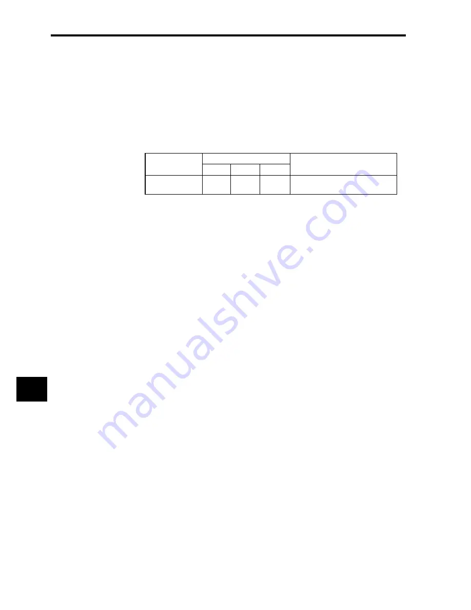
Alarm Display
Alarm Code Outputs
Description of Alarm
ALO1
ALO2
ALO3
A.CC
ON
OFF
ON
The multi-turn limit value is different
in the encoder and Servo Driver.
Summary of Contents for OMNUC W R88A-NCW152-DRT
Page 1: ...Cat No I538 E3 1 DeviceNet Option Unit OMNUC W Series Model R88A NCW152 DRT...
Page 53: ...4 Connectors 4 5 3 DeviceNet Network Configuration Restrictions 4 22 4...
Page 97: ...5 Parameter Settings 5 3 8 Notch Signal Output Positioning 5 44 5...
Page 211: ...8 Servo Driver Settings 8 5 3 Absolute Encoder Multi turn Limit Setting 8 24 8...
Page 257: ...9 Troubleshooting 9 46 9...


