8 Servo Driver Settings
8.2.1 Switching Servomotor Rotation Direction
8-8
8
8.2 Settings According to Equipment Characteristics
This section describes the procedure for setting parameters according to the dimensions and per-
formance of the equipment used.
8.2.1 Switching Servomotor Rotation Direction
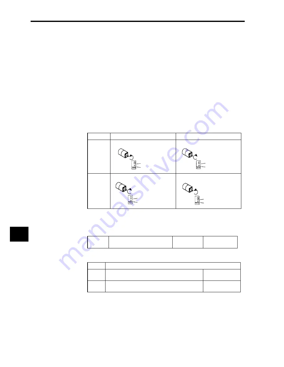
The Servo Driver has a Reverse Rotation Mode that reverses the direction of Servomotor
rotation without rewiring. Forward rotation in the standard setting is defined as counter-
clockwise as viewed from the motor output shaft.
With the Reverse Rotation Mode, the direction of Servomotor rotation can be reversed with-
out changing other items. The direction (+, -) of shaft motion is reversed. There are no other
changes.
Setting Reverse Rotation Mode
Use parameter Pn000.0.
Use the following settings to select the direction of Servomotor rotation.
Standard Setting
Reverse Rotation Mode
Forward
Command
Reverse
Command
Pn000.0
Reverse Rotation
Default Setting:
0
CCW rotation by
positive command
Setting
Description
0
Forward rotation is defined as counterclockwise (CCW)
rotation as viewed from the motor output shaft.
(Standard setting)
1
Forward rotation is defined as clockwise (CW) rotation as
viewed from the motor output shaft.
(Reverse Rotation
Mode)
Position data from
Servo Driver
Positive direction
CCW
Position data from
Servo Driver
Positive direction
CW
Position data from
Servo Driver
Negative direction
CW
Position data from
Servo Driver
Negative direction
CCW
Summary of Contents for OMNUC W R88A-NCW152-DRT
Page 1: ...Cat No I538 E3 1 DeviceNet Option Unit OMNUC W Series Model R88A NCW152 DRT...
Page 53: ...4 Connectors 4 5 3 DeviceNet Network Configuration Restrictions 4 22 4...
Page 97: ...5 Parameter Settings 5 3 8 Notch Signal Output Positioning 5 44 5...
Page 211: ...8 Servo Driver Settings 8 5 3 Absolute Encoder Multi turn Limit Setting 8 24 8...
Page 257: ...9 Troubleshooting 9 46 9...


