8.3 Settings According to Host Controller
8-13
8
8.3 Settings According to Host Controller
This section describes the procedure for connecting the Servo Driver to the host controller and
provides details on related parameters.
8.3.1 Sequence I/O Signals
Sequence I/O signals are used to control Servo Driver operation. Connect these signal termi-
nals as required.
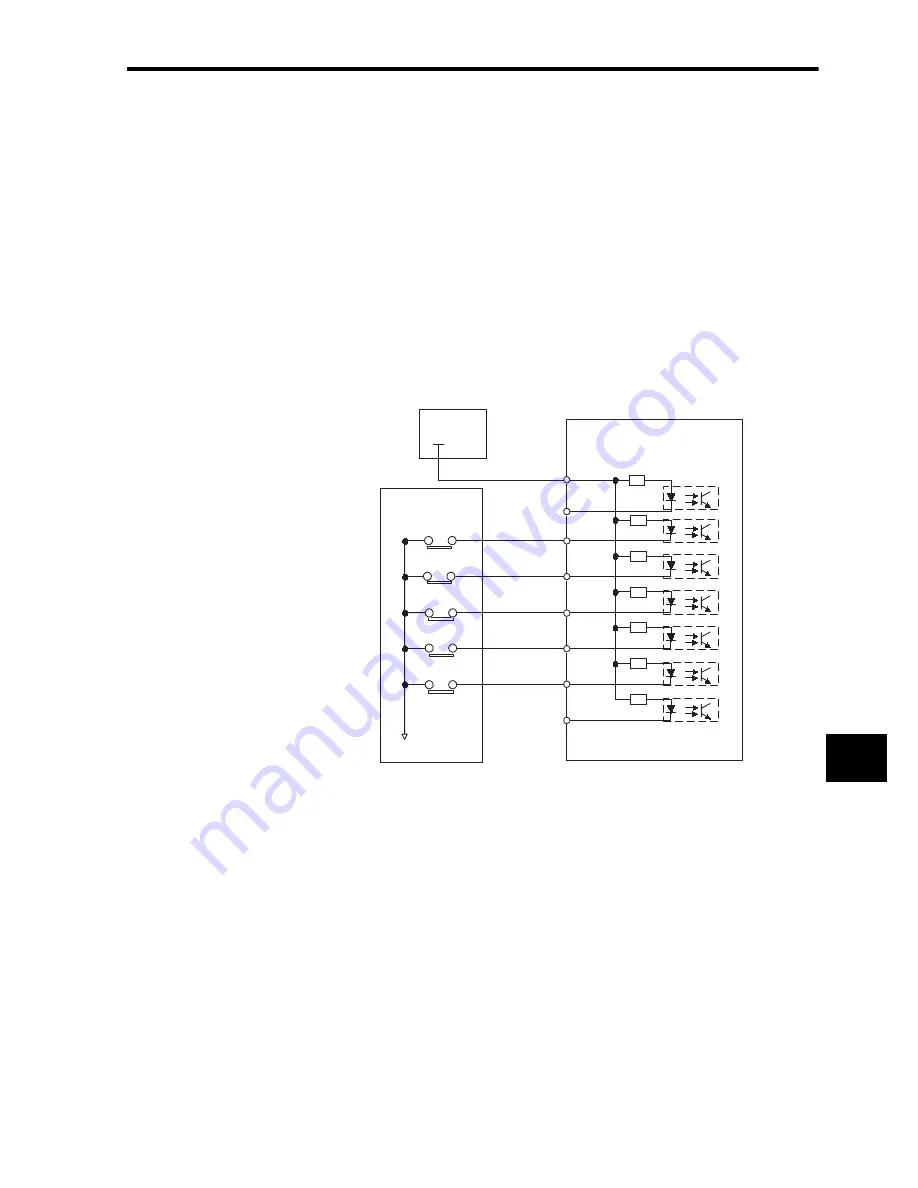
Input Signal Connections
Connect the sequence input signals as shown below (standard settings).
Note 1.
Provide an external 24-V power supply; the Servo Driver does not have an internal 24-V power
supply.
• Sequence input signal power supply specifications: 24 ± 1 V DC, 50 mA min.
2.
OMRON recommends using the same external power supply as that used for output circuits.
The allowable voltage range for the 24-V sequence input circuit power supply is +11 V to +25
V. Although a +12-V power supply can be used, contact faults can easily occur for relays and
other mechanical contacts under low currents. Confirm the characteristics of relays and other
mechanical contacts before using a 12-V power supply.
+24 V power
supply
+24VIN
CN1-47
POT
NOT
CN1-40
CN1-41
CN1-42
CN1-43
CN1-44
CN1-45
CN1-46
0 V
+24 V
Servo Driver
Photocoupler
3.3 k
Ω
Host controller
ORG
EXTP
ZERO
Summary of Contents for OMNUC W R88A-NCW152-DRT
Page 1: ...Cat No I538 E3 1 DeviceNet Option Unit OMNUC W Series Model R88A NCW152 DRT...
Page 53: ...4 Connectors 4 5 3 DeviceNet Network Configuration Restrictions 4 22 4...
Page 97: ...5 Parameter Settings 5 3 8 Notch Signal Output Positioning 5 44 5...
Page 211: ...8 Servo Driver Settings 8 5 3 Absolute Encoder Multi turn Limit Setting 8 24 8...
Page 257: ...9 Troubleshooting 9 46 9...


