8.6 How Do I Create a Smart Module Plan View?
Prerequisites
To create a smart module plan view, it is recommended that you obtain or draw
the planned layout of the smart modular data center before the creation.
Procedure
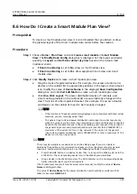
Step 1 Choose Home > Plan View and click Create smart module in Smart Module
View. The Modify Basic Config dialog box is displayed. Set the layout and device
quantity in Layout and Half-size cabinet qty./row based on the actual smart
module scenario.
●
If Room monitoring is set to No, draw a smart module view.
●
If Room monitoring is set to Yes, draw equipment room view and smart
module view.
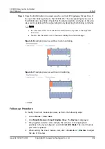
Step 2 Click Modify Device and create a smart module plan view.
●
Drag the icons of registered devices (for example, the access actuator) and
devices on the cabinet list to appropriate positions in the layout, click a device
icon, modify the value of Device Name in the displayed Basic Configuration
dialog box, and click Exit Edit Mode to create a smart module plan view.
●
Click One-Click Layout. The power distribution devices, IT cabinets, and
smart cooling products on the cabinet list are automatically arranged in the
view. The icons of other registered devices (for example, the access actuator)
and devices on the cabinet list need to be manually arranged.
NO TE
– If the locations of devices automatically deployed are inconsistent with their actual
locations, you can manually adjust them.
– The general input unit and power distribution unit support one-click layout only
when the versions are the same, ring networking is used, and cables are connected
based on the standard scenario in the corresponding user manual. If the version of
the general input unit and power distribution unit is earlier than V306B001D01, a
maximum of 20 devices can form a ring network. If the version of the general
input unit and power distribution unit is V306B001D01 or later, a maximum of 100
devices can form a ring network.
NO TE
There may be multiple same device icons on the editing page. If you are unable to
determine the positions of communications devices such as the access actuator, general
input unit, and power distribution unit, use the following methods to identify them:
●
Press the BLINK button on a device for less than 1s to report the blinking status to the
ECC800-Pro. The corresponding device icon in the WebUI plan view blinks.
●
Drag a device in the WebUI plan view. The RUN indicator on the corresponding device
blinks intermittently at super short intervals.
If both room-level and smart module access actuators exist, modify the value of Device
Name to distinguish them.
The value of Device Name for the power distribution unit should be consistent with its
label, for example, NMW A 01.
ECC800 Data Center Controller
User Manual
8 FAQ
Issue 04 (2021-10-09)
Copyright © Huawei Technologies Co., Ltd.
301

