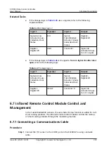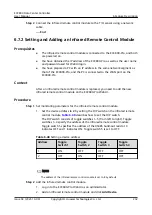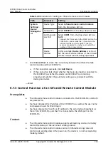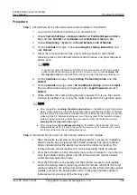
background image

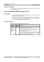
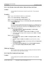
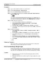
1. On the Linkage Group tab page, click the Link smoke alarm with skylight

open entry.

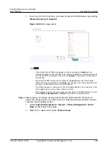
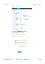
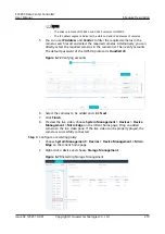
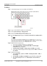
2. On the Linkage Logic List tab page, click Add.
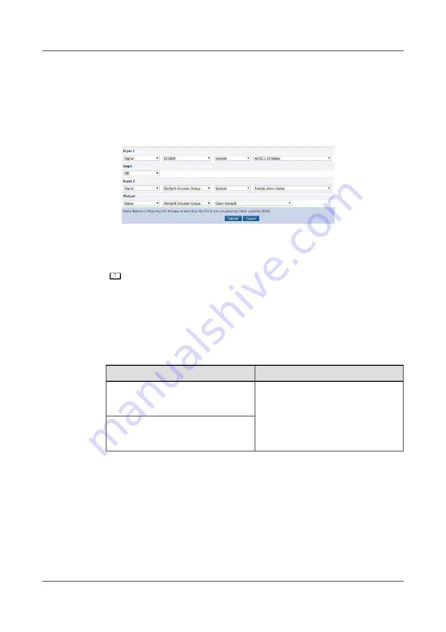
3. Set Linkage Logic List parameters for the Link smoke alarm with skylight

open.

Figure 6-80 Link smoke alarm with skylight open logic

4. Click Submit.

Step 11 Ensure that Link smoke alarm with skylight open on the Linkage Group tab

page is on.

NO TE

Click Link smoke alarm with skylight open on the Linkage Group tab page. If it is in on state,

the corresponding logic configurations on the Linkage Logic List tab page are available. If it is

in off state, the corresponding logic configurations on the Linkage Logic List tab page are

unavailable.

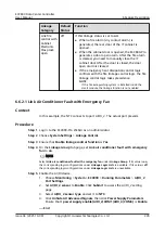
Step 12 Check the Link smoke alarm with skylight open linkage function.

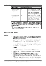
Table 6-42 Function commissioning

Check Method

Expected Result

When the skylight in the aisle is

closed, press the skylight button to

open the skylight.

● Smoke DI alarm is displayed on

the active alarm page of the app or

WebUI.

● The skylight is opened.

Simulate a smoky environment under

the smoke sensor or the multi-func

sensor.


----End

Follow-up Procedure

After Link smoke alarm with skylight open linkage is triggered and the alarm is

cleared, perform the following operations:

Press the reset button on the smoke sensor to clear the alarm.

Close the skylight manually.

ECC800 Data Center Controller

User Manual

6 Feature Description

Issue 04 (2021-10-09)

Copyright © Huawei Technologies Co., Ltd.

221

Summary of Contents for ECC800

Page 1: ...ECC800 Data Center Controller SmartDC V100R021C10 User Manual Issue 04 Date 2021 10 09 HUAWEI TECHNOLOGIES CO LTD ...

Page 2: ...cribed in this document may not be within the purchase scope or the usage scope Unless otherwise specified in the contract all statements information and recommendations in this document are provided AS IS without warranties guarantees or representations of any kind either express or implied The information in this document is subject to change without notice Every effort has been made in the prep...

Page 3: ...For details about the applicable ECC800 Pro functions see the FusionModule solution documentation The figures provided in this document are for reference only Intended Audience This document is intended for Sales engineers Technical support engineers Maintenance engineers Symbol Conventions The symbols that may be found in this document are defined as follows Symbol Description Indicates a hazard ...

Page 4: ...p Password Authentication for FusionModule500 800 Updated 5 2 Performing Startup Password Authentication for FusionModule500 800 Updated 6 4 2 Commissioning an Access Control Device and a Cabinet Electronic Lock or Fingerprint Lock Updated 6 5 3 3 Commissioning a C3220 Camera Updated 6 15 Setting Other Parameters and Channel Security Updated 6 14 1 3 Creating an ECC800 Pro on the NetEco Updated 6 ...

Page 5: ...Intelligent Inspection Updated 6 18 Numbering Management for Power Distribution Devices in the Power Module Updated 6 19 Intelligent Networking of FusionModule2000 Busways Updated 8 7 17 How Do I Set and Add an Electricity Meter 01 2021 01 06 This issue is used for first office application FOA ECC800 Data Center Controller User Manual About This Document Issue 04 2021 10 09 Copyright Huawei Techno...

Page 6: ... 3 2 1 UIM20A Expansion Module 26 3 2 2 Rack Environment Unit 29 3 2 3 Smart ETH Gateway 31 3 2 4 Access Control System 33 3 2 4 1 Aisle Access Control System 33 3 2 4 1 1 Access Actuator 34 3 2 4 1 2 Fingerprint and Card Reader with a Keypad 37 3 2 4 1 3 Fingerprint and Card Reader 38 3 2 4 1 4 Card Reader with a Keypad 40 3 2 4 1 5 Magnetic Lock 40 3 2 4 2 Cabinet Access Control System 41 3 2 4 ...

Page 7: ...l Module 75 3 2 21 Intelligent Battery Monitoring System 76 3 2 21 1 iBOX 77 3 2 21 2 iBAT 87 4 UI Description 90 4 1 WebUI 90 4 2 PAD App 97 5 Power On Commissioning 99 5 1 Preparations and WebUI Login 99 5 2 Performing Startup Password Authentication for FusionModule500 800 103 5 3 Commissioning Configuration Wizard 105 5 4 Configuring Event Notification 106 5 5 Commissioning the Smart Busbar 11...

Page 8: ...sioning a C3220 Camera 157 6 5 3 4 Commissioning a C3220 Camera SD Card Configured 166 6 5 4 Commissioning a Camera LAN Switch Networking Scenario 169 6 5 4 1 Commissioning an IPC6325 Camera 169 6 5 4 2 Commissioning an IPC6325 Camera SD Card Configured 174 6 5 4 3 Commissioning a C3220 Camera 177 6 5 4 4 Commissioning a C3220 Camera SD Card Configured 185 6 5 5 Commissioning the VCN 189 6 5 5 1 I...

Page 9: ... Space Manager Connected to a UIM20A Expansion Module 245 6 10 2 1 Determining the Position of the Smart U Space Manager 245 6 10 2 2 Querying the U Space Use Information 246 6 11 Power Management 247 6 11 1 Configuring Power Management Parameters 247 6 11 2 Setting Fault Isolation Parameters 250 6 11 3 Viewing the Power Usage 250 6 11 4 Viewing the Power Supply Links Diagram 251 6 12 Cooling Capa...

Page 10: ...UI Users 297 8 6 How Do I Create a Smart Module Plan View 301 8 7 How Can I Set and Add Devices 303 8 7 1 How Can I Set Integrated UPS Parameters Modbus TCP 303 8 7 2 How Can I Set and Add a UPS2000G A Modbus RTU 303 8 7 3 How Can I Set and Add a UPS2000G_L Modbus RTU 305 8 7 4 How Can I Set and Add a UPS5000 Modbus RTU 306 8 7 5 How Can I Set and Add a UPS5000 Modbus TCP 308 8 7 6 How Can I Set a...

Page 11: ...Water Sensor 344 8 7 34 How Can I Set and Add the Temperature Sensor Connected to the AI DI Port on the ECC800 Pro 345 8 7 35 How Can I Set and Add the Temperature Sensor Connected to the NTC Port on the Rack Environment Unit 346 8 7 36 How Can I Commission a Temperature Sensor Connected to the NTC Port on the T H Sensor 347 8 7 37 How Can I Set and Add a T H Sensor BOM Number 33010516 348 8 7 38 ...

Page 12: ...gh a UIM20A Expansion Module 376 8 33 How Can I Open Doors Remotely over the ECC800 Pro WebUI 377 8 34 How Can I Turn On or Off Aisle Lights in the Smart Module over the ECC800 Pro WebUI 378 8 35 How Can I Open Skylights Remotely over the ECC800 Pro WebUI 380 8 36 How Can I Turn On or Off Smart Cooling Products over the ECC800 Pro WebUI 381 8 37 How Can I Open the Cabinet Electronic Lock over the ...

Page 13: ...r the warranty Follow local laws and regulations when installing operating or maintaining the equipment The safety instructions in this document are only supplements to local laws and regulations Huawei will not be liable for any consequences of the following circumstances Operation beyond the conditions specified in this document Installation or use in environments which are not specified in rele...

Page 14: ...ures for installation operation and maintenance Before handling a conductor surface or terminal measure the contact point voltage and ensure that there is no risk of electric shock After installing the equipment remove idle packing materials such as cartons foam plastics and cable ties from the equipment area In the case of a fire immediately leave the building or the equipment area and turn on th...

Page 15: ... scratches caused during equipment transportation or installation in a timely manner Equipment with scratches cannot be exposed to an outdoor environment for a long period of time Before operations ensure that the equipment is firmly secured to the floor or other solid objects such as a wall or an installation rack Do not use water to clean electrical components inside or outside of a cabinet Do n...

Page 16: ...l equipment Professionals personnel who are trained or experienced in equipment operations and are clear of the sources and degree of various potential hazards in equipment installation operation maintenance Trained personnel personnel who are technically trained have required experience are aware of possible hazards on themselves in certain operations and are able to take protective measures to m...

Page 17: ...of AC powered facilities must be performed by qualified personnel Cabling When routing cables ensure that a distance of at least 30 mm exists between the cables and heat generating components or areas This prevents damage to the insulation layer of the cables Do not route cables behind the air intake and exhaust vents of the equipment Ensure that cables meet the VW 1 or ZB flame spread rating requ...

Page 18: ...ards with ESD packaging materials before storing or transporting them Figure 1 1 Wearing an ESD wrist strap Neutral Ground Voltage It is recommended that the three phase loads be equalized and the neutral ground voltage be kept at less than 2 V to meet power distribution requirements 1 4 Installation Environment Requirements To prevent fire due to high temperature ensure that the ventilation vents...

Page 19: ...working at heights Wear personal protective equipment such as the safety helmet and safety belt or waist rope and fasten it to a solid structure Do not mount it on an insecure moveable object or metal object with sharp edges Make sure that the hooks will not slide off Set a restricted area and eye catching signs for working at heights to warn away irrelevant personnel Carry the operation machinery...

Page 20: ...se wooden or fiberglass ladders when you need to perform live working at heights When a step ladder is used ensure that the pull ropes are secured and the ladder is held firm Before using a ladder check that it is intact and confirm its load bearing capacity Do not overload it Ensure that the ladder is securely positioned The recommended angle for a ladder against the floor is 75 degrees as shown ...

Page 21: ...mponents or cables inside Metal shavings from drilling may short circuit boards inside the equipment Obtain consent from the customer and contractor before drilling holes Wear goggles and protective gloves when drilling holes When drilling holes protect the equipment from shavings After drilling clean up any shavings that have accumulated inside or outside the equipment Moving Heavy Objects DANGER...

Page 22: ...ing transportation Move the cabinet with caution Any bumping or falling may damage the equipment 1 6 Others Exercise caution when shutting down the smart cooling product Doing so may cause equipment and room overheating which will damage the equipment Exercise caution when powering off the rPDU or PDU2000 Doing so may affect the power supply to equipment which will interrupt services Exercise caut...

Page 23: ...E bus providing rich bandwidth resources and high communication efficiency Supports remote upgrade fault data export and configuration parameter synchronization Eight access control devices and four cameras can be connected to a single smart module Cascades a maximum of three ECC800 Pros The active alarms and power usage effectiveness PUE data of cascaded ECC800 Pros can be displayed on the WebUI ...

Page 24: ...very and auto registration requiring no configuration This feature enables fast delivery and high maintainability Reliable Supports intelligent linkage management which allows customization of linkage logic implementing intelligent operation and maintenance Supports dual power inputs providing high reliability Supports intelligent battery monitoring and management to monitor the voltage and intern...

Page 25: ...anners Configuration 1 typical configuration one power module and one main control module Configuration 2 two power modules and one main control module NOTE In configuration 1 install a filler panel in slot 2 In configuration 2 install power modules in slots 1 and 2 Figure 3 1 ECC800 Pro collector in configuration 2 1 Slot 1 power modules 2 Slot 2 power modules 3 Slot 3 main control module ECC800 ...

Page 26: ...3 6 mm Weight 7 5 kg dual power supplies main control module Color Black Installation requirements Can be installed in a 1 U space in a standard 19 inch cabinet Environmental protection RoHS5 REACH WEEE Figure 3 2 ECC800 Pro rear view 1 53 5V DC_OUT1 2 53 5V DC_OUT2 3 AC_INPUT1 4 AC_INPUT2 Power Port The ECC800 Pro provides four power ports including two AC input ports AC_INPUT1 and AC_INPUT2 and ...

Page 27: ...tus indicator 3 AIDI_1 4 AIDI_2 5 COM1 AIDI_4 6 COM3 12V 7 WAN1 8 LAN1 POE 9 LAN2 POE 10 WAN2 11 COM4 CAN 12 COM2 AIDI_5 13 AIDI_3 14 DO 12V 15 RF_Z 802 15 4 16 WLAN reserved 17 4G 18 SW button NOTE The WLAN port is reserved and cannot be connected to a WLAN antenna for WLAN communication ECC800 Data Center Controller User Manual 3 Device Description Issue 04 2021 10 09 Copyright Huawei Technologi...

Page 28: ... Supports two WAN ports WAN1 is used to connect to the management system and WAN2 is used for maintenance The ports support autonegotiation of 10 100 1000 Mbit s communication rates Connect shielded network cables to the WAN ports LAN port Supports two LAN ports which can be connected to the LAN The ports support autonegotiation of 10 100 1000 Mbit s communication rates Connect shielded network ca...

Page 29: ... The power supply can be switched on or off and is on by default Fault isolation There are three groups of 12 V ports A group has a maximum current of 660 mA a route has a maximum current of 800 mA and the maximum total current is 2 A Group 1 AIDI_1 and DO 12V ports Group 2 AIDI_2 COM1 AIDI_4 and COM3 12V ports Group 3 AIDI_3 and COM2 AIDI_5 ports Wireless communicatio n Supports wireless communic...

Page 30: ... Due to the performance limitation of the wireless module China Telecom SIM cards are not supported USB Supports USB 2 0 and 5 V 1 A power supply After installing the WiFi module connect the WiFi module to the ECC800 Pro using the app on the PAD to view the basic information about the smart module such as layout resources energy efficiency environment and alarms You can insert a USB flash drive to...

Page 31: ...tions Ports The ECC800 Pro provides the following communications ports Figure 3 5 shows the pins of the RJ45 port Figure 3 5 RJ45 port pins There are four GE ports that is two WAN ports WAN1 and WAN2 and two LAN ports LAN1 POE and LAN2 POE Table 3 7 GE port pin definitions Item Description Pin sequence Pin 1 GE1 Pin 2 GE1 Pin 3 GE2 Pin 4 GE3 Pin 5 GE3 Pin 6 GE2 Pin 7 GE4 Pin 8 GE4 ECC800 Data Cent...

Page 32: ...485 Pin 5 RS485 Pin 6 DI Pin 7 DI Pin 8 GND Indicator Green indicator Power output indicator Steady on The 12 V DC output is normal Off No 12 V DC output is provided Table 3 9 COM3 12V port pin definitions Item Description Pin sequence Pin 1 RS485 Pin 2 RS485 Pin 3 12V DC_OUT Pin 4 RS485 Pin 5 RS485 Pin 6 Pin 7 Pin 8 GND ECC800 Data Center Controller User Manual 3 Device Description Issue 04 2021 ...

Page 33: ...s 1 2 4 and 5 identify sensor types Pin 3 and Pin 8 are power output ports Pin 6 and Pin 7 collect sensor data Pin 7 can detect current type sensors 4 20 mA Pin 6 and Pin 7 can detect the output status of passive dry contact type sensors Pin 3 and Pin 7 can detect temperature sensors Table 3 11 AIDI_1 AIDI_2 and AIDI_3 ports pin definitions Item Description Pin sequence Pin 1 Type_1 Pin 2 Type_2 P...

Page 34: ...n 1 Pin 2 Pin 3 12V DC_OUT Pin 4 Pin 5 Pin 6 DO_OUT Pin 7 DO_OUT Pin 8 GND Indicator Green indicator Power output indicator Steady on The 12 V DC output is normal Off No 12 V DC output is provided Table 3 13 USB port pin definitions Item Description Pin sequence Pin 1 5V Pin 2 DM Pin 3 DP Pin 4 GND ECC800 Data Center Controller User Manual 3 Device Description Issue 04 2021 10 09 Copyright Huawei ...

Page 35: ... is generated Off The system is normal RF_Z Green Communication status indicator Blinking at long intervals A network is set up and no node access is allowed the indicator blinks at 0 5 Hz on for 1s and then off for 1s Blinking at super short intervals A network is set up and node access is allowed the indicator blinks at 10 Hz on for 0 05s and then off for 0 05s SW Button Table 3 15 SW button des...

Page 36: ...ion Hold down for 1 minute Unavailable 3 1 3 Power Module Indicators Table 3 16 Power module indicator description Indicator Color Name Status Description Green Power indicator Steady on The module has input power Off The module has no input power or is faulty Blinking at long intervals The module is being queried the indicator blinks at 0 5 Hz on for 1s and then off for 1s Blinking at short inter...

Page 37: ...ervals The communication between the module and the outside is interrupted the indicator blinks at 0 5 Hz on for 1s and then off for 1s Red Fault indicator Steady on The module locks out due to output overvoltage The module has no output due to internal faults Off The module is normal 3 2 Southbound Device Introduction ECC800 Data Center Controller User Manual 3 Device Description Issue 04 2021 10...

Page 38: ...e UIM20A expansion module 1 DIP switch reserved 2 COM_OUT reserved 3 COM_IN reserved Table 3 17 Structural specifications of the UIM20A expansion module Item Specifications Width 120 mm Depth 200 mm Height 43 mm Operating temperature 30 C to 65 C ECC800 Data Center Controller User Manual 3 Device Description Issue 04 2021 10 09 Copyright Huawei Technologies Co Ltd 26 ...

Page 39: ...y The maximum output current is 900 mA when the voltage is 12 V COM1 AIDI_1 and COM2 AIDI_2 form a group COM3 AIDI_3 and COM4 AIDI_4 form a group COM5 AIDI_5 and COM6 AIDI_6 form a group and COM7 AIDI_7 and COM8 AIDI_8 form a group The 12 V DC power supply can be switched on or off and is on by default POE Connects to the ECC800 Pro through the PoE port E label 4 0 Supported Communications Ports T...

Page 40: ... 3 21 UIM20A indicators Indicator Status Description RUN Steady on A board application is being loaded Off The board is not running Blinking at long intervals The ECC800 Pro is successfully registered and the software runs properly blinking at long intervals 0 5 Hz on for 1s and then off for 1s Blinking at short intervals The communication is interrupted or the ECC800 Pro is unsuccessfully registe...

Page 41: ...ntervals for 0 5s and then off for 0 5s last 10s blinking at super short intervals for 10 Hz on for 0 05s and then off for 0 05s 3 2 2 Rack Environment Unit The rack environment unit collects and controls the environmental data of IT cabinets in the smart module Figure 3 8 Rack environment unit 1 Ground port 2 48 V DC power input port 3 PoE port 4 COM1 12V port 5 COM2 12V port 6 COM3 port 7 COM4 p...

Page 42: ...ts Temperatur e sensor port Provides two RJ45 ports to connect to six temperature sensors each RJ45 port connecting to three temperature sensors BLINK button Provides a BLINK function Indicators Table 3 24 lists the structural specifications for the rack environment unit Table 3 24 Indicator description Indica tor Col or Name Status Description PWR Gre en Power input status indicator Steady on The...

Page 43: ...t ETH gateway allows the extension of the 53 5 V DC power supply and FE communication for the ECC800 Pro and can be flexibly deployed in a smart module Figure 3 9 Smart ETH gateway 1 PWR_IN cascading power port 2 FE_1 cascading signal port 3 POE_1 2 ports 4 POE_3 4 ports 5 48V_OUT1 power output port 6 48V_OUT2 power output port 7 FE_2 cascading signal port 8 PWR_OUT cascading power port 9 BLINK bu...

Page 44: ...45 terminal with an indicator 10 100M communications rate complying with IEEE802 3 IEEE802 3u IEEE802 3af at BLINK button If you press the BLINK button the RUN indicator blinks intermittently at super short intervals blinking at super short intervals for 0 5s and then off for 0 5s for 5 seconds Indicators Table 3 26 Indicators on a smart ETH gateway Indicator Color Name Status Description PWR Gree...

Page 45: ...re access security Diverse access control devices such as the fingerprint and card reader with a keypad fingerprint and card reader and card reader with a keypad are supported Note that the communication distance between an access control device and an access actuator should be less than or equal to 5 meters NOTE If the IC cards used by the access control device need to be purchased the IC card ch...

Page 46: ... the magnetic lock by detecting the card swiping information of the card reader door open button information and fire linkage information It has access right management access event record and alarm record functions Figure 3 10 Access actuator 1 48 V power port 2 PoE port 3 RS485 port COM2 4 RS485 port COM1 5 Address DIP switch 6 Status indicator 7 BLINK button 8 WG_2 Wiegand interface 9 WG_1 Wieg...

Page 47: ...485 ports one route with the default communication rate of 9600 bit s physical port cascading supported reserved function Wiegand port Two Wiegand ports 12 V DC card reader operating power output two routes of card readers can operate at the same time BLINK button Press the button for less than 1 second to start blinking Hold down the button for 1 5 seconds to search for a network and start networ...

Page 48: ...n A system failure alarm is generated Off No system alarm is generated RF_Z Green Wireless communicati on status indicator Steady on No network parameters exist or a network is to be created Blinking at long intervals A network is set up and no node access is allowed the indicator blinks at 0 5 Hz on for 1s and then off for 1s Blinking intermittently at super short intervals The access actuator is...

Page 49: ... a fingerprint and card reader with a keypad Item Specifications Dimensions L x W x H 156 mm x 53 mm x 38 mm Rated operating voltage 12 V DC 15 Rated operating current 300 mA 15 Card type supported IC card Authorized storage A maximum of 3000 authorized users with a maximum of 6000 fingerprints Communications mode RS485 and Wiegand communications ports ECC800 Data Center Controller User Manual 3 D...

Page 50: ...unds three Authorized fingerprint collection LED indicator The indicator blinks blue red and blue in order Fingerprint reader The indicator turns on white Buzzer sounds The buzzer sounds once Card swiping LED indicator The indicator blinks blue red and blue in order Buzzer sounds The buzzer sounds once 3 2 4 1 3 Fingerprint and Card Reader Figure 3 12 Fingerprint and card reader 1 Fingerprint read...

Page 51: ...ndicator is steady blue Fingerprint reader The indicator is off Unauthorized fingerprint collection LED indicator The indicator blinks blue red blue red and blue in order Fingerprint reader The indicator turns on white Buzzer sounds The buzzer sounds three Authorized fingerprint collection LED indicator The indicator blinks blue red and blue in order Fingerprint reader The indicator turns on white...

Page 52: ...ting voltage range 10 8 13 2 V DC rated voltage 12 V DC Operating current Static standby current 80 mA dynamic operating current card swiping key pressing 150 mA minimum input current 12 V DC 300 mA Communication mode Wiegand communications port 3 2 4 1 5 Magnetic Lock Figure 3 14 Double door magnetic lock ECC800 Data Center Controller User Manual 3 Device Description Issue 04 2021 10 09 Copyright...

Page 53: ...Features An IC card can be used after being authorized using software An IC card can be authorized for one lock or all locks Door opening information is recorded through a network The system displays the status of cabinet doors and locks in real time the system displays the status of cabinet doors and locks in real time and reports the unauthorized door opening The system supports remote unlocking...

Page 54: ...unlock Supported Mechanical Code Lock Features The cabinet door can be opened with only the key and without the password The cabinet door can be opened with only the password and without the key The user can set a password A password should contain at least three digits The password can be reset if the user forgot it Figure 3 18 Mechanical code lock ECC800 Data Center Controller User Manual 3 Devi...

Page 55: ...igure 3 19 Cabinet electronic clasp lock 1 LED indicator 2 DIP switch 3 RJ45 power port Table 3 37 RJ45 port definitions No Pin Description Description 1 RS485 RS485 2 RS485 RS485 3 12 V power supply 12VDC 4 RS485 RS485 5 RS485 RS485 6 7 8 Ground GND ECC800 Data Center Controller User Manual 3 Device Description Issue 04 2021 10 09 Copyright Huawei Technologies Co Ltd 43 ...

Page 56: ...Stead y on A system failure alarm is generated Off The system is normal 3 2 5 Smart Module Actuator The smart module actuator is applied in a smart module It controls the lighting inside the smart module through the access control system host instructions infrared linkage information disabled by default or lighting button and provides a pad charging port The smart module actuator can also control ...

Page 57: ...ecifications Table 3 39 Indicators Item Specifications Power Input AC IN one AC input 90 V AC to 240 V AC 48 V DC input terminal with an input voltage of 36 V DC to 60 V DC Power output AC OUT1 two AC outputs 90 V AC to 240 V AC The maximum current of two outputs is 5 A AC OUT2 one AC output 90 V AC to 240 V AC The maximum current is 5 A LAN port FE communication with a communications rate of 10 1...

Page 58: ... ports use terminals DO 12V One DO port with 12 V DC power supply reserved AI DI port Five AI DI ports in which one is for detecting one door open button two for detecting lighting buttons and one for detecting fire extinguishing linkage signal One port is reserved Wiegand port Two Wiegand ports 12 V DC card reader operating power output two routes of card readers can operate at the same time BLIN...

Page 59: ... and then off for 0 125s Blinking The indicator blinks at super short intervals for 0 5s blinking at 10 Hz on for 0 05s and then off for 0 05s and then turns off for 0 5s The cycle lasts for 5s ALM Red Alarm indicator Steady on A system failure alarm is generated Off No system alarm is generated RF_Z Green Communicati on status indicator Steady on No network parameters exist or a network is to be ...

Page 60: ...ol the lighting inside the smart module by receiving commands from the access control system or host infrared linkage information disabled by default or signals from the light button It also provides a charging port for the PAD AC OUT2 Figure 3 21 AC actuator 1 AC OUT2 port 2 AC OUT1 port 3 AC IN port 4 Status indicator 5 BLINK button 6 AIDI_1 and AIDI_2 7 COM1 and COM2 ECC800 Data Center Controll...

Page 61: ... which can be set to 30 40 or 50 charging starts BLINK button Press the button for less than 1 second to start blinking Hold down the button for 1 5 seconds to search for a network and start networking Hold down the button for more than 10 seconds to clear network parameters Indicators Table 3 42 AC actuator indicators Indicator Color Name Status Description Power Green Power status indicator Stea...

Page 62: ...twork is to be created Blinking at long intervals A network is set up and no node access is allowed the indicator blinks at 0 5 Hz on for 1s and then off for 1s Blinking intermittent ly at super short intervals The AC actuator is searching for a network the indicator blinks at super short intervals for 0 5s and then turns off for 0 5s 3 2 7 Skylight Actuator The skylight actuator controls the rota...

Page 63: ...tage of 36 V DC 60 V DC PoE power supply one PoE port that complies with IEEE802 3at PoE port FE communication with the rate of 10 100 Mbit s Wireless communicatio n One wireless port that complies with IEEE 802 15 4 mutual backup with FE communication AI DI port Two AI DI ports for detecting fire extinguishing linkage signals smoke detection signals also supported DO output One 12 V DC power outp...

Page 64: ...us indicator Off The power is abnormal or the board program is loading Blinking at long intervals The skylight actuator successfully registers with the ECC800 Pro and the software runs properly the indicator blinks at 0 5 Hz on for 1s and then off for 1s Blinking at short intervals The communication fails or the skylight actuator fails to register with the ECC800 Pro the indicator blinks at 4 Hz o...

Page 65: ...tuator provides one DO port LOCK GND and one DI port BUTTON GND Table 3 45 lists the LOCK GND BUTTON GND port pin definitions Table 3 45 LOCK GND BUTTON GND port pin definitions Item Description LOCK GND pin sequence LOCK 12V_OUT GND GND BUTTON G ND pin sequence BUTTON DI3 GND GND 3 2 8 Multi Functional Sensor A multi functional sensor integrates the temperature and humidity T H sensor smoke senso...

Page 66: ...2 weak dust for each foot PoE port One PoE port that complies with IEEE802 3 at RS485 port Reserves one RS485 port DI input One DI input port 12 V DC power input BLINK button Wireless communication If the sensor is not connected to the network after you hold down the button for 2s to 3s the sensor connects to the network in RF_Z mode If the sensor is connected to network after you hold down the bu...

Page 67: ...ti functional sensor fails to register with the ECC800 Pro or the communication fails the indicator blinks at 4 Hz on for 0 125s and then off for 0 125s Blinking The indicator blinks at super short intervals for 0 5s blinking at 10 Hz on for 0 05s and then off for 0 05s and then turns off for 0 5s The cycle lasts for 10s ALM Red Alarm indicator Steady on A system failure alarm is generated Off No ...

Page 68: ...sor Item Specifications Operating voltage DC12 V 9 16 V DC Quiescent current 8 mA Alarm current 35 mA Output mode Relay output Output contact capacity 3 A 120 V AC or 3 A 24 V AC Operating temperature 10ºC to 50ºC Ambient humidity 95 RH non condensing Dimensions Diameter 112 mm height 41 mm 3 2 10 Temperature Sensor The temperature sensor BOM number 33010348 is used for the surface temperature mea...

Page 69: ...5 C Operating voltage 10 16 V DC Storage temperature 40 C to 70 C 3 2 11 Cabinet Temperature Sensor Figure 3 26 Cabinet temperature sensor Table 3 50 Technical specifications of a cabinet temperature sensor Item Specifications Temperature detection range 20 C to 70 C ECC800 Data Center Controller User Manual 3 Device Description Issue 04 2021 10 09 Copyright Huawei Technologies Co Ltd 57 ...

Page 70: ...generated in the micro modular equipment room the alarm beacon generates an audible signal and flashes to inform operators of fire and security risks Figure 3 27 Alarm beacon Table 3 51 Structural specifications of an alarm beacon Item Specifications Dimensions L x W x H 130 mm x 75 mm x 55 mm Installation requirements Installed on a wall Environmental protection RoHS Reach ECC800 Data Center Cont...

Page 71: ...strip of the smart U space manager and the main control box must be assembled together Otherwise the physical location of devices cannot be detected Figure 3 28 Smart U space manager 1 Asset detection strip 2 Asset label 3 Main control box Table 3 53 Technical specifications of the smart U space manager Item Specifications Characteristic Applicable to 42 U cabinets Communications port RS485 Modbus...

Page 72: ...le raises a critical alarm Blinking for 3 seconds Access authorization fails and the aisle door cannot be opened Blinking The eLight fails to communicate with the ECC800 Pro Orange light Steady on The smart module raises a major alarm Yellow light Steady on The smart module raises a minor alarm Gray light Steady on The smart module raises a warning Green light Blinking for 3 seconds Access authori...

Page 73: ...ion requirements Install on a guide rail Operating temperature 4 C 40 C Ambient humidity 5 95 RH non condensing 3 2 15 Water Sensor A water sensor detects water on the floor in real time and generates an alarm when water is detected 3 2 15 1 WLDS600 Water Sensor The WLDS600 water sensor consists of a water detection cable a water detector with the BOM number of 33010556 an extension line and a con...

Page 74: ...DC or 9 16 V AC Impulse current 450 mA Power dissipation 2 W Power communicatio n connector RJ45 female connector 1 piece Protocol type Modbus RTU data bits 8 bits no parity Baud rate address Default support 9600 baud rate configurable address configurable default address is 1 stop bit is 1 bit Detected distant 100 m support cable connection in series ECC800 Data Center Controller User Manual 3 De...

Page 75: ...N track install supported 3 2 15 2 WLDS900 Water Sensor The WLDS900 water sensor with the BOM number of 33010352 consists of a water detection cable a water detector and a conversion cable Figure 3 31 WLDS900 water sensor 1 Water detector 2 Conversion cable end A connected to the water detector 3 Conversion cable 4 Conversion cable end B connected to the water detection cable 5 Water detection cab...

Page 76: ... of 33010444 contains electrode probes and cables Figure 3 32 Electrode water sensor Table 3 58 Technical specifications of the electrode water sensor Item Specification Operating temperature 40 C to 80 C Storage temperature 40 C to 80 C Service life 10 years 3 2 16 WiFi Module The WiFi module provides WiFi signals for equipment such as PADs to interact with the host computer ECC800 Data Center Co...

Page 77: ...835 GHz Wireless transmission power 20 dBm MAX EIRP Supported operating system Windows 2000 XP Vista Linux Win 7 Port USB 2 0 Hi Speed connector Voltage range 5 0 V DC 5 Operating temperature 20 C to 70 C Storage temperature 40 C to 90 C Relative humidity 10 90 RH non condensing Storage humidity 5 90 RH non condensing Power 0 8 W ECC800 Data Center Controller User Manual 3 Device Description Issue...

Page 78: ...ge of 36 V DC 60 V DC PoE power supply one PoE port 10 100M communication rate complying with IEEE802 3at RS485 CA N Provides RS485 CAN ports The default communications rate for the RS485 port is 9600 bit s and that for the CAN port is 125 kbit s Both ports match the RJ45 terminal shared by RS485 and CAN BLINK button If you press the BLINK button the RUN indicator blinks intermittently at super sh...

Page 79: ...ls to register with the ECC800 Pro the indicator blinks at 4 Hz on for 0 125s and then off for 0 125s Blinking The indicator blinks at super short intervals for 0 5s blinking at 10 Hz on for 0 05s and then off for 0 05s and then turns off for 0 5s The cycle lasts for 10s ALM Red Alarm indicator Steady on A system failure alarm is generated Off No system alarm is generated 3 2 18 PAD The PAD allows...

Page 80: ...reen 10 1 inch 1920 x 1200 resolution IPS screen and multi touch Storage Machine 32 GB Memory 3 GB Extension card Micro SD a maximum of 256 GB non standard configuration Button Port Touch button power switch and volume button 3 5 mm stereo headphones port Micro SD card port MicroUSB port ECC800 Data Center Controller User Manual 3 Device Description Issue 04 2021 10 09 Copyright Huawei Technologie...

Page 81: ...mera up to 8 M 3264 x 2448 pixels front camera up to 1 9 M 1600x1200 pixels Battery Materials Li polymer Capacity 5100 mAh typical value or 4980 mAh rated value WiFi connection web page browse time about 6 5 hours Power adapter charge time about 3 5 hours 5 V 2 A adapter 3 2 19 T H Sensor 3 2 19 1 T H Sensor BOM Number 33010346 Figure 3 36 Appearance The T H sensor uses an RJ45 connector ECC800 Da...

Page 82: ...Specifications Temperature measuring range 20 C to 70 C Temperature accuracy 1 C Humidity measuring range 5 95 RH Humidity precision 5 RH 25 C 20 80 RH Operating temperature 20 C to 70 C Operating voltage 9 16 V DC Storage temperature 40 C to 70 C Output RS485 ECC800 Data Center Controller User Manual 3 Device Description Issue 04 2021 10 09 Copyright Huawei Technologies Co Ltd 70 ...

Page 83: ...ector Table 3 66 RJ11 port pin definitions Pin Description Pin1 or Pin 2 GND Pin3 RS485 Pin4 RS485 Pin5 or Pin 6 12V Table 3 67 T H sensor specifications Item Specifications Temperature measuring range 20 C to 70 C Temperature accuracy 1 C Humidity measuring range 5 95 RH Humidity precision 5 RH 25 C 20 80 RH ECC800 Data Center Controller User Manual 3 Device Description Issue 04 2021 10 09 Copyri...

Page 84: ...Appearance The T H sensor uses an RJ45 connector NOTE The appearance of the T H sensor depends on the onsite delivery Figure 3 41 Pins of an RJ45 connector Table 3 68 RJ45 port pin definitions Pin Description Pin1 or Pin 4 A Pin2 or Pin 5 B Pin3 V Pin6 V Pin7 Reserved ECC800 Data Center Controller User Manual 3 Device Description Issue 04 2021 10 09 Copyright Huawei Technologies Co Ltd 72 ...

Page 85: ...25 C 20 80 RH Operating temperature 20 C to 70 C Operating voltage 9 16 V DC Storage temperature 40 C to 70 C Output RS485 3 2 19 4 T H Sensor BOM Number 02311FQG Figure 3 42 Appearance 1 RS485 OUT 2 RS485 IN 3 DIP switch 4 Button 5 NTC1 3 6 NTC4 6 7 Display ECC800 Data Center Controller User Manual 3 Device Description Issue 04 2021 10 09 Copyright Huawei Technologies Co Ltd 73 ...

Page 86: ...25 C 20 80 RH Operating temperature 20 C to 70 C Operating voltage 9 16 V DC Storage temperature 40 C to 70 C Output RS485 3 2 19 5 T H Sensor BOM Number 02312PBL Figure 3 43 Appearance 1 RS485 OUT 2 RS485 IN 3 DIP switch 4 Button 5 NTC1 3 6 NTC4 6 7 Display ECC800 Data Center Controller User Manual 3 Device Description Issue 04 2021 10 09 Copyright Huawei Technologies Co Ltd 74 ...

Page 87: ...0 C Output RS485 3 2 20 Infrared Remote Control Module Figure 3 44 Infrared remote control module Table 3 72 Technical specifications of the infrared remote control module Item Specifications Number of supported remote control commands 4 Communication Interworks with the monitoring system over Modbus RTU to implement remote control The baud rate can be 9600 bit s ECC800 Data Center Controller User...

Page 88: ...OH of batteries and battery strings and estimates the battery health status accordingly supports battery tripping management and uploads data to the management unit through COM or PoE ports The iBAT is a battery monitoring module that monitors the voltages internal resistances and pole temperatures of batteries In the scenario with battery cabinets the iBOX is installed inside a smart module batte...

Page 89: ...battery status data from the downstream iBAT groups through wireless communication and sends the data to the ECC800 Pro UPS and the third party network management system NMS through COM or PoE ports ECC800 Data Center Controller User Manual 3 Device Description Issue 04 2021 10 09 Copyright Huawei Technologies Co Ltd 77 ...

Page 90: ... BCB_4 ports BCB_2 BCB_4 reserved 9 BCB_OUT and BCB_IN ports 10 Networking switch 11 PWR indicator 12 RUN indicator 13 ALM indicator 14 RF_Z indicator 15 Delivered antenna Figure 3 47 iBOX bottom view 1 Fastener 2 Micro SD card slot 3 Default button IP reset 4 ADDR dual in line package DIP switch RS485 communications address ECC800 Data Center Controller User Manual 3 Device Description Issue 04 2...

Page 91: ...wer module is adopted to supply 12 V DC operating voltage 2 Table 3 74 48 V 0 5 A port pin definitions Pin Definition Description 1 The system provides 48 V DC operating voltage in this scenario 2 PoE Port Figure 3 49 PoE port pins ECC800 Data Center Controller User Manual 3 Device Description Issue 04 2021 10 09 Copyright Huawei Technologies Co Ltd 79 ...

Page 92: ...ndicator 2 TX 3 RX 4 5 P45_P1 6 RX 7 8 P78_P1 COM Port Figure 3 50 COM port pins Table 3 76 COM port pin definitions Pin Signal Description 1 RS485 Two cascaded RS485 communication ports 2 RS485 3 NC 4 RS485 5 RS485 6 GND 7 NC 8 NC ECC800 Data Center Controller User Manual 3 Device Description Issue 04 2021 10 09 Copyright Huawei Technologies Co Ltd 80 ...

Page 93: ...ct output signal Open The dry contact output is open Closed The dry contact output is closed Open 4 COM HALL Current Monitoring Port Figure 3 51 HALL current monitoring port pins Table 3 78 Pin definitions for HALL current monitoring ports Pin Definition Description 1 12V Detect the charge and discharge currents of four battery strings or eight battery routes 2 12V 3 AI 4 GND ECC800 Data Center Co...

Page 94: ...sor is not enough use multiple Hall effect sensors to monitor the current of one battery string The iBOX supports the sum of the monitoring results of multiple Hall effect sensors which is set through Multi Hall cur setting The value of Multi Hall cur setting equals the number of positive or negative Hall effect sensors in a single battery string and should be greater than or equal to 1 BCB Port F...

Page 95: ...Descripti on 1 OL Specifies whether the BCB connects to the signal output port Specifies whether the cascaded BCBs connect to the signal input port Grounded BCB connected Disconnect ed BCB not connected Disconne cted Receives BCB comman ds sent by the UPS and supports BCB port cascadin g manage ment 2 STA Signal output port for the battery circuit breaker status Monitors whether the cascaded BCBs ...

Page 96: ...Secondary side ground DIP Switch Table 3 81 DIP switch description No Definition Description 1 ADDR_1 RS485 communications address setting 2 ADDR_2 3 ADDR_3 4 ADDR_4 Indicators Table 3 82 Indicators Indicat ors Color Meaning Status Description Measure RF_Z Green Wireless communi cation status Steady on No network parameters exist A network is to be created Requires no handling ECC800 Data Center C...

Page 97: ...termitte ntly at super short intervals Blinking lasting for 10s Requires no handling Blinking at short intervals Communica tion fails No legitimate northbound data has been received for 3 minutes 1 Check whether the communication cable is loose If yes reconnect the communication cable If no go to the next step 2 Check whether the device is malfunctioning If yes replace the device If no contact the...

Page 98: ...that is on for 0 125s and then off for 0 125s If an indicator blinks at super short intervals it is blinking at 10 Hz that is on for 0 05s and then off for 0 05s Blinking intermittently at short intervals means an indicator blinks at super short intervals for 0 5s and then remains off for 0 5s Networking Switch Table 3 83 Networking switch description Name Definition Function Button pressing Press...

Page 99: ...0 10 3 2 21 2 iBAT The iBAT is a battery monitoring module that monitors the voltages internal resistances and pole temperatures of batteries and supports 12 V power Features Monitors the voltages internal resistances and pole temperatures of batteries Supports the hibernation function When it detects that the battery voltage is low it will enter the low power mode Communicates with the iBOX wirel...

Page 100: ...tervals The networking succeeds Alarm Red ALM Off The iBAT is not faulty Steady on The iBAT is faulty Communication with the iBOX times out No network is connected The iBAT is waiting to connect to a network Blinking at super short intervals iBattery 2 0 Network parameters are being cleared The iBAT is blinking Blinking at short intervals iBattery 3 0 ECC800 Data Center Controller User Manual 3 De...

Page 101: ...s Networking Switch Table 3 86 Networking switch description Name Definition Function Button pressing Press the button for less than 5 seconds Searches for and joins a network if there is no network Initializes the network parameters if there is a network Button holding down Hold down the button for more than 5s Clears the current network and resets the wireless module disconnects the network ECC8...

Page 102: ...bUI For data transmission security the ECC800 Pro supports WebUI access through TLS Figure 4 1 Home page ECC800 Data Center Controller User Manual 4 UI Description Issue 04 2021 10 09 Copyright Huawei Technologies Co Ltd 90 ...

Page 103: ...l strength Yes This menu is displayed only when Mobile data control under System Settings System Parameters is set to Enable Mo nito ring System Connected devices such as ECC800 Pro ETH Converter Group and Smart ETH Gateway Group Monitor the device running information in real time set device running parameters and control the device running For example set smart cooling product parameters delete d...

Page 104: ... Sensor Group Access Actuator Group and Skylight Actuator Group Yes Cooling Connected smart cooling products Yes Cabinet IT cabinet Yes Qu ery Historical Alarms Query historical alarms No Performance Data Query device performance data No Operation Log Query operation logs No Access Event Query access control events No Export Data Export historical data and device data No ECC800 Data Center Control...

Page 105: ... IP for WAN_1 is 192 168 8 10 by default The default IP addresses of Primary DNS server and Secondary DNS server in the DNS Server Address area are 192 168 8 10 IP for WAN_2 is 192 168 0 10 by default Time Set the time zone time and date No Mobile Data Set mobile data parameters Yes Access Managemen t Set the access users and permissions No Video Managemen t Add modify or delete videos Yes NMS App...

Page 106: ...e security certificate for device access No Security Certification Change No Smart Module Cascading Cascade up to three ECC800 Pros through multi module configuration Yes PUE Configuratio n Set PUE parameters Yes PUE Function is Enable by default PUE configuration mode is Standard by default Linkage Control Set linkage control rules Yes Alarm Parameters Basic Alarm Parameters Set basic alarm param...

Page 107: ... addresses in the whitelist are allowed to access the ECC WebUI Predictive Maintenance Model Management List View AI model information No Predictive Maintenance is involved only in the ECC800 Pro equipped with an AI chip Mai nte nan ce Software Upgrade Software Upgrade Upgrade the software of the ECC800 Pro and its southbound devices online Yes Version Information Query the device version and acce...

Page 108: ...he QR code No Parameter Sync Synchronize device parameters to quickly import data of southbound devices such as the multi functional sensor and skylight actuator Support device replacemente No Access Package Mgmt View access package information No Configuratio n Wizardd Support the deployment wizard and set simple parameters as instructed by the wizard No Life Cycle Check the service life of main ...

Page 109: ...e Cascading d If the system type is FusionModule2000 or FusionModule5000 this function is unavailable e This function is supported only by some devices such as Huawei smart cooling products and integrated UPSs 4 2 PAD App Figure 4 2 Home screen Table 4 2 App functions Screen Function Home Allows you to view the layout information of the smart module as well as the overview of resources energy effi...

Page 110: ... to modify the names and positions of devices in the device layout diagram and deliver a blinking command to a device under iFind Export Data Allows you to export device configuration data current configuration files and historical data Import Data Allows you to import a configuration file Performa nce Data Allows you to view device performance data such as the battery curve and battery discharge ...

Page 111: ...lling or replacing the device or ECC800 Pro set monitoring parameters and add the device 5 1 Preparations and WebUI Login Prerequisites Supported operating system Windows 7 and later versions It is recommended that the screen resolution be 1366 x 768 or higher Browser Chrome Firefox 32 Internet Explorer 11 or later Procedure Step 1 Connect a network cable between the PC network port and the WAN1 p...

Page 112: ...0 and default gateway is 192 168 8 1 set the PC IP address to 192 168 8 12 subnet mask to 255 255 255 0 and default gateway to 192 168 8 1 Step 3 Set LAN parameters NOTE If the ECC800 Pro connects to a LAN and a proxy server has been selected perform Step 3 3 and Step 3 4 If the ECC800 Pro connects to the Internet and the PC in a LAN accesses the Internet over a proxy server do not perform Step 3 ...

Page 113: ... list of trusted sites Figure 5 1 Adding an address 3 Enable file download and set the security level of the trusted site to low Figure 5 2 Setting parameters ECC800 Data Center Controller User Manual 5 Power On Commissioning Issue 04 2021 10 09 Copyright Huawei Technologies Co Ltd 101 ...

Page 114: ...preset password Changeme set the language and click Log In NOTE After the first login change the password in time to ensure account security and prevent unauthorized network attacks such as data tampering The Company will not be liable for any security issues caused by your failure to change the preset password in time or password loss after changing Change the password of the user account periodi...

Page 115: ...Password dialog box 3 Within 24 hours inform the technical support of Barcode and Verify Code to obtain the password After obtaining the password enter the password in the Password text box and click Submit to complete the authentication of the startup password NOTE The verification code is valid for 24 hours by default After the validity period expires the verification code is automatically updat...

Page 116: ...tion on the WebUI there is no preset password After WiFi is enabled by pressing the button the mobile phone prompts the customer to change the default password when logging in to the app After you disable the WiFi hotspot function on the WebUI and press the button again the WiFi function is still enabled In this case the WiFi password is the one you changed last time The WiFi function is disabled ...

Page 117: ... for the following functions Smart Module Settings Basic Param Settings Add Devices Add Sensor Plan View Power Dist Settings Temp Control Settings Linkage Test Video Settings and Access Management Procedure Step 1 Log in to the ECC800 Pro WebUI as an administrator NOTE The configuration wizard is displayed when you log in to the ECC800 Pro WebUI for the first time or the system type is switched St...

Page 118: ...p 1 Choose System Settings Event Notification Step 2 Set related outbox parameters 1 Set related parameters in the Outbox Settings area on the Mailbox Settings page If the address type of the outbox is Domain name choose System Settings System Parameters and set related parameters in the DNS Server Address area on the Monitor IP page NOTE The DNS server address is provided by the local network ope...

Page 119: ...ame at the position of the blinking cursor and press Enter to obtain email server IP addresses Non encryption 25 The email server must comply with the standard SMTP protocol to ensure that the email sending and receiving functions are normal Enter the email client authorizatio n password at Password for 163 Mail 126 Mail and QQ Mail 163 Mail smtp 163 com Non encryption 25 SSL encryption 465 126 Ma...

Page 120: ... is not used for other purposes The address is encrypted during transmission in the ECC800 Pro to ensure that the personal data of users is fully protected Figure 5 5 Adding an email address to receive emails NOTE Click Test to check whether the added mailbox is available If it is available Successfully to send the test email is displayed If it is unavailable Failed to send the test email is displ...

Page 121: ...g a mobile number NOTE Click Test to check whether the added mobile phone number is available If it is available Successfully to send the test short message is displayed If it is unavailable Failed to send the test short message is displayed Check whether the mobile phone number is correctly set Step 5 Set the alarm notification delay parameter and the new alarm notification parameter ECC800 Data ...

Page 122: ...TICE Mailbox Address in Alarm Notification can be selected after it is added in Mailbox Settings Mobile Phone Number can be selected after it is added in SMS Settings ECC800 Data Center Controller User Manual 5 Power On Commissioning Issue 04 2021 10 09 Copyright Huawei Technologies Co Ltd 110 ...

Page 123: ...e and the DNS server is normal 3 1 Try again later 2 Check whether the domain name of the email server is correctly configured 5 Check whether the IP address corresponding to the domain name of the email server is configured 11 1 Check whether the IP address of the DNS server is correct 2 Check whether the domain name of the email server is correctly configured Failed to connect to the email serve...

Page 124: ...ort the CA certificate that matches the email server certificate 2 Check the validity period of the certificate and replace it with a valid CA certificate 3 Provide monitoring run logs and contact the service center Failed to send the test email 504 Check whether the outbox address matches the user name for logging in to the email server 535 1 Log in to the email box of the email sender and start ...

Page 125: ...gs and contact the service center to reduce the email sending frequency 534 Log in to the sender s mailbox client and enable the access to the insecure applications 5 5 Commissioning the Smart Busbar Context In the smart busbar scenario general input units and power distribution units communicate with the ECC800 Pro using the Modbus MAC protocol After the general input units and power distribution...

Page 126: ...n actual conditions For example if Rated system current is 250 A set System CT ratio to 250 Upper load current threshold 80 When the load current exceeds the preset value an alarm is generated Lower load current threshold 60 When the load current is lower than the preset value an alarm is generated 2 Set the parameters for other general input units in the same way or by synchronizing parameters Pa...

Page 127: ...r each branch QF1 Branch circuit breaker in use L1 QF2 Branch circuit breaker in use L2 Enable When the parameter is set to Disable for a branch all alarms of the branch will not be reported When the parameter is set to Enable for a branch all alarms of the branch will be reported Upper load current threshold 80 When the load current exceeds the preset value an alarm is generated Lower load curren...

Page 128: ...oning Check Method Normal Connection Status Choose Maintenance Configuration Wizard Linkage Test eLight Actuator Commissioning and click Test The eLight is lit up in red green blue and white in sequence for 3 seconds respectively and then turns off Step 3 Set eLight parameters 1 Log in to the ECC800 Pro WebUI as an administrator 2 In the Smart Module View click Modify Device Select an eLight actua...

Page 129: ... actuator in the smart module view If there are one access actuator and two eLight actuators in an aisle the access actuator is automatically associated with the two eLight actuators End Follow up Procedure To modify the parameters of a single eLight do as follows 1 Choose Monitoring Aisle eLight Actuator Group eLight Actuator The Running Parameters page is displayed 2 Select the Associated alarm ...

Page 130: ... The eLight strip light is steady blue atmosphere light NOTE After you set the alarm severity the eLight indicator is off if no alarm is generated 5 7 Commissioning the eLight for FusionModule500 800 When the system type is FusionModule500 800 and an eLight is installed perform the following steps to configure it Procedure Step 1 Ensure that the device address of the eLight actuator is the default...

Page 131: ...Address Set the device address for the eLight actuator based on the actual situation 3 Click Test Connect to check whether the eLight Actuator connects properly If the connection succeeds click Confirm The connected devices are displayed in the Number of connected devices list If the connection fails check whether the cable is properly connected to the device whether the device is running properly...

Page 132: ... you set the alarm severity the eLight indicator is off if no alarm is generated 4 Optional When the eLight is connected to a cabinet commission the cabinet light When you open the front door of the cabinet the tube light connected at the front door turns white When you open the rear door of the cabinet the tube light connected at the rear door turns white When the front or rear door of the cabine...

Page 133: ...tarts with 21 and is attached to the device Procedure Step 1 Set the PDU2000 monitoring parameters Set the PDU2000 M C monitoring parameters NOTE The display of a single phase module is used as an example After the PDU2000 M C is powered on the LCM displays the initialization screen Figure 5 10 PDU2000 M C initialization screen Press MENU to enter the device communications address screen Figure 5 ...

Page 134: ...address screen Figure 5 12 PDU2000 M H communications settings Press DOWN and UP to select the address to be set Press MENU to confirm the settings NOTE If modification is successful is displayed If modification fails is displayed Step 2 Add a PDU2000 1 Log in to the ECC800 Pro WebUI as an administrator 2 Add a PDU2000 NOTE The PDU2000s whose addresses range from 1 to 20 can be automatically ident...

Page 135: ...are consistent with the device parameters End 5 9 Commissioning Cabinet Electronic Clasp Locks If a cabinet electronic clasp lock is installed perform the following steps to configure it Prerequisites COM1 COM3 on the ECC800 Pro are connected to cabinet electronic clasp locks The smart module view has been deployed The layout type is single row view The cabinet door can be opened and closed proper...

Page 136: ...nected in series Set a device address for a cabinet electronic clasp lock by operating the DIP switch on the cabinet electronic clasp lock Toggle switches 1 to 6 specify the device address in binary mode ON indicates 1 and OFF indicates 0 Table 5 16 Setting device addresses Address Toggle Switch 1 Toggle Switch 2 Toggle Switch 3 Toggle Switch 4 Toggle Switch 5 Toggle Switch 6 1 ON OFF OFF OFF OFF ...

Page 137: ... ECC800 Pro are running properly and whether the parameter settings are consistent with the device parameters 5 Connect the electronic clasp locks of other cabinets Step 5 Commission the cabinet electronic clasp locks Table 5 18 Function check Function Path Operation View cabinet electroni c clasp lock informati on Choose Monitoring Cabinet IT Cabinet101 E LOCK1 a Click the Running Info tab View t...

Page 138: ...oors from the Open the door drop down list box select the setting and click Submit The cabinet electronic clasp locks unlock the doors in batches based on the signal value a Cabinet electronic clasp lock 1 of IT cabinet 101 is used as an example End ECC800 Data Center Controller User Manual 5 Power On Commissioning Issue 04 2021 10 09 Copyright Huawei Technologies Co Ltd 126 ...

Page 139: ...lecting Data refer to the following procedure Procedure Step 1 Choose System Settings Performance Parameters The Performance Parameters page is displayed Step 2 Click the Performance Parameters enable tab select a device in Device Type and click OK All enabled performance indicators are displayed in the result list Step 3 You can set the status of enabled performance indicators to Disable as requi...

Page 140: ...e parameters of the device End 6 2 Setting ECC800 Pro Cascading If multiple smart modules 3 are installed in the same room and the customer has not deployed the NetEco multiple ECC800 Pros can be cascaded for management To set the cascading function follow the procedure in this section Prerequisites Cascaded ECC800 Pros communicate with each other properly Context A maximum of three ECC800 Pros ca...

Page 141: ...click Confirm Step 8 Optional Click Link in a smart module on the cascading page to access the corresponding ECC800 Pro login page Step 9 Optional Filter and query the details of each alarm by smart module device or alarm severity in the Active alarms area End 6 3 Commissioning a UIM20A Expansion Module Context Devices connected through the UIM20A expansion module UIM for short can be automaticall...

Page 142: ...splayed dialog box for binding IT cabinets and devices click Auto Bind to bind devices Automatic binding is supported in one to one and one to four scenarios One to one scenario Each cabinet corresponds to a UIM Each cabinet contains two or more types of intelligent components which can be the rPDU MPDU rPDU PN rPDU PDU2000 M C PDU2000 M H smart U space manager cabinet electronic lock fingerprint ...

Page 143: ... T H sensors to be cascaded The addresses of the T H sensors connected to the same COM port must be different Addresses 1 to 8 are supported The addresses of T H sensors connected to different COM ports can be the same In actual configuration bind sensors to the corresponding cabinets in sequence Each cabinet can connect to only one T H sensor a T H sensor is automatically bound to the cabinet aft...

Page 144: ...et that houses the UIM through indicator blinking Then you can change the IT cabinet name Figure 6 2 Device blinking Step 8 Optional Click change the IT cabinet name change the UIM and the devices connected to the COM ports of the UIM20A and click in the Operation column Step 9 Optional Click to delete a device binding relationship Step 10 Choose Home Plan View on the ECC800 Pro WebUI and drag the...

Page 145: ... AI_DI 1 1 Log in to the ECC800 Pro WebUI as an administrator 2 Choose System Settings Signal Name Modify The Batch Signal Configuration page is displayed 3 Set Device Type to Independent Deployment AI_DI Unit set Device Name to Independent Deployment AI_DI1 Unit and click OK 4 On the query result tab page set the new signal name of AI DI_1 to Door1 and click Submit NOTE Order number of door senso...

Page 146: ...ning Parameters set the door status sensor parameters Table 6 6 Parameter settings Setting area Object Method AI DI_1 Port Settings Front door status AI DI_1 1 Choose AI DI_1 sensor to Enable click Submit 2 Set AI DI_1 sensor type to Door sensor click Submit AI DI_2 Port Settings Rear door status AI DI_2 1 Choose AI DI_2 sensor to Enable click Submit 2 Set AI DI_2 sensor type to Door sensor click ...

Page 147: ...ator 2 Choose System Settings Signal Name Modify The Batch Signal Configuration page is displayed 3 Set Device Type to UIM set Device Name to UIM1 and click OK 4 On the query result tab page set the new signal name of AI DI_1 to Door1 and click Submit NOTE Order number of door sensor name is same as cabinet 5 Choose Monitoring System UIM Group UIM1 Running Parameters AI DI_1 Port Settings 6 Set Do...

Page 148: ...r 2 Choose System Settings Signal Name Modify The Batch Signal Configuration page is displayed 3 Set Device type to ECC800 and Device name to ECC800 and click OK 4 On the query result tab page set the new signal name of AI DI_3 to Door1 and click Submit Change the new signal name of AI DI_5 to Door2 and click Submit 5 Choose Monitoring System ECC800 Running Parameters AI DI_3 Port Settings 6 Set D...

Page 149: ...ss Control Device and a Cabinet Electronic Lock or Fingerprint Lock If an access control device and cabinet electronic lock or fingerprint lock are installed perform the following steps to configure them Prerequisites When the fingerprint reader is connected to the ECC800 Pro for the first time the permissions need to be synchronized Procedure Step 1 Set the access user management and access permi...

Page 150: ...rd or fingerprint when you use the password to enable the access control enter the password in the format of user ID password If you enter an incorrect password or user ID press on the keyboard of the access controller to stop the authentication process Then enter user ID password To query the user ID log in to the ECC800 Pro WebUI as an administrator Choose System Settings Access Management In th...

Page 151: ...tal frame Press your finger in the correct way and wait for more than 0 5s You need to record each fingerprint for three times Each access user can register a maximum of three groups of fingerprints The three groups of fingerprints need to be registered using different fingers The system supports a maximum of 3000 registered fingerprints The fingerprint information is used only for configuring the...

Page 152: ...uator1 on the Access Actuator tab Cabinet Lock Select the E LOCK or Fingerprint Lock authorized for the user Term of Authorization Set Start time and End time Figure 6 6 Adding access permissions NOTE You can authorize and delete access users in batches 6 Click OK to complete the task of adding access management settings 7 On the Authorization Operations tab page click Synchronize to Device select...

Page 153: ...o Setting Method The card reader with a keypad is connected to WG_1 port on the access actuator Set Logical level configuration for reader 1 removed to High level alarm Logical level configuration for reader 2 removed remains as Low level alarm The card reader with a keypad is connected to WG_2 port on the access actuator Set Logical level configuration for reader 2 removed to High level alarm Log...

Page 154: ...ebUI choose Monitoring Cabinet IT Cabinet n E LOCK n and click Controls to open the door remotely Method 3 On the WebUI choose Monitoring Cabinet IT Cabinet n E LOCK n click Running Parameters and set Door open timeout For method 1 Swipe an authorized IC card press the lower part of the cabinet electronic lock when the green indicator blinks and open the cabinet electronic lock For method 2 After ...

Page 155: ... fingerprint lock blinks blue after remote unlocking press the lower part of the fingerprint lock to unlock it Choose Query Access Event on the WebUI You can view the type of this access control event Method 3 If the time after the fingerprint lock is opened exceeds the value of Door open timeout a Door open time out alarm is generated End 6 4 3 Commissioning the Exit Button Skylight Button Atmosp...

Page 156: ...tempt to open the door by pressing the emergency button when the aisle door is closed The aisle door is opened successfully You need to restore the emergency button Step 5 Check functions of the magnetic lock Table 6 17 Function commissioning Check Method Normal Connection Status Troubleshooting When the aisle door is normally closed check whether there is a door open alarm on the ECC800 Pro There...

Page 157: ...on Before commissioning a camera prepare the following documents in addition to this document Table 6 19 Documentation for commissioning Component Document IPC6325 WD VR IPC6325 WD VR Configuration Guide C3220 Huawei C Series SDC 8 0 1 Product Documentation VCN500 VCN510 VCN520 VCN540 VCN500 VCN500 Product Documentation VCN510 VCN520 VCN540 VCN510 VCN520 VCN540 Product Documentation IVS1800 IVS180...

Page 158: ...To ensure the normal operating of ECC800 Pro services you can view video from a maximum of two cameras concurrently LAN Switch Networking Scenario If there are multiple VCNs or IVS1800s for multiple smart modules you are advised to evenly distribute the cameras to each VCN or IVS1800 Figure 6 9 Camera VCN or IVS1800 connecting to the LAN switch 6 5 3 Commissioning a Camera Smart ETH Gateway Networ...

Page 159: ...work Set the internal and external IP addresses as planned by the customer The following IP addresses are for reference only Table 6 20 IP address planning Device Internal IP Address External IP Address Camera Example 192 168 248 50 range 192 168 248 50 192 168 248 199 Camera external IP address NOTE The 192 168 246 X network segment cannot be set VCN IVS1800 Example 192 168 248 51 range 192 168 2...

Page 160: ...owser at your first login For details about how to set your Internet Explorer browser see Table 6 21 Table 6 21 Internet Explorer settings Settings Procedure Disable the proxy server 1 Choose Tools Internet Options The Internet Options dialog box is displayed 2 Click the Connections tab 3 Click LAN Settings 4 Deselect Use a proxy for your LAN 5 Click OK ECC800 Data Center Controller User Manual 6 ...

Page 161: ...ou must enable TLS 1 1 or TLS 1 2 when the Hypertext Transfer Protocol Secure HTTPS protocol is used to access the camera Otherwise the camera WebUI cannot be accessed 1 Choose Tools Internet Options The Internet Options dialog box is displayed 2 Click the Advanced tab 3 Select Use TLS 1 1 or Use TLS 1 2 4 Click OK Set Use Pop up Blocker to Disable 1 Choose Tools Internet Options The Internet Opti...

Page 162: ...s Video Management 2 Optional Click Search NOTE The search timeout interval is 10s If the search fails a search failure message is displayed To avoid missing cameras you can perform Search for multiple times 3 On the found camera record click and set the external IP address for the camera based on the external IP address allocated by the network administrator PC IP address and camera external IP a...

Page 163: ...IP Enter the internal IP addresses of the camera and VCN or IVS1800 for example 192 168 248 56 Figure 6 13 Allocated internal IP address of the camera Video Type Select the video type based on the customer s device Link Enter the external IP address of the camera for example https external IP address of the camera Change IP camera ONVIF interface access password The default password of ONVIF is Hu...

Page 164: ...aring Documentation section 1 Preview the site situation in real time and check the camera coverage through videos Adjust the lens if necessary 2 Optional If the VCN or IVS1800 is not configured configure an SD card For details see 6 5 3 2 Commissioning an IPC6325 Camera SD Card Configured 3 Choose Settings Video Audio Image Video and set camera stream type primary stream and secondary stream 1 pa...

Page 165: ...Figure 6 16 Setting primary stream parameters ECC800 Data Center Controller User Manual 6 Feature Description Issue 04 2021 10 09 Copyright Huawei Technologies Co Ltd 153 ...

Page 166: ...oning an IPC6325 Camera SD Card Configured Context If the VCN or IVS1800 is not configured and an SD card is chosen perform the following procedure ECC800 Data Center Controller User Manual 6 Feature Description Issue 04 2021 10 09 Copyright Huawei Technologies Co Ltd 154 ...

Page 167: ...s NOTE If longer time video storage is required set camera parameters according to the following table Table 6 22 Camera configuration parameters Condition Result Encoding Protocol Resolution Frame Rate I Frame Interval Minimum Bit Rate Required Supported Video Storage Duration h H 265 1080P 25 50 1M 66 H 264 1080P 25 50 1M 66 H 265 720P 25 50 0 8M 75 H 264 720P 25 50 1M 66 H 265 720P 25 50 0 6M 1...

Page 168: ...etting motion detection parameters Step 5 Set the deployment policy Figure 6 20 Setting the deployment policy Step 6 Set the alarm linkage policy Figure 6 21 Setting the alarm linkage policy End ECC800 Data Center Controller User Manual 6 Feature Description Issue 04 2021 10 09 Copyright Huawei Technologies Co Ltd 156 ...

Page 169: ...es as planned by the customer The following IP addresses are for reference only Table 6 23 IP address planning Device Internal IP Address External IP Address Camera Example 192 168 248 50 range 192 168 248 50 192 168 248 199 Camera external IP address NOTE The 192 168 246 X network segment cannot be set VCN IVS1800 Example 192 168 248 51 range 192 168 248 50 192 168 248 199 VCN or IVS1800 external...

Page 170: ...owser at your first login For details about how to set your Internet Explorer browser see Table 6 24 Table 6 24 Internet Explorer settings Settings Procedure Disable the proxy server 1 Choose Tools Internet Options The Internet Options dialog box is displayed 2 Click the Connections tab 3 Click LAN Settings 4 Deselect Use a proxy for your LAN 5 Click OK ECC800 Data Center Controller User Manual 6 ...

Page 171: ... or TLS 1 2 NOTE You must enable TLS 1 1 or TLS 1 2 when the HTTPS protocol is used to access the camera Otherwise the camera WebUI cannot be opened 1 Choose Tools Internet Options The Internet Options dialog box is displayed 2 Click the Advanced tab 3 Select Use TLS 1 1 or Use TLS 1 2 4 Click OK Set Use Pop up Blocker to Disable 1 Choose Tools Internet Options The Internet Options dialog box is d...

Page 172: ...ogin page After login choose System Settings Video Management 2 Optional Click Search NOTE The search timeout interval is 10s If the search fails a search failure message is displayed To avoid missing cameras you can perform Search for multiple times 3 On the found camera record click and set the external IP address for the camera based on the external IP address allocated by the network administr...

Page 173: ...e lower left corner of Video Information In the New Video Information dialog box that is displayed enter camera and VCN or IVS1800 information Name Enter the camera and VCN or IVS1800 names for example Camera1 External IP Enter the external IP address of the camera or VCN the actual IP address planned by the customer prevails Internal IP Enter the internal IP addresses of the camera and VCN or IVS...

Page 174: ...F is HuaWei123 which is different from the web user password If you have changed the initial password for accessing the ONVIF interface of the IP camera enter the new password in Password Otherwise the ECC800 Pro cannot collect motion detection alarms from the IP camera Figure 6 27 Adding video information Figure 6 28 Password for accessing the IP camera ONVIF interface ECC800 Data Center Controll...

Page 175: ...reparing Documentation section 1 Preview the site situation in real time and check the camera coverage through videos Adjust the lens if necessary 2 Optional Configure an SD card if the VCN or IVS1800 is not configured 3 Choose Settings Video Audio Image Video and set camera stream type primary stream and secondary stream 1 parameters as shown in the following figures NOTICE Set the encoding proto...

Page 176: ...Figure 6 29 Setting primary stream parameters ECC800 Data Center Controller User Manual 6 Feature Description Issue 04 2021 10 09 Copyright Huawei Technologies Co Ltd 164 ...

Page 177: ...Figure 6 30 Setting secondary stream 1 parameters End ECC800 Data Center Controller User Manual 6 Feature Description Issue 04 2021 10 09 Copyright Huawei Technologies Co Ltd 165 ...

Page 178: ...ei camera WebUI Step 2 Format the SD card 1 Choose Settings System Configuration Storage Management 2 The Storage Management page is displayed Format the SD card Step 3 Set the camera stream type and primary stream parameters Path Settings Video Audio Image Video Settings ECC800 Data Center Controller User Manual 6 Feature Description Issue 04 2021 10 09 Copyright Huawei Technologies Co Ltd 166 ...

Page 179: ... parameters NOTE If longer time video storage is required set camera parameters according to the following table ECC800 Data Center Controller User Manual 6 Feature Description Issue 04 2021 10 09 Copyright Huawei Technologies Co Ltd 167 ...

Page 180: ...P 25 50 1 Mbit s 66 H 265 720P 25 50 0 6 Mbit s 105 H 264 720P 25 50 0 8 Mbit s 75 Step 4 Choose Settings Intelligent Analysis Common Intelligence Select Enable click Add add motion detection areas set motion detection parameters and click Save Step 5 Set the deployment policy Figure 6 32 Setting the deployment policy Step 6 Set the alarm linkage policy ECC800 Data Center Controller User Manual 6 ...

Page 181: ...2 168 0 120 by default in the address bar of the Internet Explorer and press Enter NOTE The following lists the operating system and browser supported for logging in to the camera through the WebUI Windows 7 Internet Explorer 8 9 10 11 Chrome 32 and Firefox 35 51 Windows 8 Internet Explorer 10 11 Chrome 32 and Firefox 35 51 Windows 10 Internet Explorer 11 Chrome 32 and Firefox 35 51 Google Chrome ...

Page 182: ...stom level The Security Settings Internet Zone dialog box is displayed 5 Set Automatic prompting for ActiveX controls to Enable and set Download unsigned ActiveX controls and Initialize and script ActiveX controls not marked as safe for scripting to Prompt 6 Click OK Enable TLS 1 1 or TLS 1 2 NOTE You must enable TLS 1 1 or TLS 1 2 when the Hypertext Transfer Protocol Secure HTTPS protocol is used...

Page 183: ...obtained by referring to the Preparing Documentation section 1 Preview the site situation in real time and check the camera coverage through videos Adjust the lens if necessary 2 Choose Settings Network TCP IP and set IPv4 address IPv4 Subnet mask and IPv4 Gateway address for the camera according to the site plan 3 Choose Settings Video Audio Image Video and set camera stream type primary stream a...

Page 184: ...Figure 6 34 Setting primary stream parameters ECC800 Data Center Controller User Manual 6 Feature Description Issue 04 2021 10 09 Copyright Huawei Technologies Co Ltd 172 ...

Page 185: ...ry stream 1 parameters End Follow up Procedure Commission the other cameras by referring to this section ECC800 Data Center Controller User Manual 6 Feature Description Issue 04 2021 10 09 Copyright Huawei Technologies Co Ltd 173 ...

Page 186: ...and set parameters see the documents delivered with the device or the documents obtained by referring to the Preparing Documentation section 1 Preview the site situation in real time and check the camera coverage through videos Adjust the lens if necessary 2 Set IPv4 address IPv4 subnet mask and IPv4 gateway address to the planned values Figure 6 36 Basic camera configuration 3 Format the SD card ...

Page 187: ...I Frame Interval Minimum Bit Rate Required Supporte d Video Storage Duration h H 265 1080P 25 50 1M 66 H 264 1080P 25 50 1M 66 H 265 720P 25 50 0 8M 75 H 264 720P 25 50 1M 66 H 265 720P 25 50 0 6M 105 H 264 720P 25 50 0 8M 75 5 Select Enable click Add add motion detection areas set motion detection parameters and click Save ECC800 Data Center Controller User Manual 6 Feature Description Issue 04 2...

Page 188: ...ployment policy Figure 6 39 Setting the deployment policy 7 Set the alarm linkage policy Figure 6 40 Setting the alarm linkage policy End ECC800 Data Center Controller User Manual 6 Feature Description Issue 04 2021 10 09 Copyright Huawei Technologies Co Ltd 176 ...

Page 189: ... Windows 10 Internet Explorer 11 Chrome 38 FireFox 35 51 The Internet Explorer tab plugin needs to be installed for Google Chrome 45 and later versions Only 32 bit browsers are supported 2 Set the password as prompted upon the first login Then use the new password to log in NOTE To prevent security risks the system prompts you to set the password of the admin user when you log in to the system for...

Page 190: ... Settings Internet Zone dialog box is displayed 5 Set Automatic prompting for ActiveX controls to Enable and set Download unsigned ActiveX controls and Initialize and script ActiveX controls not marked as safe for scripting to Prompt 6 Click OK Enable TLS 1 1 or TLS 1 2 NOTE You must enable TLS 1 1 or TLS 1 2 when the HTTPS protocol is used to access the camera Otherwise the camera WebUI cannot be...

Page 191: ...r to Disable 6 Click OK Step 2 Commission cameras and set parameters for them For details see the delivered documents 1 Preview the site situation in real time and check the camera coverage through videos Adjust the lens if necessary 2 On the View tab page click the Network Time tab to access the Network Time tab page Figure 6 41 Setting the IP address ECC800 Data Center Controller User Manual 6 F...

Page 192: ...t enter an IP address starting with a value that ranges from 1 to 223 IPv4 gateway Gateway IP address of the network where the camera is located The default value is 192 168 0 1 IPv4 subnet mask Subnet mask of the network where the camera is located The default value is 255 255 255 0 Primary DNS Primary DNS IP address The default value is 0 0 0 0 Secondary DNS Secondary DNS IP address The default ...

Page 193: ...Figure 6 42 Setting primary stream parameters ECC800 Data Center Controller User Manual 6 Feature Description Issue 04 2021 10 09 Copyright Huawei Technologies Co Ltd 181 ...

Page 194: ...ams feature high bit rate definition and bandwidth usage They are applicable to local storage Secondary stream The secondary streams provide smooth video occupy small bandwidth and are applicable to data transmission over low bandwidth networks NOTE SD card recording supports only primary streams ECC800 Data Center Controller User Manual 6 Feature Description Issue 04 2021 10 09 Copyright Huawei T...

Page 195: ... the site requirements The options are as follows H 264 The H 264 protocol requires relatively small bandwidth to ensure video quality MJPEG The MJPEG protocol decodes and displays each frame independently without referring to the previous and next frames This protocol has a small compression ratio and requires large bandwidth to ensure video quality This protocol is suitable for video editing H 2...

Page 196: ...ode This parameter is available only when you set Bit rate type to Constant bit rate The options are as follows Frame rate priority Ensure the smoothness of the video image Image quality priority Ensure the quality of the video image Frame rate The frame rate is measured by the number of frames displayed in a second A higher frame rate indicates clearer and smoother images and higher bandwidth con...

Page 197: ...nfigure the PC IP address and the camera IP address in the same network segment Enter the camera IP address 192 168 0 120 by default in the address bar of the Internet Explorer and press Enter 2 Set the password as prompted upon the first login Then use the new password to log in Step 2 For details about how to commission the camera and set parameters see the documents delivered with the device or...

Page 198: ...Storage Management b The Storage Management page is displayed Format the SD card 4 Set the camera stream type and primary stream parameters Path Settings Video Audio Image Video Settings ECC800 Data Center Controller User Manual 6 Feature Description Issue 04 2021 10 09 Copyright Huawei Technologies Co Ltd 186 ...

Page 199: ... parameters NOTE If longer time video storage is required set camera parameters according to the following table ECC800 Data Center Controller User Manual 6 Feature Description Issue 04 2021 10 09 Copyright Huawei Technologies Co Ltd 187 ...

Page 200: ... 264 720P 25 50 1 Mbit s 66 H 265 720P 25 50 0 6 Mbit s 105 H 264 720P 25 50 0 8 Mbit s 75 5 Choose Settings Intelligent Analysis Common Intelligence Select Enable click Add add motion detection areas set motion detection parameters and click Save 6 Set the deployment policy Figure 6 46 Setting the deployment policy 7 Set the alarm linkage policy ECC800 Data Center Controller User Manual 6 Feature...

Page 201: ...stored only after you install and initialize the disks Procedure Step 1 Log in to the OMU portal of the VCN Step 2 Choose Local Configuration Local Disk Step 3 In the upper right corner of the RAID Groups area click Initial disk Figure 6 48 Initializing disks ECC800 Data Center Controller User Manual 6 Feature Description Issue 04 2021 10 09 Copyright Huawei Technologies Co Ltd 189 ...

Page 202: ...tly NON RAID If disks work independently recording data is stored into two disks in sequence ensuring high disk usage However the data storage reliability of disks that work independently is lower than that of RAID 1 Step 5 Click Start A risk warning is displayed Step 6 Click OK The system starts to initialize the disks NOTE The server will be restarted during the initialization of disks The proce...

Page 203: ...uring this process do not remove and insert disks If the OMU portal stays at the Local Disk tab page even if users do not perform any operation for a long period of time the OMU portal will not automatically return to the login page For service security reasons if users do not perform any operation for a long period of time the OMU portal will return to the login page or does not stay at the Local...

Page 204: ...not store data When a disk in the RAID group is faulty the hot spare disk replaces the faulty hard disk to join the RAID group Therefore the recommended configuration mode has lower disk space usage but higher data storage reliability than the economical configuration mode Economical configuration Three or more disks are required and no hot spare disk is configured The economical configuration mod...

Page 205: ... storing system data and RAID 5 is created for the data partition for storing recordings The disk in yellow in the following figure is a hot spare disk Figure 6 53 RAID group status of RAID 5 When multiple disks are configured if NON RAID is selected for the disks RAID 1 is created for the system partition Figure 6 54 RAID group status of disks that work independently multiple disks If only one di...

Page 206: ...etting Parameters on the VCN WebUI Prerequisites For details about the VCN hardware description and installation see the Hardware Guide in the corresponding VCN product documentation For details about the VCN configuration see Configuration Guide NOTE The version number is subject to the Quick Start delivered with the VCN The description and link in this document are for reference only Context A d...

Page 207: ...Subnet mask to 255 255 255 0 and Gateway IP to XXX XXX XXX XXX The values here are examples The actual value prevails 4 Optional Configure the NTP synchronization After setting The NTP clock source server to Yes set the IP address of the NTP server NOTE Currently the VCN and NTP source server must be in the same LAN for NTP synchronization For details see Step 2 If the VCN and the NTP source serve...

Page 208: ...nchronization function for the server is disabled by default The camera NTP synchronization function needs to be enabled for the server that connects to the camera After the camera NTP synchronization function is enabled cameras will automatically time synchronize from their access servers 1 Log in to the OMU portal of the VCN as user admin 2 Choose Maintenance Unified Configuration 3 Select the s...

Page 209: ... VCN product documentation open the documentation and see the section Optional Deploying IVS in Stack Mode Optional Create a VCN cluster For details log in to the https e huawei com search for the VCN product documentation open the documentation and see the section Optional Deploying MPUs in Cluster Mode NOTE For the VCN500 search for VCN500 Product Documentation For the VCN510 VCN520 VCN540 searc...

Page 210: ...VS and VCN are deployed in the same LAN set Server IP address to the VCN internal IP address 192 168 248 55 for example If the VCN IVS is on an extranet and the VCN is on a LAN set Server IP address to the VCN external IP address 4 Click Log In to access the client home page A message is displayed upon the first login indicating that you should modify the password After modifying the password keep...

Page 211: ... camera on the Cameras list and click Next 3 Optional Set recording parameters and click Next 4 Set recording plan parameters in the Time settings Drag the timeline to select the time segment for implementing video recording NOTE If you set the recording plan policy is to All you do not need to set the recording plan time 5 Click Next to complete the recording plan setting When is displayed in the...

Page 212: ...ual network plan Procedure Step 1 Check whether the network connection between the PC for logging in to the OMU portal and the IVS1800 is normal If the device is just delivered or has just been restored to factory settings ensure that the PC for logging in to the OMU portal is directly connected to the IVS1800 and is in the same network segment as the IVS1800 For the device that is just delivered ...

Page 213: ...ization NOTE Recording data can be stored only after you install and initialize the disks 1 Choose Local Configuration Local Disk 2 In the upper right corner of the RAID Groups area click Initial Disk 3 Configure disk initialization Figure 6 62 Disk initialization RAID 5 economical configuration by default Table 6 35 RAID mode description Parameter Name Description RAID High Reliability RAID5 Reco...

Page 214: ...ep 5 Modify the IP address for the IVS1800 1 Choose Local Configuration Server configuration Set the service IP address internal IP address of the IVS1800 time zone and time according to the site requirements Figure 6 63 Configuring the server Single Mode by default NOTE Set Business IP to XXX XXX XXX XXX Subnet mask to 255 255 255 0 and Gateway IP to XXX XXX XXX XXX The values here are examples T...

Page 215: ... the MU Ensure that the setting is the same as the NAT mapped port number configured on the firewall Click Save NOTE If no external IP address is mapped retain the default value of NatRtspServerPort 2 Configure the OMU 1 Set Module Name to OMU and click Search 2 Click Edit in the row where the value of Parameter Name is OMUNNatIP and set Value to the MUNNatIP address of the MU Click Save Figure 6 ...

Page 216: ...r configured on the firewall The default port number of the IMGU before mapping is 9554 MU MUNNatIP Northbound IP address of the IVS1800 which must be the same as the NAT mapped IP address configured on the firewall NatRtspServer Port NAT port number of the IVS1800 MU which must be the same as the NAT mapped port number configured on the firewall The default port number of the MU before mapping is...

Page 217: ...ize time with the IVS1800 The camera NTP synchronization function for the server is disabled by default The camera NTP synchronization function needs to be enabled for the server that connects to the camera After the camera NTP synchronization function is enabled on the server cameras will automatically synchronize time with the server 1 Log in to the OMU portal as user admin 2 Choose Maintenance ...

Page 218: ... user select the cameras to be browsed and queried set other parameters and click Save End 6 5 6 2 Setting Parameters on the iClient Prerequisites The network communication between the IVS1800 and the camera is normal Procedure Step 1 Install the iClient 1 Download the iClient You can obtain the iClient in either of the following ways Method 1 Obtain the iClient installation program from the OMU p...

Page 219: ...kage based on the site requirements Figure 6 67 iClient software package search result 2 Decompress the software package double click the installation program and complete the installation as prompted 3 Right click the client program and choose Run as administrator from the shortcut menu The login page is displayed 4 Select Local Mode to log in Figure 6 68 Logging in to the iClient Step 2 Connect ...

Page 220: ...g in to the OMU portal to set the password The iClient supports a maximum of 128 micro edge devices and a maximum of 48 micro edge devices can be online at the same time After logging in to the client you may need to add more IVS1800 devices You can choose System Management Devices to add edit or delete a device Step 3 Add cameras For details see the documentation delivered with the device or obta...

Page 221: ...ect Auto Batch Access and click Start 4 Search for cameras by IP address Figure 6 71 Searching by IP address ECC800 Data Center Controller User Manual 6 Feature Description Issue 04 2021 10 09 Copyright Huawei Technologies Co Ltd 209 ...

Page 222: ...ounts 6 Select the cameras to be added and click Next 7 Click Finish 8 Preview the live video Choose System Management Devices Device Management Micro Edge on the iClient home page Drag an added camera to the live video pane If the live video can be properly played the camera is successfully connected Step 4 Configure a recording policy 1 Choose System Management Devices Device Management Micro Ed...

Page 223: ...ces Device Management Micro Edge on the iClient home page 2 Right click a device and choose Storage Management 3 Click Server Recording Plan and configure a server recording plan Figure 6 75 Server Recording Plan 4 Click Save End 6 6 Linkage Control ECC800 Data Center Controller User Manual 6 Feature Description Issue 04 2021 10 09 Copyright Huawei Technologies Co Ltd 211 ...

Page 224: ...larm is raised the smart cooling products shut down automatically Intelligent lighting a off If this linkage status is set to on and an infrared alarm is raised when the camera detects human motion or the door is opened as authorized the aisle lights turn on automatically Link fire control with skylight open Open door turn on lights by fire linkage a Link fire control with air conditioner off off ...

Page 225: ...sle This alarm however cannot be used to trigger the customer s fire extinguishing system A passive dry contact alarm signal of the customer s fire extinguishing system can be used to achieve the following purposes 1 Open the skylight using the ECC800 Pro AI DI port so that the fire extinguishing system in the customer s equipment room can quickly function in the aisle 2 Enable the aisle access co...

Page 226: ...responding logic configurations under Linkage Logic List are unavailable Step 6 Modify the AI DI_3 signal name 1 Log in to the ECC800 Pro WebUI as an administrator 2 Choose System Settings Signal Name Modify The Batch Signal Configuration page is displayed 3 Set Device type to ECC800 set Device name to ECC800 and click OK 4 On the query result tab page set the new signal name of AI DI_3 to Fire an...

Page 227: ... Monitoring Aisle AC Actuator Group AC Actuator Running Parameters NOTE When a smart module actuator is configured you need to set parameters for the smart module actuator The setting process is similar 6 6 1 2 High Temperature Linkage Context The ECC800 Pro implements high temperature linkage If it detects high temperature alarms by interacting with multi functional sensors and all smart cooling ...

Page 228: ... detect that someone enters The lighting is turned off when the camera and the multi functional sensor fail to detect any person in the aisle within 10 minutes NOTE When using the intelligent lighting function pay attention to the following If a foreign object is hung on the skylight ceiling of the smart module and when the foreign object moves the camera may mistakenly generate a motion detection...

Page 229: ...rmittently at super short intervals blinking at super short intervals for 0 5 seconds and then off for 0 5 seconds The component enters the wireless network search status 2 After the wireless networking 802 15 4 pairing succeeds the RF_Z indicator on the AC actuator starts to blink at long intervals 3 After all AC actuators are networked hold down the SW button on the ECC800 Pro main control modul...

Page 230: ... AC Actuator click Running Parameters Step 8 Set camera parameters NOTE If the camera is connected to the smart ETH gateway you need to set camera parameters for intelligent lighting linkage The camera checks whether there are people motions in the aisle and an infrared alarm is generated If so the AC actuator turns on the lights If the IP address of the camera that is automatically connected is t...

Page 231: ... Motion Detection Area Parameters 4 Select Enable click Add add motion detection areas set motion detection parameters and click Save Figure 6 79 Setting motion detection parameters 5 If there are multiple cameras repeat Step 8 1 Step 8 3 End ECC800 Data Center Controller User Manual 6 Feature Description Issue 04 2021 10 09 Copyright Huawei Technologies Co Ltd 219 ...

Page 232: ...I_1 sensor type to Normal open or Normal close and click Submit NOTE If a skylight button is connected perform Step 3 and Step 4 Step 5 Choose Monitoring Aisle Skylight Actuator Group Skylight Actuator 1 Running Parameters DI1 alarm level NOTE When a smart module actuator is configured you need to set parameters for the smart module actuator The setting process is similar Step 6 Set DI1 alarm leve...

Page 233: ...rations on the Linkage Logic List tab page are unavailable Step 12 Check the Link smoke alarm with skylight open linkage function Table 6 42 Function commissioning Check Method Expected Result When the skylight in the aisle is closed press the skylight button to open the skylight Smoke DI alarm is displayed on the active alarm page of the app or WebUI The skylight is opened Simulate a smoky enviro...

Page 234: ... cabinet qty row and Room monitoring based on the actual smart module scenario Figure 6 81 Creating a smart module Step 2 Click Modify Device Drag the icons of registered devices and devices on the cabinet list to appropriate positions in the layout to create a smart module plan view Step 3 Go to the ECC running parameter page click Unhide All Advanced Signals and select Other Parameters Set High ...

Page 235: ...ECC800 set Device name to ECC800 and click OK 3 On the query result tab page set the new signal name of AI DI_1 to Smoke and click Submit Step 6 Enable the AI DI device 1 Choose Monitoring System ECC800 Running Parameters AI DI_1 Port Settings 2 Set Smoke sensor to Enable and click Submit 3 Confirm that Smoke sensor type is automatically identified as Smoke sensor or Smoke sensor NC 4 Click Unhide...

Page 236: ... Pro Ensure that Enable linkage control function is Yes Linkage Grouping Table 6 43 FusionModule500 800 linkage grouping Linkage Category Default Status Function Link air conditioner fault with emergency fan off If this linkage status is set to on If all smart cooling products fail to communicate and the aisle temperature is higher than 27 C the emergency fan starts If all smart cooling products f...

Page 237: ...e ECC800 Pro reports a critical door open alarm reminding the customer to manually close the door After the door is closed the alarm is cleared NOTE After the IT cabinet door automatically opens a door open alarm is displayed on the active alarms page of the ECC800 Pro In the Linkage Group area click Link emergency ventilation with lock open Click to expand the Linkage Logic List Click in the Oper...

Page 238: ...edure Step 1 Log in to the ECC800 Pro WebUI as an administrator Step 2 Choose System Settings Linkage Control Step 3 Ensure that Enable linkage control function is Yes Step 4 On the Linkage Group tab page set Link air conditioner fault with emergency fan to on NOTE Select Link air conditioner fault with emergency fan under Linkage Group If its value is on the corresponding logic configurations und...

Page 239: ...ignal Configuration page is displayed 2 Set Device type to ECC800 set Device name to ECC800 and click OK 3 On the query result tab page set the new signal name of AI DI_1 to Smoke and click Submit Step 6 Enable the AI DI device 1 Choose Monitoring System ECC800 Running Parameters AI DI_1 Port Settings 2 Set AI DI_1 sensor to Enable Click Submit to access the AI DI_1 setting page 3 Confirm that Smo...

Page 240: ... 1 Choose Monitoring System ECC800 Running Parameters AI DI_2 Port Settings 2 Set Fire sensor to Enable Click Submit to access the AI DI_2 setting page 3 Select Fire sensor type and set it to Normal Open or Normal Close as required 4 Click Unhide All Advanced Signals then click Power Supply Parameters Ensure that I power supply enable AIDI_2 COM1 AIDI_4 COM3 is Enable 5 Click Submit End Follow up ...

Page 241: ...ored in the register or the operation result temporarily stored in the register may be used as an input of another logic Constan t Dedicated for input 2 used when a constant needs to be calculated for input 1 Relay Dedicated for output can be used to control the contact status of the DO port on the board Operator AND Both input 1 and input 2 meet requirements OR Either input 1 or input 2 meets req...

Page 242: ...group is added Step 4 In the linkage group list select the new linkage group and click Linkage Logic List to expand the linkage logic list Step 5 In the Linkage Logic List area click Add set the linkage logic listed in the following table and click Submit Table 6 45 Linkage logic 1 Input 1 Operator Input 2 Output Signal Access Actuator Group Collection Door Status OR Signal FusionModule Actuator G...

Page 243: ...gnal Access Actuator Group Collection Door Status OR Signal FusionModule Actuator Group Collection Door Status Register Register29 Register Register29 DELAY Constant 10 Signal AC Actuator Group Turn On Lights 6 7 Infrared Remote Control Module Control and Management In the FusionModule500 scenario the automatic startup function is added for civil smart cooling products The infrared remote control ...

Page 244: ...ol module 1 Set the device address to 2 by setting the DIP switch on the infrared remote control module Table 6 48 describes how to set the DIP switch The DIP switch consists of toggle switches 1 5 from left to right Toggle switches 1 4 specify the address of the infrared remote control module Toggle switch 5 specifies the address of the RS485 build out resistor 0 indicates OFF and 1 indicates ON ...

Page 245: ... check whether the device is properly connected to the ECC800 Pro whether the device and ECC800 Pro are running properly and whether the parameter settings are consistent with the device parameters End 6 7 3 Control Function of an Infrared Remote Control Module Prerequisites The infrared remote control module is connected to the ECC800 Pro and both are powered on You have obtained the IP address o...

Page 246: ...s yellow it indicates that the infrared remote control module enters the infrared learning state If the green indicator blinks it indicates learning success of the key code If the indicator is steady yellow it indicates learning failure and you need to rectify the faults and perform Learning the startup instruction again After you perform Air conditioner startup on the WebUI check whether the smar...

Page 247: ...on on the ECC800 Pro WebUI Synchronizes the PUE and power consumption calculated by the ECC800 Pro from the WebUI to the app and displays the data on the app screen The ECC800 Pro connects to the NetEco over a northbound port and can upload the calculated PUE and power consumption data to the NetEco PUE Calculation Formula NOTE The PUE ranges from 1 to 3 If the PUE value is greater than or equal t...

Page 248: ...ta 2 Set Device to ECC800 Performance data to Total system input electrical energy and Statistics Mode to Hour set other query criteria such as Start time and End Time as required and click Query Record the increment in total system input electrical energy of the ECC800 Pro Increment in total system input electrical energy 110 0 kWh 100 0 kWh 10 0 kWh Figure 6 85 Querying the total system input el...

Page 249: ...onsumption or IT power consumption parameters 2 Delete Deletes a parameter setting for the total power consumption or IT power consumption Procedure Step 1 Log in to the ECC800 Pro WebUI as an administrator Step 2 Choose System Settings PUE Configuration Step 3 Set PUE function to Enable Step 4 Set PUE configuration mode to User defined and click Submit 1 On the Total Power Consumption Configurati...

Page 250: ...icity energy 1QF5 electricity energy and 1QF6 electricity energy and click Confirm Figure 6 88 IT cabinet power consumption configuration 3 Under Total Power Consumption Configuration and IT Cabinet Power Consumption Configuration click the edit icon on the right to modify the multiple for calculating indicators as shown in Figure 6 89 Figure 6 89 Editing a multiple ECC800 Data Center Controller U...

Page 251: ...Chart on the home page End 6 8 3 Viewing PUE Procedure Step 1 Log in to the ECC800 Pro WebUI as an administrator Step 2 Choose Home Plan View to view real time PUE Figure 6 90 Viewing real time PUE Step 3 Choose Query Performance Data to view historical PUE data 1 Choose Device Performance data Start time End time and the display mode table or curve of the PUE parameter as required 2 Click Query N...

Page 252: ... Battery string No Retain default values for other parameters Table 6 52 Setting iBOX parameters Parameter Description Remarks iBOX single battery qty Total number of batteries monitored by the iBOX Set this parameter based on the battery parameter planned by the customer Batt installation time Actual time at which batteries are installed Single battery capacity Single battery capacity refers to t...

Page 253: ...ltiple iBOXs are connected commission the iBOX one by one in the same way Otherwise networking may be in disorder Indicator status Blinking at long intervals The indicator is on for 1 second and then off for 1 second alternately Blinking at super short intervals The indicator is on for 0 05 seconds and then off for 0 05 seconds alternately Blinking at short intervals The indicator is on for 0 125 ...

Page 254: ...End 6 9 3 Battery Shallow Discharge Test To facilitate O M you can configure a battery shallow discharge test on the Linkage Control tab page Prerequisites Only the UPS2000 G 6 kVA 10 kVA and UPS2000 G 3 kVA dual live wire support a battery shallow discharge test on the ECC800 Pro You need to manually configure the battery shallow discharge test based on requirements The system type is FusionModul...

Page 255: ...tep 4 On the Linkage Logic List tab page click Add or the edit icon Figure 6 92 Setting parameters for Linkage Logic List End ECC800 Data Center Controller User Manual 6 Feature Description Issue 04 2021 10 09 Copyright Huawei Technologies Co Ltd 243 ...

Page 256: ...g the Position of the Smart U Space Manager If a smart U space manager is installed perform the following steps to configure it Prerequisites Connect the smart U space manager to the COM1 or COM2 port on the rack environment unit ECC800 Data Center Controller User Manual 6 Feature Description Issue 04 2021 10 09 Copyright Huawei Technologies Co Ltd 244 ...

Page 257: ...rt module have been allocated Procedure Step 1 Log in to the ECC800 Pro WebUI as an administrator Step 2 Choose Home Plan View to access the Plan View page where you can create or modify the views of the smart module Drag the icon of a registered device or device in the cabinet list to the planned position to generate the plan view Step 3 Choose Monitoring Cabinet IT Cabinet n Smart U Space Manage...

Page 258: ...t U space manager 1 Choose Monitoring Cabinet IT Cabinet n Smart U Space Manager 2 Select Running Control and click Blink In the actual environment you will see that the smart U space manager blinks to ensure that the device location in the view is consistent with that in the smart module Figure 6 94 Viewing the position of the smart U space manager End 6 10 2 2 Querying the U Space Use Informatio...

Page 259: ...e the default configuration to configure electricity for devices in the smart module The following scenarios support the function of applying default electricity configuration N 1 scenario The system has only one PDC and is working in single power supply mode 2N non isolation scenario The system has only one PDC and is working in dual power supply mode 2N isolation scenario The system has two PDCs...

Page 260: ...the cabinet rPDU A01 PDU80001 1QF1 L1 Select a power distribution device and power distribution branch for the rPDU numbered rPDU A01 in the cabinet rPDU B01 PDU80001 2QF1 L1 Select a power distribution device and power distribution branch for the rPDU numbered rPDU B01 in the cabinet Branch auto fill mode Ascending order Descendin g order Ascending order If the branch for the first cabinet is 1QF...

Page 261: ...iew editing page of the smart module Step 7 Choose Monitoring Cabinet and set Cabinet load factor overhigh alarm threshold default value 90 on the Running Parameters page When the cabinet load rate in the smart module is greater than the value of Cabinet load factor overhigh alarm threshold an alarm is generated NOTE The alarm hysteresis is 5 by default That is if the cabinet load factor overhigh ...

Page 262: ...not have the fault isolation function Procedure Step 1 Set parameters for BCB tripping upon battery abnormal 1 Choose Monitoring Power Distribution iBOXn to access the Running Parameters page 2 Click Unhide All Advanced Signals set BCB tripping upon battery abnormal to Enabled and click Submit Step 2 Set the Smart rPDU auto disconnection parameters 1 Choose Monitoring Cabinet Running Parameters an...

Page 263: ...tep 2 View the power information on the ECC800 Pro app 1 Connect the pad to the WiFi network of the ECC800 Pro in the room 2 Log in to the ECC800 Pro app as the administrator 3 Choose Home Power to view the proportion of used power for each cabinet 4 Choose Home Resource Power to view the real time power and rated power for the entire smart module as well as the real time power for each cabinet an...

Page 264: ... 4 IT cabinet tap to view the cabinet name current power and status Yellow The cabinet has an alarm Tap to view the alarm Blue The cabinet is running properly Gray The cabinet is not running 5 rPDU Yellow smart rPDU Click to view the rPDU number current and status Blue or green non smart rPDU 6 Branch switch 7 SPD switch ECC800 Data Center Controller User Manual 6 Feature Description Issue 04 2021...

Page 265: ...the corresponding IT cabinets iCooling enabled The cold aisle is divided into multiple areas according to the smart cooling product positions The cooling capacity from any smart cooling product in the areas can meet the temperature requirements of the IT cabinets because the temperature unevenness is relatively low The smart cooling products in each area quickly respond to load changes in the area...

Page 266: ...d network cabinets Rack environment units or UIM20A expansion module and cabinet level temperature sensors are installed for IT cabinets or network cabinets The ECC800 Pro can monitor the temperature of each cabinet At least one cold aisle temperature and humidity sensor is installed for each smart cooling product and each smart cooling product can detect the sensor readings Procedure Step 1 Log i...

Page 267: ...is Cold aisle End 6 12 2 Viewing Cooling Capacity Usage Information Prerequisites Smart cooling products have been connected to the ECC800 Pro Procedure Step 1 Connect the PAD to the WiFi network of the corresponding ECC800 Pro in the room Step 2 Log in to the ECC800 Pro app as the administrator Step 3 Choose Home Temp The view displays the temperature distribution map of each cabinet Step 4 Choos...

Page 268: ...CC800 Pro app as the administrator Step 5 View the cooling distribution information Figure 6 99 Cooling links diagram Table 6 55 Specifications of the cooling links diagram Item Specifications 1 Air outlet temperature of the smart cooling product 2 Return air temperature of the smart cooling product 3 Smart cooling product status Blue The smart cooling product is running Gray The smart cooling pro...

Page 269: ...ecifications of the link diagram for a single smart cooling product Item Specifications 1 Smart cooling product appearance 2 Alarm tap to view specific alarms 3 Internal fan 4 Condensate pipe yellow high temperature 5 Return air temperature and humidity of the smart cooling product 6 Refrigerant status 7 Air outlet temperature of the smart cooling product End 6 12 4 Setting the Temperature Map If ...

Page 270: ...rt of the rear door A maximum of eight T H sensors can be cascaded to each COM port A T H sensor can be connected only to the COM1 COM3 COM5 or COM7 port on the UIM20A expansion module Context The BOM number of T H sensors is 02311FQG or 02312PBL Procedure Step 1 Set the T H sensor device address Set the T H sensor device address through the DIP switch on the T H sensor Toggle switches 1 6 are use...

Page 271: ...s to the corresponding cabinets in sequence If the number of IT cabinets connected to the smart module is greater than 32 two user interface modules are required A UIM20A expansion module must be placed in the first cabinet of the corresponding IT cabinets Then the remaining cabinets need to be installed in sequence The cable connection principles are the same Set the T H sensor addresses onsite b...

Page 272: ...emperature alarm threshold High humidity alarm threshold and Low humidity alarm threshold are 30 0 C 5 0 C 85 0 RH and 15 0 RH respectively End 6 13 Facial Recognition 6 13 1 Recording Facial Data Procedure 1 Log in to the ECC800 Pro app as the administrator 2 On the main screen of the app tap On the displayed Edit page select Face Account Management After reading the message tap OK 3 Click Add to...

Page 273: ... import the collected facial data to other devices in offline mode for facial recognition Procedure Step 1 Collect facial data in offline mode 1 Log in to the ECC800 Pro app as the administrator 2 On the login screen of the app tap Settings and select Face Info Collection to collect facial data 3 In the Face Info Collection dialog box set Please enter nickname and Please enter encryption password ...

Page 274: ... End 6 13 3 Opening the Access Control System Using Facial Recognition Prerequisites Facial data has been recorded and bound to the access actuator Procedure Method 1 When you open the access control system for the first time tap on the ECC800 Pro app login screen and align the face with the green circle on the screen After facial recognition is successful log in to the app as an administrator to ...

Page 275: ... 59 Facial recognition management functions Operation Purpose Tap Modify the access actuator associated with the user Tap Delete the facial data Step 4 Tap OK End 6 14 Remote Management 6 14 1 NetEco Management 6 14 1 1 Connecting a Communications Cable Networking Through the WAN1 Port Step 1 Connect the communications cable to the WAN1 port on the ECC800 Pro Figure 6 105 Connecting a communicatio...

Page 276: ... card NOTE The monthly traffic of the SIM card is not less than the total traffic of all networked devices It is recommended that the monthly traffic of the SIM card be greater than or equal to the total number of networked devices multiplied by 20 MB Figure 6 107 Installing a SIM card Step 4 Insert the ECC800 Pro main control module into the slot Step 5 Tighten the screws on both sides of the pan...

Page 277: ...tem Paramete rs Monitor IP WAN_n NOTE WAN_2 is not involved in the FusionMo dule500 8 00 scenario IP addres s WAN_1 192 168 8 10 WAN_2 192 168 0 10 Set this parameter based on the IP address assigned by the network administrator Subnet mask 255 255 255 0 Set this parameter based on the subnet mask assigned by the network administrator Defaul t gatew ay WAN_1 192 168 8 1 WAN_2 192 168 0 1 Set this ...

Page 278: ...em Settings NMS Application NetEco Communicat ion Parameters Server IP 192 168 8 11 IP address of the primary NetEco server NOTE The NetEco IP address and the ECC800 Pro IP address must be configured in the same network to ensure normal connection between the NetEco and the ECC800 Pro Standby server IP NOTE This parameter is displayed when Enable standby server IP next to Server IP is selected 192...

Page 279: ...Table 6 63 Setting the authentication password Path Parameter Default Value Setting System Settings NMS Application NetEco Set Authenticati on Password Authenticatio n password Modifyme _123 Set this parameter based on customer requirements NOTE Requirements for setting passwords a z A Z 0 9 _ 8 32 characters that include at least three of the following types digits lowercase letters uppercase let...

Page 280: ...left corner of the toolbar 5 Click Access in the Operation column The Device Integration dialog box is displayed 6 In the Device Integration dialog box add the ECC800 to the specified smart module Figure 6 109 Adding an ECC800 Pro device to the smart module NOTE Click OK and you can view the task information including Type Device Name Management Domain Progress Status Start Time End Time and Detai...

Page 281: ...213 3214 If a device is connected to a COM port on the UIM20A expansion module the port number is displayed on the WebUI after transparent transmission is enabled for the COM port and the configuration is saved For example the port number of COM1 on UIM1 is 3215 in Figure 6 110 NOTE An ECC800 Pro can connect to a maximum of four UIM20A expansion modules with the transparent transmission function A...

Page 282: ...age for adding a device is displayed Otherwise skip this step Step 8 In the lower left corner of the page click the Device tab Step 9 In the Device area select Sensor from the drop down list box In this example a Polymer temperature and humidity T H sensor is added in the equipment room of the root node Select the device to be added and drag its icon to the management domain Step 10 Click the devi...

Page 283: ...C800 Pro WebUI Step 16 After the setting is complete click OK End 6 14 2 Third party NMS Management over SNMP 6 14 2 1 Connecting a Communications Cable Procedure Step 1 Connect a communications cable to the WAN1 port on the ECC800 Pro Figure 6 111 Connecting a communications cable End 6 14 2 2 Setting SNMP Management Parameters Prerequisites Before setting SNMP parameters obtain the information l...

Page 284: ...ess of the NMS server Trap port 162 Port defined by the user Context SNMPv3 parameters should be set before connecting the ECC800 Pro to the NMS These parameters are required for setting up the ECC800 Pro on the NMS SNMPv1 and SNMPv2c are insecure Therefore SNMPv3 is recommended This section uses SNMPv3 as an example Procedure Step 1 Apply to the equipment room network administrator for a fixed IP...

Page 285: ...tting the parameters click Confirm 8 Click Add under SNMP Trap 9 Set Trap target address and Trap port set SNMP version to SNMPv3 and specify SNMPv3 user name Set Trap target address to the IP address of the NMS server and set Trap port to the port defined by the user 10 After setting the parameters click Confirm 11 Click Export in the Mib File pane export the MIB file and send it to the developme...

Page 286: ...fter this function is enabled only root alarms are reported Key update interval 30 1095 days Set the interval for automatically updating the key SNMP Enable Disable Indicates whether to use the SNMP communication port RSTP Enable Disable Indicates whether to use the RSTP communication port Transparent transmission channel port Enable Disable Indicates whether to use the transparent transmission ch...

Page 287: ...etEco Transparent transmission encryption algorithm CBC Enable Disable Indicates whether to use the encryption algorithm with the CBC mode during transparent transmission Email channel TLS1 1 Enable Disable Indicates whether to use the TLS1 1 protocol when sending emails Web channel TLS1 1 Enable Disable Indicates whether to use the TLS1 1 protocol when logging in to the WebUI or app 6 16 Robot Ma...

Page 288: ...d and the password retrieval mode is configured under user management the password can be retrieved An account is logged out due to a timeout if no operation is performed within 10 minutes after system login A maximum of three users can log in to the ECC800 Pro WebUI at the same time Step 2 On the System Settings page choose WiFi Networking and click Scan Figure 6 113 Scanning for hotspots Step 3 ...

Page 289: ...168 200 1 set the IP address to 192 168 200 150 the subnet mask to 255 255 255 0 and the default gateway to 192 168 200 1 for the ECC WiFi network The IP address of the WiFi network cannot be in the same network segment as the IP address of the WAN1 or WAN2 port Click an operation icon for the corresponding SSID to modify delete or manually connect to the WiFi network Figure 6 114 Selecting a hots...

Page 290: ...ateway The first three digits must be in the same network segment as the IP address of the WiFi hotspot For example if the router is connected the first three digits must be set to 192 168 10 and the last digit must be set to 1 Step 4 Choose System Settings NMS Application NetEco set Server IP and Port number select WIFI for Network port for link setup and click Submit NOTE The default port number...

Page 291: ...ecuted the robot automatically returns to the charging pile for charging Robot moving timeout threshold If the robot does not reach the target point for inspection within the time specified by this parameter the task times out and the next inspection task starts PTZ max height If the PTZ height is set the robot performs limit control This parameter specifies the maximum height of the PTZ PTZ camer...

Page 292: ...focal length of the camera keeps changing until a stop command is delivered You are advised to set this parameter in manual focus mode PTZ camera zoom Specifies the zoom of the camera PTZ camera local length Specifies the focal length of the camera You are advised to set this parameter in manual focus mode End 6 17 Intelligent Inspection Prerequisites Devices such as the camera sound pickup and AC...

Page 293: ...he sound pickup based on the blinking status and set Device name and Ahu model parameter for the sound pickup NOTE Ahu model parameter is used only in the AHU scenario Table 6 70 Setting parameters Menu Path Model Parameter Monitoring Pickup Running Parameters Unhide All Advanced Signals Compressor side sound model Exhaust fan doorside sound model Exhaust fan innerwall sound model Supply fan doors...

Page 294: ...el information Step 7 Choose System Settings NMS Application NetEco set communications parameters and click Submit Figure 6 122 Setting communications parameters End 6 18 Numbering Management for Power Distribution Devices in the Power Module Prerequisites The system type is changed to FusionPower6000 Power distribution devices have been connected to the ECC800 Pro The power module plan view has b...

Page 295: ...net If the device types are the same the start device No is 1 The device No increases in ascending order based on the sequence of power distribution devices Low voltage cabinet If the device types and detailed models are the same the start device No is 1 The device No increases in ascending order based on the sequence of power distribution devices Procedure Step 1 Log in to the ECC800 Pro WebUI as...

Page 296: ...orking of busways NOTE The link relationship can be automatically identified only when the software version of both the general input units and power distribution units of busways is V304 or later When a dense busway connector box equivalent to the general input unit in functions is used the dense busway connector box is connected to ports COM1 COM4 on the UIM20A expansion module The Modbus protoc...

Page 297: ...Figure 6 124 Networking settings End ECC800 Data Center Controller User Manual 6 Feature Description Issue 04 2021 10 09 Copyright Huawei Technologies Co Ltd 285 ...

Page 298: ...icator is steady on and the red indicator is faulty Check the output voltage and determine whether the PSU is faulty If the PSU is faulty replace it Fan No abnormal noise is generated If abnormal noise is generated clean the fan Operating environment Ambient temperature 20 C to 50 C Humidity 0 95 RH non condensing If the temperature or humidity is abnormal check the smart cooling product status Ca...

Page 299: ...s are not damaged Replace damaged cables 7 2 Common Faults and Troubleshooting Table 7 3 Common faults and troubleshooting for PSUs Symptom Possible Cause Measure The PWR indicator green is off There is no AC input Check whether the AC input is abnormal The PSU is faulty Replace the PSU The ALM indicator yellow is steady on Over temperature protection is triggered The ambient temperature exceeds t...

Page 300: ...therwise rectify power grid faults The main control module is faulty or not securely installed Reinstall the main control module If the fault persists replace the main control module The RUN indicator green is blinking at 5 Hz The main control module does not register with the NetEco Register the main control module with the NetEco RJ45 power output indicators turn off involved ports AIDI_1 AIDI_5...

Page 301: ...ded on the ECC800 Pro WebUI The ALM indicator is on An alarm whose default severity is major exists Check and clear the alarm Table 7 6 Common faults and troubleshooting for the independent deployment AI_DI unit Symptom Possible Cause Measure The PWR indicator is off The independent deployment AI_DI unit is faulty or the power to the independent deployment AI_DI unit is abnormal Check whether the ...

Page 302: ...rom the drop down list 3 Select the failure device in Source Device select the reserved device in Target Device and click Submit to synchronize the configuration parameters of the failure device to the reserved device 4 On the Monitoring System ECC800 Controls tab page select Delete device with communication failure and click Submit add the reserved device to the smart module view 7 3 1 Replacing ...

Page 303: ...rmation Step 3 Label each cable and antenna based on the corresponding ports on the ECC800 Pro main control module Step 4 Remove cables USB flash drive USB to WiFi module and antennas from the ECC800 Pro main control module Step 5 Loosen the screws on both sides of the ECC800 Pro main control module and pull the handles on both sides of the ECC800 Pro main control module to remove the main control...

Page 304: ...erequisites DANGER Do not touch the terminals in the rear of a removed PSU to avoid electric shocks Tool insulation gloves Materials a reserved undamaged and undeformed PSU of the appropriate model Context The PSU is hot swappable Procedure Step 1 Push the locking latch in the upper right corner of the PSU panel leftwards Step 2 Pull out the handle of the PSU to remove the PSU from the subrack Ste...

Page 305: ...ct them to the ECC800 Pro End 7 3 4 Replacing a SIM Card Prerequisites Tools ESD wrist strap ESD gloves Materials A spare SIM card of the same model is available and functional Procedure Step 1 Record the position of the signal cable connected to the ECC800 Pro main control module panel and then disconnect the signal cable Step 2 Loosen the screws on both sides of the ECC800 Pro main control modul...

Page 306: ...Installing a SIM card Step 6 Install the ECC800 Pro main control module in the card slot Step 7 Tighten the screws on both sides of the ECC800 Pro main control module Step 8 Reconnect signal cables to the ECC800 Pro main control module panel based on the recorded information End ECC800 Data Center Controller User Manual 7 Maintenance Issue 04 2021 10 09 Copyright Huawei Technologies Co Ltd 294 ...

Page 307: ...gin page Enter the user name and password to log in to the ECC800 Pro home page Step 2 Download the zip upgrade package from the Huawei enterprise or carrier website After the decompression choose Maintenance System Upgrade on the ECC800 Pro WebUI click Select File and select the decompressed tar gz file package to upload Step 3 Click Upload on the right of Select File The upload takes about 1 to ...

Page 308: ...ers Time Step 2 Set the time zone date and time or click Obtain Local Time Then click Submit Step 3 Optional If you want to use the NTP server for time synchronization select NTP server sync Set NTP primary server IP Whether the NTP master server is authenticated Key ID and Key and click Test to check whether the test is successful Set NTP backup server IP Whether the NTP backup server is authenti...

Page 309: ... Submit in the System Type area Figure 8 1 Setting the system type 3 Go to the Re authentication page enter the login user name and password and click Submit Step 2 Choose System Settings System Parameters Site Configuration modify Smart module name and click Submit in the Site ID area End 8 5 How Can I Manage WebUI Users Context WebUI users are classified as Administrator and Operator They have d...

Page 310: ...displayed 3 Choose the user to be modified and click Modify Reset the login password on the displayed page Figure 8 2 Changing the login password 4 Modify Advance expiration notification days and Timeout Interval for the password 5 Determine whether to enable multi factor authentication based on user requirements 6 Select the notification mode ECC800 Data Center Controller User Manual 8 FAQ Issue ...

Page 311: ...ccessful you can retrieve the password by SMS Step 2 Add a WebUI user 1 Choose Maintenance User Management The user management page is displayed 2 Click Add 3 Specify User name Password Confirm password Password validity period Advance expiration notification days and Timeout Interval select appropriate values from the Access right and Login source drop down list boxes and click Confirm ECC800 Dat...

Page 312: ...MS or by both The WebUI supports a maximum of 16 users and a maximum of 3 concurrent online users End Follow up Procedure If you forgot the password perform the following steps 1 Click Forgot password Figure 8 4 Clicking Forgot password 2 Specify the user name Enter the verification code Figure 8 5 Retrieving a password 3 Click Next to retrieve the password ECC800 Data Center Controller User Manua...

Page 313: ...omatically deployed are inconsistent with their actual locations you can manually adjust them The general input unit and power distribution unit support one click layout only when the versions are the same ring networking is used and cables are connected based on the standard scenario in the corresponding user manual If the version of the general input unit and power distribution unit is earlier t...

Page 314: ...isplay the camera web page Figure 8 6 Example plan view without room monitoring Figure 8 7 Example plan view with room monitoring End Follow up Procedure To modify the smart module plan view perform the following steps 1 Choose Home Plan View 2 Click Modify Device in Smart Module View The Devices is displayed 3 Drag registered devices for example the camera to the appropriate positions in the layo...

Page 315: ... be locked out for 5 minutes Step 3 Choose Settings Communication and set IP address assign to Automatic DHCP Step 4 Tap to go back to the main menu screen NOTE After setting parameters for the integrated UPS the ECC800 Pro discovers the access from the integrated UPS automatically End 8 7 2 How Can I Set and Add a UPS2000G A Modbus RTU Prerequisites One end of the straight through cable has been ...

Page 316: ...tch S2 on the optional Modbus card to set the UPS2000G A device address Toggle switches 1 to 8 of DIP switch S2 specify the device address in binary mode ON indicates 0 and OFF indicates 1 Table 8 2 Setting a device address Devic e Addre ss Toggl e Switc h 1 Toggl e Switc h 2 Toggl e Switc h 3 Toggl e Switc h 4 Toggl e Switc h 5 Toggl e Switc h 6 Toggl e Switc h 7 Toggl e Switc h 8 1 OFF ON ON ON ...

Page 317: ...cted devices list If the connection fails check whether the UPS2000G is properly connected to the ECC800 Pro whether the UPS2000G and ECC800 Pro are running properly and whether the parameter settings are consistent with the UPS2000G parameters NOTE The section describes how to add a UPS2000G A in a single UPS scenario In a parallel UPS scenario if the common communications address of the Modbus c...

Page 318: ...C800 Pro properly If the UPS2000G_L connects to the ECC800 Pro successfully click Confirm The connected devices are displayed in the Number of connected devices list If the connection fails check whether the device is properly connected to the ECC800 Pro whether the device and ECC800 Pro are running properly and whether the parameter settings are consistent with the device parameters End 8 7 4 How...

Page 319: ...rop down list box Connect To Select ETH Converter n from the drop down list box Communicati ons Port Select COM1 COM2 from the drop down list box Device Address Enter the actual communication address of the UPS5000 3 Click Test Connect to check whether the UPS5000 is properly connected to the ECC800 Pro If the connection succeeds click Confirm The connected devices are displayed in the Number of c...

Page 320: ... Add a PDU8000 or Integrated PDU over Modbus TCP Prerequisites One end of the straight through cable has been connected to the FE port on the PDU8000 or integrated PDU and the other end has been connected to the PoE port on the smart ETH gateway Context The method of connecting the PDU8000 to the ECC800 Pro is the same as that for the integrated PDU Connecting the integrated PDU to the ECC800 Pro ...

Page 321: ...re Step 1 Set the communications address for the transformer LCD Procedure Button Display Description Range 1 SET Enter the function operation state 2 SET 3 Communicati ons address setting password 4 SET Communicati ons address 5 SET 1 address 6 Set this parameter as required 1 247 7 SET The temperature controller exits the communication address setting state and returns to the temperature display...

Page 322: ...es are displayed in the Number of connected devices list If the connection fails check whether the device is properly connected to the ECC800 Pro whether the device and ECC800 Pro are running properly and whether the parameter settings are consistent with the device parameters End 8 7 8 How Can I Set and Add an SVG In Power Modbus RTU Prerequisites One end of the straight through cable has been co...

Page 323: ...wn list box Device Address In this example Device Address is set to 1 During actual configuration set the device address for the SVG based on the actual situation 3 Click Test Connect to check whether the SVG connects to the ECC800 Pro properly If the connection succeeds click Confirm The connected devices are displayed in the Number of connected devices list If the connection fails check whether ...

Page 324: ...cted to both the Envicool CRU and IFX terminal Procedure Step 1 Set monitoring parameters for the air conditioner 1 On the home screen of the air conditioner click SetPoint enter the password 8866 and click OK 2 On the air conditioner parameter setting page set MonAddr to 1 Step 2 Add an Envicool air conditioner Modbus RTU 1 Log in to the ECC800 Pro WebUI as an administrator 2 Add an Envicool air ...

Page 325: ...e straight through cable is connected to the COM port on the UIM20A select UIM Communicati ons Port Select COM2 from the drop down list box NOTE The setting example indicates that the Envicool IFX terminal is connected to the COM2 port on the ECC800 Pro If the Envicool IFX terminal is connected to another port select the number of the connected port Device Address In this example Device Address is...

Page 326: ...drop down list box Connect To Select ECC800 from the drop down list box NOTE If the other end of the straight through cable is connected to the COM port on the UIM20A select UIM Communicati ons Port Select COM1 from the drop down list box NOTE The setting example indicates that the TP48202B DC end cabinet is connected to the COM1 port on the ECC800 Pro If the cabinet is connected to another port s...

Page 327: ...ngs enter the user name admin and password 000001 and tap 3 Tap Communication to set IP address assign to Automatic DHCP on the displayed communication settings screen and the SmartLi is discovered by ECC800 Pro automatically and is connected to the ECC800 Pro End 8 7 12 How Can I Add and Set the Smart Module Actuator Modbus MAC Prerequisites One end of the straight through cable has been connecte...

Page 328: ...tes One end of the straight through cable has been connected to the COM port on the PDU8000 and the other end has been connected to the COM port on the ECC800 Pro collector or ETH converter Procedure Step 1 Set the PDU8000 monitoring parameters 1 Enter the PDU8000 home screen and tap System Info 2 Choose System Info Settings enter the user name admin and password 000001 and tap In the displayed di...

Page 329: ...t Select COM1 from the drop down list box NOTE The setting example indicates that the PDU8000 is connected to the COM1 port on the ECC800 Pro If the PDU8000 is connected to another port select the number of the connected port Device Address In this example Device Address is set to 1 During actual configuration set the device address for the PDU8000 based on the actual situation 3 Click Test Connec...

Page 330: ...TH converter Procedure Step 1 Connect the RS485 communications port on the SMU02C Figure 8 10 RS485 communications port Step 2 Add a DC power supply 1 Log in to the ECC800 Pro WebUI as an administrator 2 Add a DC power supply Table 8 13 Adding a DC power supply Path Parameter Setting Choose System Settings Device Management and click Add Device The parameters for adding devices are displayed Devic...

Page 331: ... is properly connected to the ECC800 Pro whether the device and ECC800 Pro are running properly and whether the parameter settings are consistent with the device parameters End 8 7 15 How Can I Set and Add an rPDU Prerequisites One end of the straight through cable has been connected to the COM SER or RS485 port on the rPDU and the other end has been connected to the COM port on the ECC800 Pro col...

Page 332: ...PDU2000 monitoring parameters Set the PDU2000 M C monitoring parameters NOTE The display of a single phase module is used as an example After the PDU2000 M C is powered on the LCM displays the initialization screen Figure 8 11 PDU2000 M C initialization screen Press MENU to enter the device communications address screen Figure 8 12 PDU2000 M C communications settings Press the DOWN and UP buttons ...

Page 333: ...creen Figure 8 13 PDU2000 M H communications settings Press DOWN and UP to select the address to be set Press MENU to confirm the settings NOTE If modification is successful is displayed If modification fails is displayed Step 2 Add a PDU2000 1 Log in to the ECC800 Pro WebUI as an administrator 2 Add a PDU2000 Table 8 15 Adding a PDU2000 Path Parameter Setting Choose System Settings Device Managem...

Page 334: ...er the device is properly connected to the ECC800 Pro whether the device and ECC800 Pro are running properly and whether the parameter settings are consistent with the device parameters End 8 7 16 How Can I Set and Add an ATS Prerequisites One end of the straight through cable has been connected to the COM port on the ATS and the other end has been connected to the COM port on the ECC800 Pro colle...

Page 335: ...ck Confirm The connected devices are displayed in the Number of connected devices list If the connection fails check whether the device is properly connected to the ECC800 Pro whether the device and ECC800 Pro are running properly and whether the parameter settings are consistent with the device parameters End 8 7 17 How Do I Set and Add an Electricity Meter Prerequisites The RS485 communications ...

Page 336: ...Advanced Signals COM Port Parameters Monitoring System ETH Converter Running Parameters For details see the electricity meter manual Baud rate 9600 9600 Data bit 8 8 Stop bit 1 1 Parity None None Context The supported electricity meter models are subject to change due to product upgrade The actual UI may vary Figure 8 14 Electricity meter models Procedure Step 1 Log in to the ECC800 Pro WebUI as a...

Page 337: ...evice is properly connected to the ECC800 Pro whether the device and ECC800 Pro are running properly and whether the parameter settings are consistent with the device parameters End 8 7 18 How Can I Set and Add a NetCol5000 A011 A025 A035 A042 A050 A065 Modbus TCP Prerequisites One end of the straight through cable has been connected to the FE_1 port on the NetCol5000 A011 A025 A035 A042 A050 A065...

Page 338: ...ON After the smart cooling product is shut down the temperature of the smart module increases and data running is affected Exercise caution when performing this operation End 8 7 19 How Can I Set and Add a NetCol5000 A025 Modbus MAC Prerequisites One end of the straight through cable has been connected to the FE_1 port on the NetCol5000 A025 main control board and the other end has been connected ...

Page 339: ...n performing this operation End 8 7 20 How Can I Set and Add a NetCol5000 C 030 032 NetCol5000 C 065 080 Parameters over Modbus TCP Prerequisites One end of the straight through cable has been connected to the FE port on the NetCol5000 C 030 032 or the NetCol5000 C 065 080 main control board and the other end has been connected to the POE port on the ETH converter Context The following describes h...

Page 340: ...t cooling product is shut down the temperature of the smart module increases and data running is affected Exercise caution when performing this operation End 8 7 21 How Can I Set and Add a NetCol5000 C030 Modbus RTU Prerequisites One end of the straight through cable has been connected to the J73 communications port on the NetCol5000 C030 main control board and the other end has been connected to ...

Page 341: ...ther the NetCol5000 C030 connects to the ECC800 Pro properly If the NetCol5000 C030 connects to the ECC800 Pro successfully click Confirm The connected devices are displayed in the Number of connected devices list If the connection fails check whether the NetCol5000 C030 is properly connected to the ECC800 Pro whether the NetCol5000 C030 and ECC800 Pro are running properly and whether the paramete...

Page 342: ...Settings LAN IP Settings set LAN IP assigning mode to Automatic DHCP and tap Submit 3 Choose Settings Comm Settings Modbus Settings and set Connection mode to Server and client Server encryption to Enable NOTE After the NetCol8000 A parameters are set the ECC800 Pro can automatically identify the NetCol8000 A Step 2 Set the running parameters and control parameters for the NetCol8000 A on the WebU...

Page 343: ...wing is a procedure example about how to add five IP devices with the online detection timeout interval being 29 seconds Procedure Step 1 Log in to the ECC800 Pro WebUI as an administrator Step 2 Choose Monitoring System ECC800 Running Parameters Step 3 Click Unhide All Advanced Signals on the IP Device Detection Parameters tab page set Online detection timeout interval to 29 The value range is 10...

Page 344: ...the independent deployment AI_DI unit and the other end has been connected to the COM port on the ECC800 Pro collector or ETH converter Procedure Step 1 Set monitoring parameters for the independent deployment AI_DI unit Set the address of the independent deployment AI_DI unit to 1 or 2 by setting its DIP switch The DIP switch consists of toggle switches 1 4 from left to right Toggle switches 1 3 ...

Page 345: ...ting example indicates that the independent deployment AI_DI unit is connected to the COM3 port on the ECC800 Pro If the independent deployment AI_DI unit is connected to another port set the COM port to the ECC800 Pro port connected to the independent deployment AI_DI unit Device Address In this example Device Address is set to 1 During actual configuration set the device address for the independ...

Page 346: ...pansion module running parameters 4 On the Controls tab page set the UIM20A expansion module control parameters End 8 7 26 How Can I Set and Add a Multi functional Sensor If a multi functional sensor is installed perform the following steps to configure it Prerequisites One end of the straight through cable has been connected to the PoE port on the multi functional sensor and the other end has bee...

Page 347: ...unctional sensor Smoke dispersing method Send clean air to the smoke compartment through the hole in the side of the multi functional sensor CAUTION Do not generate open flame and ensure that smoke does not damage any device When testing the smoke detection function of the multi functional sensor do not start the smart cooling product or fan because the air from the smart cooling product or fan wi...

Page 348: ...a network cable Short circuit core wires 1 and 8 on the other end of the network cable and connect the network cable to the cable delivered with the smoke sensor The following table describes the cable connection Table 8 22 Smoke sensor cable connection Wire of the Network Cable Smoke Sensor Cable Core wire 1 orange white core wire 8 brown GND black Core wire 3 green white 12 V red Core wire 6 gre...

Page 349: ... the smoke sensor is connected to the AI DI_2 port on the ECC800 Pro 1 Log in to the ECC800 Pro WebUI as an administrator 2 Choose System Settings Signal Name Modify The Batch Signal Configuration page is displayed 3 Set Device type to ECC800 set Device name to ECC800 and click OK 4 On the query result tab page set the new signal name of AI DI_2 to Smoke and click Submit 5 Choose Monitoring System...

Page 350: ...d to the AI DI port on the skylight actuator using a network cable To connect the cable for the smoke sensor perform the following steps Short circuit core wires 1 and 8 on the other end of the network cable and connect the network cable to the cable delivered with the smoke sensor The following table describes the cable connection Table 8 24 Smoke sensor cable connection Wire of the Network Cable...

Page 351: ...n check Check Method Normal Connection Status Alarm Clearance Method Simulate a smoky environment under the smoke sensor DI1_smoke alarm is displayed on the active alarm page of the app or WebUI Press the reset button on the smoke sensor to clear the alarm End 8 7 29 How Can I Set and Add the Smoke Sensor Connected to the AI DI Port on the Rack Environment Unit If a smoke sensor is installed perfo...

Page 352: ...r status AI DI_1 is displayed on the active alarm page of the app or WebUI If Smoke sensor type is Smoke Sensor power off and reset the smoke sensor to clear the alarm End 8 7 30 How Can I Set and Add the Smoke Sensor Connected to the AI DI Port on the UIM20A expansion module If a smoke sensor is installed perform the following steps to configure it Prerequisites One end of the network cable has b...

Page 353: ...of the app or WebUI If Smoke sensor type is Smoke Sensor power off and reset the smoke sensor to clear the alarm End 8 7 31 How Can I Set and Add the WLDS900 Water Sensor If a water sensor is installed perform the following steps to configure it Prerequisites One end of the straight through cable has been connected to the RJ45 port on the WLDS900 water sensor and the other end has been connected t...

Page 354: ...Parameters Ensure that III power supply enable AIDI_1 DO is Yes Step 2 Check functions of water sensors Table 8 28 Function check Check Method Normal Connection Status Alarm Clearance Method Immerse the water detection cable in water Leak DI alarm is generated on the active alarm screen of the app or on the WebUI Wipe dry the water detection cable The alarm disappears automatically End 8 7 32 How ...

Page 355: ...the device address for the water sensor based on the actual situation Step 4 Click Test Connect to check whether the water sensor connects to the ECC800 Pro properly If the water sensor connects to the ECC800 Pro successfully click Confirm The connected devices are displayed in the Number of connected devices list If the connection fails check whether the water sensor is properly connected to the ...

Page 356: ...and the other end of the network cable has been connected to the AI DI port on the rack environment unit Context To use the AI DI sensor enable the corresponding AI DI port and name the sensor The specific alarm then can be reported If the sensor is prefabricated only check its settings The actual value prevails Only the method of the parameter settings is described Procedure Step 1 Set water sens...

Page 357: ...Sensor Connected to the AI DI Port on the ECC800 Pro If a temperature sensor is installed perform the following steps to configure it Prerequisites One end of the straight through cable has been connected to the RJ45 port on the temperature sensor and the other end has been connected to the AI DI port on the ECC800 Pro Context If the sensor is prefabricated only check its settings The actual value...

Page 358: ...out the temperature sensor on the WebUI You can view the current cabinet temperature End 8 7 35 How Can I Set and Add the Temperature Sensor Connected to the NTC Port on the Rack Environment Unit If a temperature sensor is installed perform the following steps to configure it Prerequisites One end of the straight through cable has been connected to the RJ45 port on the temperature sensor and the o...

Page 359: ...or 3 Temperature sensor Procedure Step 1 The NTC port on the T H sensor connected to the temperature sensor supports automatic identification Therefore you do not need to set parameters Step 2 Add the T H sensor 1 Log in to the ECC800 Pro WebUI as an administrator 2 Add the T H sensor Choose System Settings Device Management and click Auto Discover Device to add the T H sensor The device connectio...

Page 360: ...to the COM port on the ECC800 Pro or the UIM20A expansion module Context This section describes how to set and add a T H sensor by using the COM port on the ECC800 Pro as an example Procedure Step 1 Set the T H sensor device address Set the T H sensor device address through the DIP switch on the T H sensor Toggle switches 1 to 6 of the DIP switch specify the device address in binary mode ON indica...

Page 361: ...ected port Device Address In this example Device Address is set to 1 During actual configuration set the device address for the T H sensor based on the actual situation 3 Click Test Connect to check whether the T H sensor connects to the ECC800 Pro properly If the connection succeeds click Confirm The connected devices are displayed in the Number of connected devices list If the connection fails c...

Page 362: ...straight through cable has been connected to the RS485_IN port on the T H sensor and the other end has been connected to the COM port on the ECC800 Pro or the UIM20A expansion module Context This section describes how to set and add a T H sensor by using the COM port on the ECC800 Pro as an example Procedure Step 1 Set the T H sensor device address Set the T H sensor device address through the DIP...

Page 363: ... Address In this example Device Address is set to 1 During actual configuration set the device address for the T H sensor based on the actual situation 3 Click Test Connect to check whether the T H sensor connects to the ECC800 Pro properly If the T H sensor connects to the ECC800 Pro successfully click Confirm The connected devices are displayed in the Number of connected devices list If the conn...

Page 364: ...nected to the RS485_IN port on the T H sensor and the other end has been connected to the COM port on the ECC800 Pro or the UIM20A expansion module Context This section describes how to set and add a T H sensor by using the COM port on the ECC800 Pro as an example Procedure Step 1 Set the T H sensor device address Set the T H sensor device address through the DIP switch on the T H sensor Toggle sw...

Page 365: ...Pro If the T H sensor is connected to another port select the number of the connected port Device Address In this example Device Address is set to 1 During actual configuration set the device address for the T H sensor based on the actual situation 3 Click Test Connect to check whether the T H sensor connects to the ECC800 Pro properly If the T H sensor connects to the ECC800 Pro successfully clic...

Page 366: ...arm threshold NTC1 6 high temperature alarm threshold and NTC1 6 low temperature alarm threshold are 30 0 C 5 0 C 85 0 RH 15 0 RH 45 C and 10 C respectively End 8 7 40 How Can I Add an SMU11B Prerequisites One end of the straight through cable has been connected to the COM port on the SMU11B and the other end has been connected to the COM port on the ECC800 Pro or ETH converter Procedure Step 1 En...

Page 367: ...ngs Serial Port and set Communication Address as planned Figure 8 20 Setting the communications address Step 4 Add an SMU11B 1 Log in to the ECC800 Pro WebUI as an administrator 2 Add a device Figure 8 21 Adding a device ECC800 Data Center Controller User Manual 8 FAQ Issue 04 2021 10 09 Copyright Huawei Technologies Co Ltd 355 ...

Page 368: ... to the ECC800 Pro whether the device and ECC800 Pro are running properly and whether the parameter settings are consistent with the device parameters End 8 8 How Can I Restore Factory Settings Context NOTICE Restoring factory settings will restore parameters to their default values Back up data before performing this operation Perform this operation with caution Procedure Step 1 Log in to the ECC...

Page 369: ...etwork security certificate is encrypted select If an encrypted private key is imported enter the password for decryption and specify Key cryptography and Confirm key cryptography 8 Click Submit in the Network Security Certificate area End 8 10 How Can I Install a Device Access Certificate Context You have obtained a device access certificate and the certificate key and have copied the certificate...

Page 370: ... Step 1 Log in to the ECC800 Pro WebUI as an administrator Step 2 Choose System Settings System Parameters Monitor IP and change the IP subnet mask and default gateway information for the ECC800 Pro as planned Step 3 Click Submit Step 4 In the displayed Setting succeeded Log in again dialog box click OK End 8 12 How Can I Configure ECC800 Pro Alarm Parameters Context You can set parameters under E...

Page 371: ...r Source Parameter and Destination Parameter of Severity and click OK Step 5 Enter the Alarm Linkage page Select Device Type for ECC800 select Device Type or Device for Linkage Type and click Confirm Step 6 Optional If you select Device for Linkage type select ECC800 for Device name Step 7 Click Select in the Output Dry Contact column corresponding to Operation log full as required select Yes or N...

Page 372: ...Alarm NOTE The cleared alarm is displayed in the historical alarm list End 8 15 How Can I View Performance Data Procedure Step 1 Log in to the ECC800 Pro WebUI as an administrator Step 2 Choose Query Performance Data Step 3 Set Device Performance Data Statistics Mode Start time and End Time and click Query NOTE The query result can be displayed in Table or Curve mode End 8 16 How Can I Change a Si...

Page 373: ...an export historical alarms active alarms performance data operation logs and access events of the system for viewing and analyzing events Export Device Data You can export device data in system If Encryption Password is selected the exported data package will be encrypted and you need to enter the encryption password to decompress the data package To ensure data security you are advised to select...

Page 374: ...import the configuration file to ECC800 Pro_2 NOTICE ECC800 Pro_2 and ECC800 Pro_1 must have the same type and number of connected devices Configuration files cannot be imported or exported for the monitoring module IP parameters smart module certificate NetEco certificate NetEco second challenge password time configuration parameters access user management access permission management device acce...

Page 375: ...configuration file to be imported and click Upload End 8 19 How Can I Export Fault Information Procedure Step 1 Log in to the ECC800 Pro WebUI as an administrator Step 2 Choose Maintenance Fault Information Step 3 Optional Select Encryption password and enter an encryption password NOTICE If Encryption Password is selected the exported data package will be encrypted and you need to enter the encry...

Page 376: ...eplacement Procedure Step 1 Log in to the ECC800 Pro WebUI as an administrator Step 2 Choose Maintenance Parameter Sync Step 3 Select a value from the Device type drop down list box Step 4 Specify source device and target device click Submit NOTICE If communication between the ECC800 Pro and the device is interrupted during parameter synchronization the synchronization fails Ensure that the ECC800...

Page 377: ...System Info on the LCD after the UPS is started Step 2 Choose System Info Settings enter the user name and password and tap NOTE The preset user name is admin and the preset password is 000001 Step 3 Choose Settings Advanced and set Modbus TCP encryption to Disable End 8 23 What Should I Do if I Forget the ECC800 IP Address Procedure Step 1 If the ECC800 has been connected to the NMS you can query...

Page 378: ... fingerprint information 1 Choose System Settings Access Management On the Authorization Operations tab page click Synchronize to Device select the device for synchronizing fingerprint information and click Start Synchronization 2 After the Synchronization Status of the device becomes Synchronized close the Synchronize Access Permission page 3 Scan the fingerprint on the access control device agai...

Page 379: ...ocedure Step 1 Configure the free rule MAC address using the free rule configuration method so that users can access the network without authentication For details see section authentication free rule in the S12700 V200R008C00 Product Documentation End 8 26 How Can I Add the Devices Accessed Through a Smart ETH Gateway to the ECC800 Pro WebUI Modbus TCP Prerequisites The device supports DHCP ECC80...

Page 380: ...ssfully Figure 8 27 Device accessed the ECC800 Pro If the device does not exist check that the cable is properly connected between the device and the ECC800 Pro the ECC800 Pro is operating properly and communications parameters are set correctly End Follow up Procedure Choose Home Plan View on the ECC800 Pro WebUI and drag the device to the corresponding position in the Smart Module View pane base...

Page 381: ... 1 Log in to the ECC800 Pro WebUI as an administrator and check whether the device exists on the Monitoring page The following is an example of confirming the access of a WiFi converter If the device exists and communication status is normal the device has accessed the ECC800 Pro successfully Figure 8 29 Device accessed the ECC800 Pro ECC800 Data Center Controller User Manual 8 FAQ Issue 04 2021 1...

Page 382: ...CC800 Pro WebUI and drag the device to the corresponding position in the Smart Module View pane based on the actual device layout 8 28 How Can I Add Devices Accessed Through the ETH Converter to the ECC800 Pro WebUI Context Figure 8 30 Networking scenario Procedure Step 1 Set communications parameters on the device ECC800 Data Center Controller User Manual 8 FAQ Issue 04 2021 10 09 Copyright Huawe...

Page 383: ... Select the device type to be accessed from the drop down list box Connect To Select the corresponding ETH converter from the drop down list box NOTE Use the blinking function of the ETH converter to identify the mapping between the device and the ETH converter Communicati ons Port COM1 COM2 Device Address This section uses 1 as an example In practice set this parameter to be the same as the commu...

Page 384: ...he ECC800 Pro WebUI Prerequisites This section uses the device connecting to the COM1 port on the ECC800 Pro as an example Context Figure 8 31 Networking scenario Procedure Step 1 Set communications parameters on the device Table 8 45 Description of communications parameters to be set on a device Parameter Recommended Value Baud rate This section uses 9600 as an example Set this parameter based on...

Page 385: ...ts to the COM1 port on the ECC800 Pro If the device connects to another port enter the number of the connected port Device Address This section uses 1 as an example In practice set this parameter to be the same as the communications address for the device 3 Click Test Connect to check whether the device connects to the ECC800 Pro properly If the connection succeeds click Confirm The connected devi...

Page 386: ...can be automatically identified by devices but the AI DI_4 and AI DI_5 ports cannot be automatically identified Procedure Step 1 Log in to the ECC800 Pro WebUI as an administrator Step 2 Add the device Table 8 47 Parameter description for adding a device Path Parameter Setting Monitoring System ECC800 Running Parameters AI DI_3 Port Settings AI DI_3 sensor Select Enable and click Submit ECC800 Dat...

Page 387: ...pply Parameters II power supply enable AIDI_ 3 COM2 AIDI_5 The default value is Enable Step 3 After setting all mandatory parameters click Submit End Follow up Procedure Choose Home Plan View on the ECC800 Pro WebUI and drag the device to the corresponding position in the Smart Module View pane based on the actual device layout 8 31 How Can I Add an RS485 Device Connected to the ECC800 Pro Through...

Page 388: ...ce to add the device The device connection information is displayed Figure 8 33 Device connection End 8 32 How Can I Add a Dry Contact Device Connected to the ECC800 Pro Through a UIM20A Expansion Module Prerequisites This section uses the device such as a door status sensor connecting to the AI DI_3 port on the UIM20A expansion module as an example Context Each UIM20A expansion module supports a ...

Page 389: ...dvanced Signals click Power Supply Parameters II power supply enable COM 3 AIDI_3 COM4 AIDI_4 The default value is Enable Step 3 After setting all mandatory parameters click Submit End Follow up Procedure Choose Home Plan View on the ECC800 Pro WebUI and drag the dry contact device to the corresponding position in the Smart Module View pane based on the actual device layout 8 33 How Can I Open Doo...

Page 390: ...rt module actuator The setting process is similar End Example The following figure shows how to remotely open the aisle door controlled by access actuator 1 Figure 8 34 Opening a door remotely 8 34 How Can I Turn On or Off Aisle Lights in the Smart Module over the ECC800 Pro WebUI Context If O M personnel forget to turn off lights when exiting the data center you can remotely turn off the lights o...

Page 391: ...uator n Controls Select Remote open scuttle select ON or OFF as required and click Submit End Example The following figure shows how to turn on or off the lights controlled by AC actuator 2 Figure 8 35 Turning on or off aisle lights Follow up Procedure Set Set light mode to Automatic CAUTION When a smart module actuator is configured you need to set parameters for the smart module actuator The set...

Page 392: ... open scuttle and click Submit CAUTION Remotely opening the skylight may open the smart module skylight and this may pose security risks Exercise caution when performing this operation When a smart module actuator is configured you need to set parameters for the smart module actuator The setting process is similar End Example The following figure shows how to open the skylights controlled by skyli...

Page 393: ...ep 1 Log in to the ECC800 Pro WebUI as an administrator Step 2 Turn on or off smart cooling products Table 8 53 Turning on or off smart cooling products Path Setting Monitoring Cooling NetCol n Controls Select On Off control select ON or OFF as required and click Submit End Example The following figure shows how to turn on or off the NetCol5000 A025 Figure 8 37 Turning on or off smart cooling prod...

Page 394: ...t electronic lock Table 8 54 Opening a cabinet electronic lock Path Operation Monitoring Cabinet IT Cabinet n E LOCK n Select Remote and click Submit End Example The following figure shows how to open electronic lock 1 for IT cabinet 1 Figure 8 38 Opening a cabinet electronic lock Follow up Procedure After the maintenance is complete O M personnel need to close the cabinet door manually ECC800 Dat...

Page 395: ...n the Output Dry Contact list for Smoke alarm On the Set Dry Contact Outputs Multi Func Sensor page set DO to Yes and click OK Step 4 Click Select in the loudspeaker list for Smoke alarm On the Please set the sound Multi Func Sensor page set loudspeaker to Yes and click OK End 8 39 How Can I Link the AI DI Alarm with the Alarm Beacon over the ECC800 Pro WebUI Prerequisites The alarm beacon is conn...

Page 396: ...ick OK End 8 40 How Can I Modify Device Names over the ECC800 Pro WebUI Context When a device name does not correspond to the actual location or needs optimizing you can modify the device name over the ECC800 Pro WebUI The following describes how to modify the name of the smart ETH gateway Procedure Step 1 Log in to the ECC800 Pro WebUI as an administrator Step 2 Modify the device name Table 8 55 ...

Page 397: ...ssword used for WebUI login A PC with an IP address in the same network segment as that of the ECC800 Pro is prepared and the PC has connected to port WAN_1 on the ECC800 Pro Procedure Step 1 Download and install the FusionModule app from Huawei AppGallery NOTE Before the installation ensure that the PAD has connected to the Internet and the network is running properly Huawei AppGallery installed ...

Page 398: ...stall the Huawei AppGallery as prompted 4 On the Huawei AppGallery client search for FusionModule and tap Install Check that the app icon exists on the PAD desktop Method 2 Log in to the ECC800 Pro WebUI on a PC and scan the QR code to install the app 1 Log in to the ECC800 Pro WebUI on a PC 2 Choose Maintenance App Obtaining The QR code screen is displayed 3 Use the PAD to scan the QR code and fo...

Page 399: ... the first time you enable the WiFi function set WiFi Password and click OK 5 Enter the password currently used for logging in to the WebUI and click Submit 6 Specify WiFi SSID and WiFi Password and click Submit to change the SSID and password NOTE If you have set a password when enabling WiFi for the first time you do not need to set the password again The WiFi function is disabled by default If ...

Page 400: ...in the Plan View Are Consistent with Actual Positions Prerequisites The smart module plan view has been created and the device positions in the plan view are consistent with actual positions Context The rack environment unit is used as an example Procedure Step 1 Log in to the ECC800 Pro app as an administrator Step 2 Choose Home More iFind Step 3 Tap Cabinet Collector n Blink to deliver a blinkin...

Page 401: ...wn list box 3 Optional Select Select the encryption mode and enter an encryption password 4 Select a value from the drop down list box in the Export Device Configuration Data or Export Historical Data area 5 Tap Export Step 3 Export the current configuration file 1 Choose More Export Data 2 Enter the encryption password and click Export Step 4 Import data 1 Choose More Import Data 2 Select Local o...

Page 402: ...in this section to handle the issue Procedure Step 1 If you have obtained the user name and password used in the previous successful login perform the following operations 1 Check that the PAD connects to the ECC800 Pro over WiFi properly 2 Use the obtained user name and password to log in to the app and exit 3 Use the user name and password that previously failed the login to log in to the app ag...

Page 403: ... such as AI DI alarm signals Constant Register A register can combine multiple levels of logic programs Operators AND The output is valid if both inputs are valid OR The output is valid if either input is valid NOT The output is the inverse value of the input signal or constant The output is active if the input is greater than the constant The output is active if the input is less than the constan...

Page 404: ...onfigurations 9 2 Linkage Control Configuration Examples Context NOTICE Linkage control does not need to be configured onsite and its default configuration applies Before adding or modifying linkage control linkage logic consult the technical support When you do not know how to rectify the incorrect linkage control configuration or want to synchronize the linkage control configuration from another...

Page 405: ... the Linkage Logic List tab page click Add or the edit icon 3 Click Submit Set Linkage Logic List parameters for Link fire control with skylight open Figure 9 1 Setting parameters for Linkage Logic List Set Linkage Logic List parameters for Link high temperature with skylight open NOTE When adding high temperature linkage control ensure that all smart cooling products fail to communicate with the ...

Page 406: ...rt function to export the linkage control linkage rules configured for an ECC800 Pro to a local PC and then import the rules to another ECC800 Pro This function achieves quick configuration for the linkage control ECC800 Data Center Controller User Manual 9 PLC Function Issue 04 2021 10 09 Copyright Huawei Technologies Co Ltd 394 ...

Page 407: ...I O board C COM component object model D DC direct current DES Data Encryption Standard DI digital input DO digital output E ECC Energy Control Center ESN equipment serial number ETH Ethernet F FE Fast Ethernet ECC800 Data Center Controller User Manual 10 Acronyms and Abbreviations Issue 04 2021 10 09 Copyright Huawei Technologies Co Ltd 395 ...

Page 408: ...a Access Control MD5 message digest algorithm Mib Mib N NAT network address translation NetEco iManager NetEco data center infrastructure management system NTC negative temperature coefficient P PDU power distribution unit POE power over Ethernet PSU power supply unit PUE power usage effectiveness R RF radio frequency RH relative humidity ECC800 Data Center Controller User Manual 10 Acronyms and A...

Page 409: ...sfer Protocol SNMP Simple Network Management Protocol SSL Secure Sockets Layer SSID service set identifier T TLS Transport Layer Security U UPS uninterruptible power system USB universal serial bus V VCN video cloud node W WiFi wireless fidelity WPS WiFi protected setup ECC800 Data Center Controller User Manual 10 Acronyms and Abbreviations Issue 04 2021 10 09 Copyright Huawei Technologies Co Ltd ...

Reviews: