GSK988TA/GSK988TA1/GSK988TB Turning Center CNC System User Manual
【
Programming & Operation
】
46
Ⅰ
Programming
valid for the same axis’ codes.
Note 2
:
When the code used to setting the coordinate system is set, the set offset amount is invalid.
Example
)
When G50X100.0Z80.0; is specified
,
in spite of the workpiece coordinate system’s
offset amount, only one coordinate system is set, which current tool’s reference position is
X=100.0
,
Z=80.0.
Note 3
:
After the offset amount is set, when the manual reference point return is executed, an offset
amount is valid and the set coordinate system immediately offsets.
Note 4
:
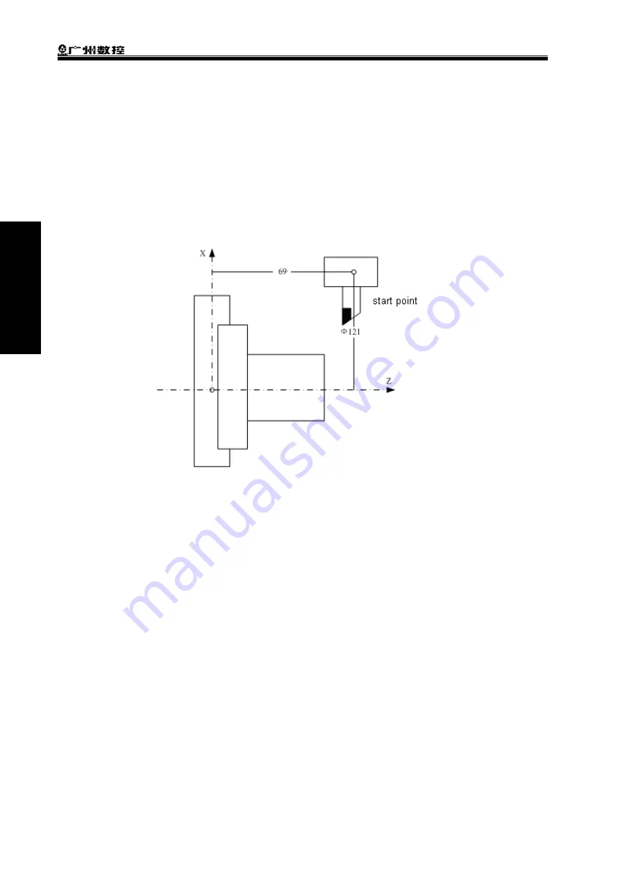
A workpiece coordinate system’s offset amount is determined by the diameter/radius assignation.
Example
)
it is expected that the reference point should be positioned from the workpiece’s origin
X=
Φ
120.0
(
diameter value
),
Z=70.0 to the current reference point X=
Φ
121.0
,
Z=69.0
,
the set offset
is shown below: X=1.0
,
Z=-1.0
2.8.2 Setting a Workpiece Coordinate System’s Offset Amount
Command function: the function can replace the direct input on the MDI panel to modify the
workpiece origin’s offset and the workpiece coordinate system’s offset value
in the coordinate setting page.
Command format
:
G10 L2 Pp IP_;
Command explanation:p = 0
:
specify the external workpiece origin’s offset amount
;
p = 1~6
:
specify the workpiece origin ‘s offset amount relative to the workpiece
coordinate system 1~6
;
IP_
:
setting of axis’ address and workpiece origin’s offset amount.
An absolute code is the offset amount of each axis’ workpiece origin. An incremental code is to
add its value to the previous set workpiece origin’s offset amount of each axis (its result is the
offset amount of workpiece origin).
Note: when G10 is executed, the corresponding workpiece coordinate system’s offset value is refreshed
real-time, and #1220~#1226 setting values corresponded to the workpiece coordinate system are
simultaneously modified.
Summary of Contents for GSK988TA
Page 6: ...GSK988TA GSK988TA1 GSK988TB Turning Center CNC System User Manual Programming Operation VI ...
Page 19: ...1 Ⅰ Programming PROGRAMMING ...
Page 227: ...209 Ⅱ Operation OPERATION ...
Page 369: ...Chater 10 Machining Example 351 Ⅱ Operation ...
Page 371: ...353 Appendix ...
Page 465: ...Appendix 1 Parameters 447 Appendix ...
Page 479: ...Appendix 3 Interface Explanation 461 Appendix ...
Page 527: ...Appendix 5 Installation Layout 509 Appendix ...


