Chapter 8 Graph Setting & Display
333
Ⅱ
Operation
8.3 Simultaneous Graph Display and Operation
All cutting process of the part can be real-time checked with the graph simulation.
(
1
)
Press
function key to enter the graph page set;
(
2
)
On the graph page set, press
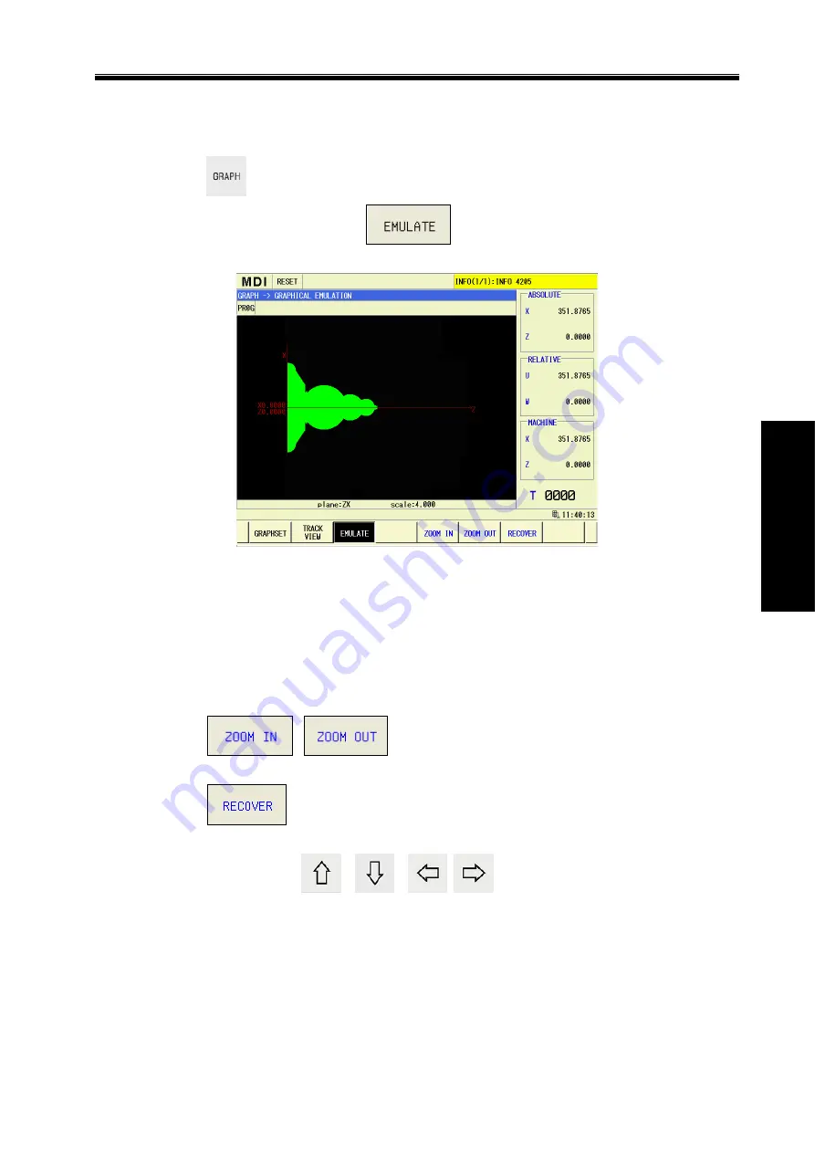
software key to enter the simulation graph
display page, which is shown as Fig. 8-3:
Fig.8-3
On the graph top, the running mode and status of the current system is displayed, the screen
right side is displayed the current absolute coordinate value, the relative coordinate value and the
current tool number, etc.
In the figure, the simulation graph information on XZ coordinate plane is displayed, the
coordinate plane on which the current simulation graph is and the magnification of the simulation
graph is displayed at the bottom of the graph simulation display screen.
During the graph simulation process, the simulation graph is operated as below:
(
1
)
Press
,
software key to scale up/down the simulation graph,
and the previous simulation graph is cleared;
(
2
)
Press
software key to restore the simulation graph into the original size and
the position, and the previous simulation graph is cleared;
(
3
)
Respectively press
,
,
,
key to move the simulation graph
upward/downward/leftward/rightward.
Note: The name of each axis is set by the parameter #1020, and each axis is set as the different names
with the letters, and then, on the path display page, the name of each coordinate plane and that of
the path coordinate can be switched correspondingly.
Summary of Contents for GSK988TA
Page 6: ...GSK988TA GSK988TA1 GSK988TB Turning Center CNC System User Manual Programming Operation VI ...
Page 19: ...1 Ⅰ Programming PROGRAMMING ...
Page 227: ...209 Ⅱ Operation OPERATION ...
Page 369: ...Chater 10 Machining Example 351 Ⅱ Operation ...
Page 371: ...353 Appendix ...
Page 465: ...Appendix 1 Parameters 447 Appendix ...
Page 479: ...Appendix 3 Interface Explanation 461 Appendix ...
Page 527: ...Appendix 5 Installation Layout 509 Appendix ...


