GSK988TA/GSK988TA1/GSK988TB Turning Center CNC System User Manual
【
Programming & Operation
】
268
Ⅱ
Operation
Setting method:
Function optional type: move the cursor to the required option, and then press
in the edit
keyboard.
Numerical value type: move the cursor the required option, press
to input a numerical
value, and then press
to complete the setting.
Press {return} or [cancel] on the edit keyboard to return the previous page.
Electronic gear ratio setting
Move the cursor to the electronic gear ratio setting, and press
to enter the electronic
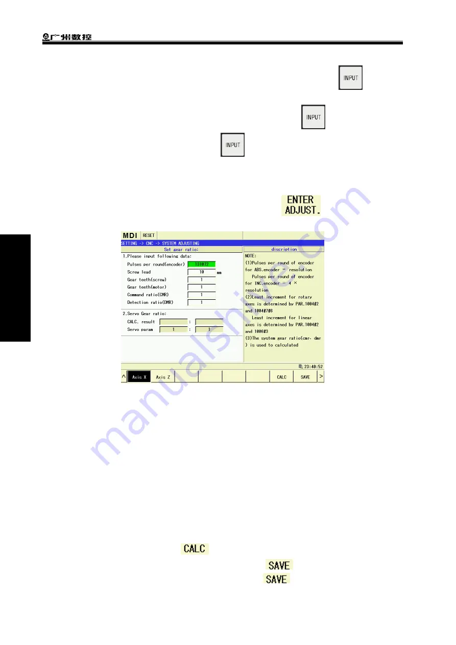
gear ratio setting page as Fig.3-48:
Fig.3-48
View and set the axis’ gear ratio in the page, and the set gear ratio is automatically saved to the
corresponding driver.
(
1
)
Select the required set axis as X axis in the above figure
;
(
2
)
Ensure the one-rotation pulse quantity of the encoder in data bar is correct (after the bus
connection is normally, one-rotation pulse quantity of the encoder can be read from the
driver);
(
3
)
Input the roll screw’s lead in the lead bar. Example: when the lead is 10mm, 10 is input as
the above figure;
(
4
)
When the lead screw: the motor is not 1:1, a gear quantity between the lead screw and
motor. When the ratio is 1:1, it is not input because the system defaults the ratio value;
(
5
)
The defaulted gear ratio is 1:1
,
and the ratio between the system checking multification ratio
and code multification ratio should be set if necessary;
(
6
)
After the above data is set.
is pressed
,
and the system automatically counts the
rear ratio and is displayed in the result. Then press
and the system automatically
save the result to the corresponding servo driver.
is not pressed when only the
Summary of Contents for GSK988TA
Page 6: ...GSK988TA GSK988TA1 GSK988TB Turning Center CNC System User Manual Programming Operation VI ...
Page 19: ...1 Ⅰ Programming PROGRAMMING ...
Page 227: ...209 Ⅱ Operation OPERATION ...
Page 369: ...Chater 10 Machining Example 351 Ⅱ Operation ...
Page 371: ...353 Appendix ...
Page 465: ...Appendix 1 Parameters 447 Appendix ...
Page 479: ...Appendix 3 Interface Explanation 461 Appendix ...
Page 527: ...Appendix 5 Installation Layout 509 Appendix ...


