GSK988TA/GSK988TA1/GSK988TB Turning Center CNC System User Manual
【
Programming & Operation
】
132
Ⅰ
Programming
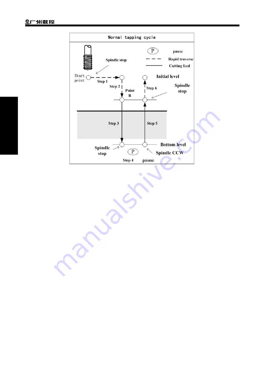
Fig. 2-77
Execution process:
①
The tool rapidly positions to the hole position from the start point (i.e., the point confirmed by
the hole position data in the initial plane);
②
Rapidly position to point R;
③
The spindle rotation M code outputting makes the spindle rotate (the spindle rotation before
the tapping cycle is executed, here M code does not output);
④
The tapping axis rotates along with the spindle rotation to cut to the hole bottom plane at the
speed specified by F; (when it is about to reach the programmed hole bottom’s coordinate
position, the spindle stops M05 output, it starts to decelerate to stop, and the tapping axis
remains feed till the spindle completely stops rotation);
⑤
Dwell is executed in the time specified by P;
⑥
The M code for spindle’s reverse rotation outputs (the spindle rotation direction is opposite to
the tool infeed);
⑦
The tapping axis executes the tool retraction to point R plane at the speed specified by F;
⑧
The spindle stops M05 output and stops rotation;
⑨
The tool rapidly return to the initial plane;
⑩
The common tapping cycle ends.
Note 1
:
The code is for the flexible tapping and the tapping axis’ feed follows the spindle rotation. After
the spindle stop signal M05 is valid at the hole bottom, the spindle decelerates to stop rotation, at
the moment, Z still feeds along with the spindle rotation till the spindle exactly stops, so, the
thread hole bottom position during the actual machining is higher or lower than the actual
programmed position, and the concrete error length is determined by the spindle speed and the
spindle brake equipment during tapping.
So, in order to safety, before executing G84/G88 tapping, the operator can move the slide to a
safety position. G84/G88 is executed without cutting a workpiece (note: here is not the dry run
Summary of Contents for GSK988TA
Page 6: ...GSK988TA GSK988TA1 GSK988TB Turning Center CNC System User Manual Programming Operation VI ...
Page 19: ...1 Ⅰ Programming PROGRAMMING ...
Page 227: ...209 Ⅱ Operation OPERATION ...
Page 369: ...Chater 10 Machining Example 351 Ⅱ Operation ...
Page 371: ...353 Appendix ...
Page 465: ...Appendix 1 Parameters 447 Appendix ...
Page 479: ...Appendix 3 Interface Explanation 461 Appendix ...
Page 527: ...Appendix 5 Installation Layout 509 Appendix ...


